CHAPTER – 03 BOOLEAN ALGEBRA Unit 1 Computer
Description: CHAPTER 03 BOOLEAN ALGEBRA Unit 1 Computer Systems and Organisation (CSO) XI Computer Science (083) Board : CBSE INTRODUCTION INTRODUCTION Developed by English Mathematician George Boole in between 1815 - 1864. It is described as an
Related Topics
Download Presentation
"CHAPTER – 03 BOOLEAN ALGEBRA Unit 1 Computer" is the property of its rightful owner. Permission is granted to download and print the materials on this website for personal, non-commercial use only, and to display it on your personal computer provided you do not modify the materials and that you retain all copyright notices contained in the materials. By downloading content from our website, you accept the terms of this agreement.
Presentation Transcript
slide1. CHAPTER – 03BOOLEAN ALGEBRA Unit 1 Computer Systems and Organisation (CSO) XI
Computer Science (083)
Board : CBSE<br>
slide2. INTRODUCTION<br>
slide3. INTRODUCTION Developed by English Mathematician George Boole in between 1815 - 1864.
It is described as an algebra of logic or an algebra of two values i.e True or False.
The term logic means a statement having binary decisions i.e True/Yes or False/No.<br>
slide4. APPLICATION OF BOOLEAN ALGEBRA<br>
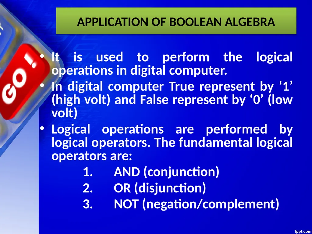
slide5. APPLICATION OF BOOLEAN ALGEBRA It is used to perform the logical operations in digital computer.
In digital computer True represent by ‘1’ (high volt) and False represent by ‘0’ (low volt)
Logical operations are performed by logical operators. The fundamental logical operators are:
1. AND (conjunction)
2. OR (disjunction)
3. NOT (negation/complement)<br>
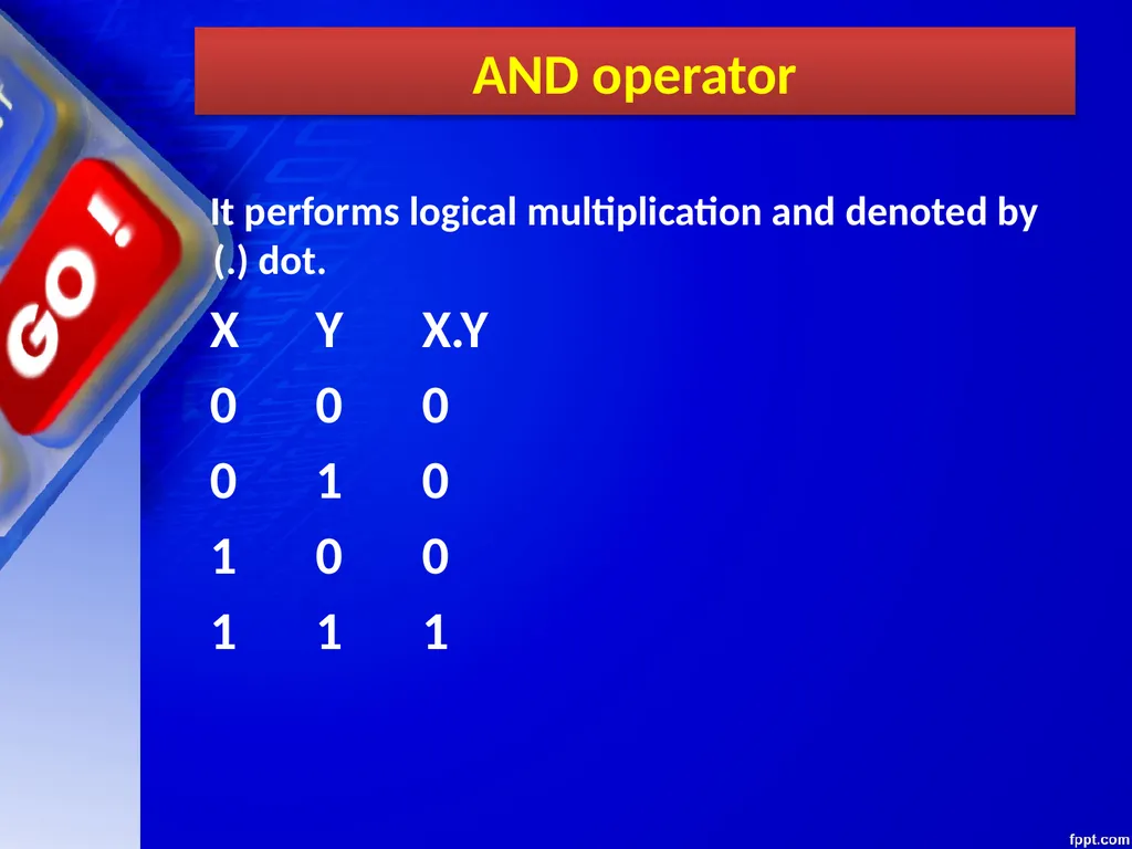
slide6. AND operator It performs logical multiplication and denoted by (.) dot.
X Y X.Y
0 0 0
0 1 0
1 0 0
1 1 1<br>
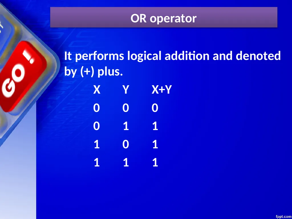
slide7. OR operator It performs logical addition and denoted by (+) plus.
X Y X+Y
0 0 0
0 1 1
1 0 1
1 1 1<br>
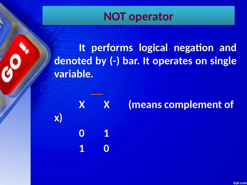
slide8. NOT operator It performs logical negation and denoted by (-) bar. It operates on single variable.
X X (means complement of x)
0 1
1 0<br>
slide9. Truth Table Truth table is a table that contains all possible values of logical variables/statements in a Boolean expression.
No. of possible combination =
2n, where n=number of variables used in a Boolean expression.<br>
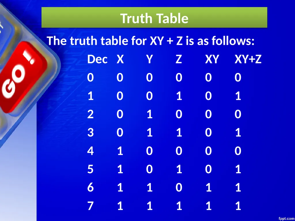
slide10. Truth Table The truth table for XY + Z is as follows:
Dec X Y Z XY XY+Z
0 0 0 0 0 0
1 0 0 1 0 1
2 0 1 0 0 0
3 0 1 1 0 1
4 1 0 0 0 0
5 1 0 1 0 1
6 1 1 0 1 1
7 1 1 1 1 1<br>
slide11. Tautology & Fallacy If the output of Boolean expression is always True or 1 is called Tautology.
If the output of Boolean expression is always False or 0 is called Fallacy.<br>
slide12. Tautology & Fallacy<br>
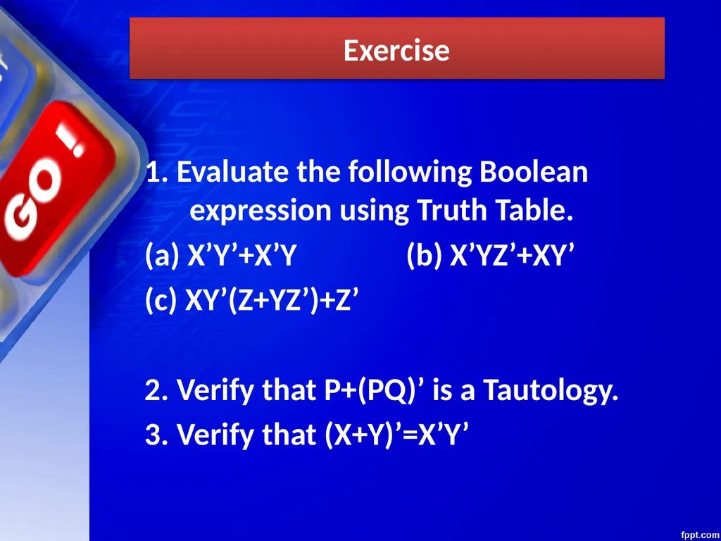
slide13. Exercise 1. Evaluate the following Boolean expression using Truth Table.
(a) X’Y’+X’Y (b) X’YZ’+XY’
(c) XY’(Z+YZ’)+Z’
2. Verify that P+(PQ)’ is a Tautology.
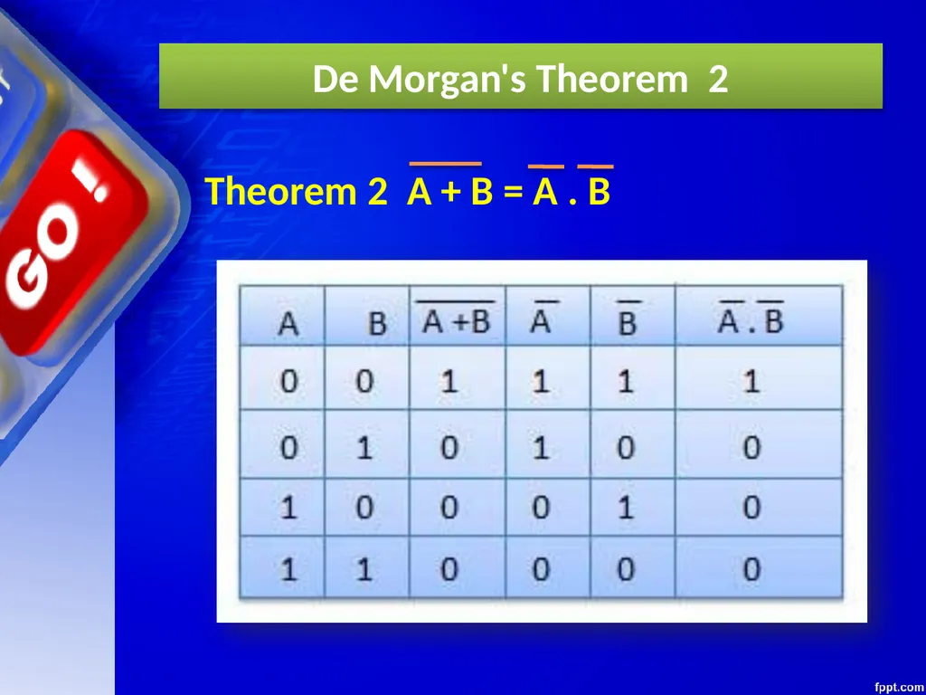
3. Verify that (X+Y)’=X’Y’<br>
slide14. Implementation Boolean Algebra applied in computers electronic circuits. These circuits perform Boolean operations and these are called logic circuits or logic gates.<br>
slide15. Logic Gate<br>
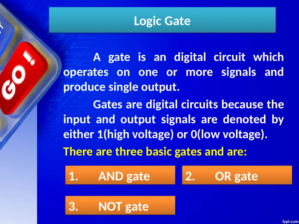
slide16. Logic Gate A gate is an digital circuit which operates on one or more signals and produce single output.
Gates are digital circuits because the input and output signals are denoted by either 1(high voltage) or 0(low voltage).
There are three basic gates and are: 1. AND gate 2. OR gate 3. NOT gate<br>
slide17. AND gate<br>
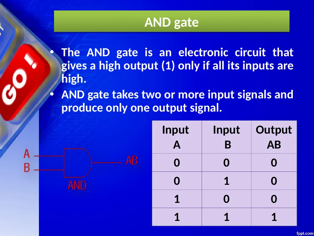
slide18. AND gate The AND gate is an electronic circuit that gives a high output (1) only if all its inputs are high.
AND gate takes two or more input signals and produce only one output signal.<br>
slide19. OR gate<br>
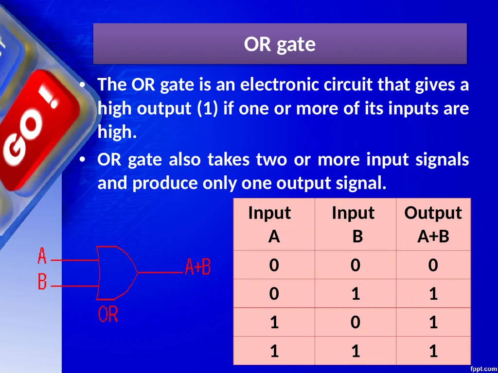
slide20. OR gate The OR gate is an electronic circuit that gives a high output (1) if one or more of its inputs are high.
OR gate also takes two or more input signals and produce only one output signal.<br>
slide21. NOT gate<br>
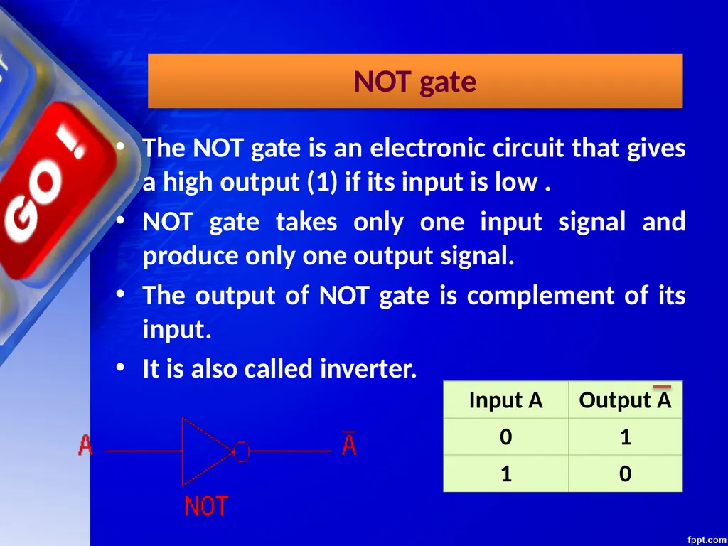
slide22. NOT gate The NOT gate is an electronic circuit that gives a high output (1) if its input is low .
NOT gate takes only one input signal and produce only one output signal.
The output of NOT gate is complement of its input.
It is also called inverter.<br>
slide23. PRACTICAL APPLICATIONS OF LOGIC GATES<br>
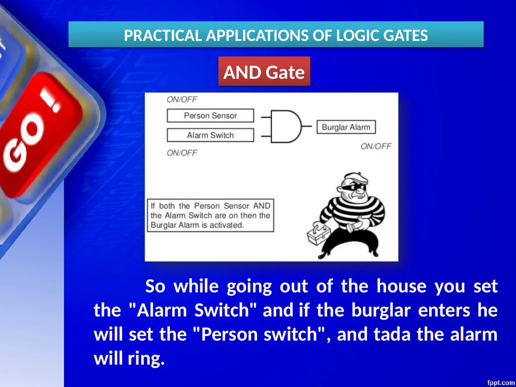
slide24. AND Gate So while going out of the house you set the "Alarm Switch" and if the burglar enters he will set the "Person switch", and tada the alarm will ring. PRACTICAL APPLICATIONS OF LOGIC GATES<br>
slide25. AND Gate PRACTICAL APPLICATIONS OF LOGIC GATES Electronic door will only open if it detects a person and the switch is set to unlocked.
Microwave will only start if the start button is pressed and the door close switch is closed.<br>
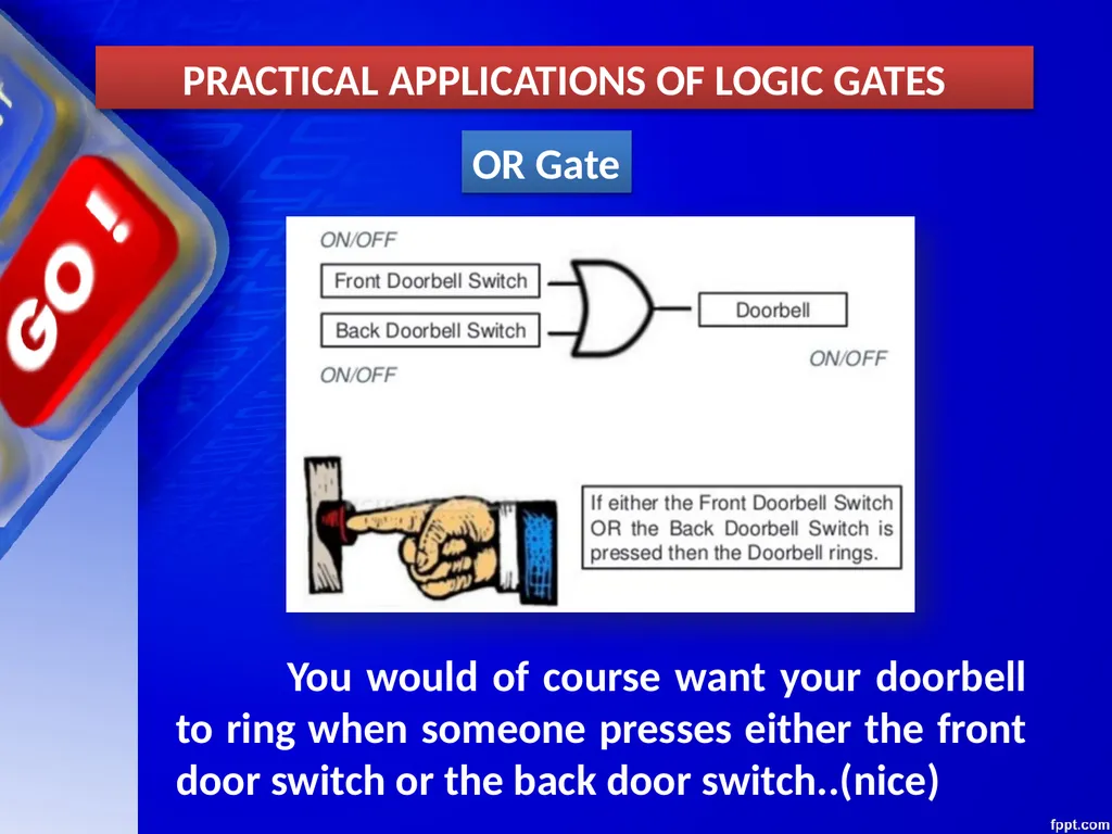
slide26. OR Gate You would of course want your doorbell to ring when someone presses either the front door switch or the back door switch..(nice) PRACTICAL APPLICATIONS OF LOGIC GATES<br>
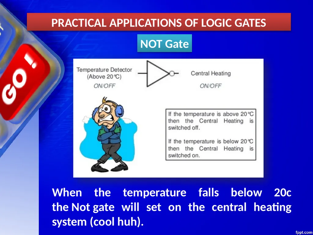
slide27. NOT Gate When the temperature falls below 20c the Not gate will set on the central heating system (cool huh). PRACTICAL APPLICATIONS OF LOGIC GATES<br>
slide28. NAND, NOR XOR, XNOR GATES<br>
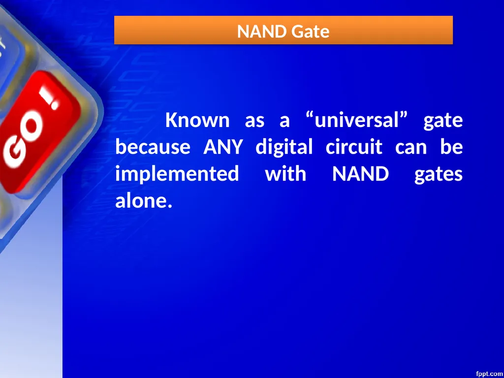
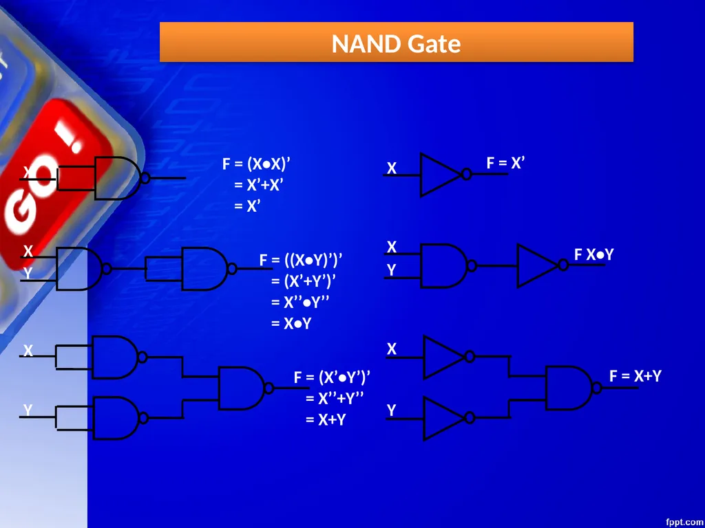
slide29. NAND Gate Known as a “universal” gate because ANY digital circuit can be implemented with NAND gates alone.<br>
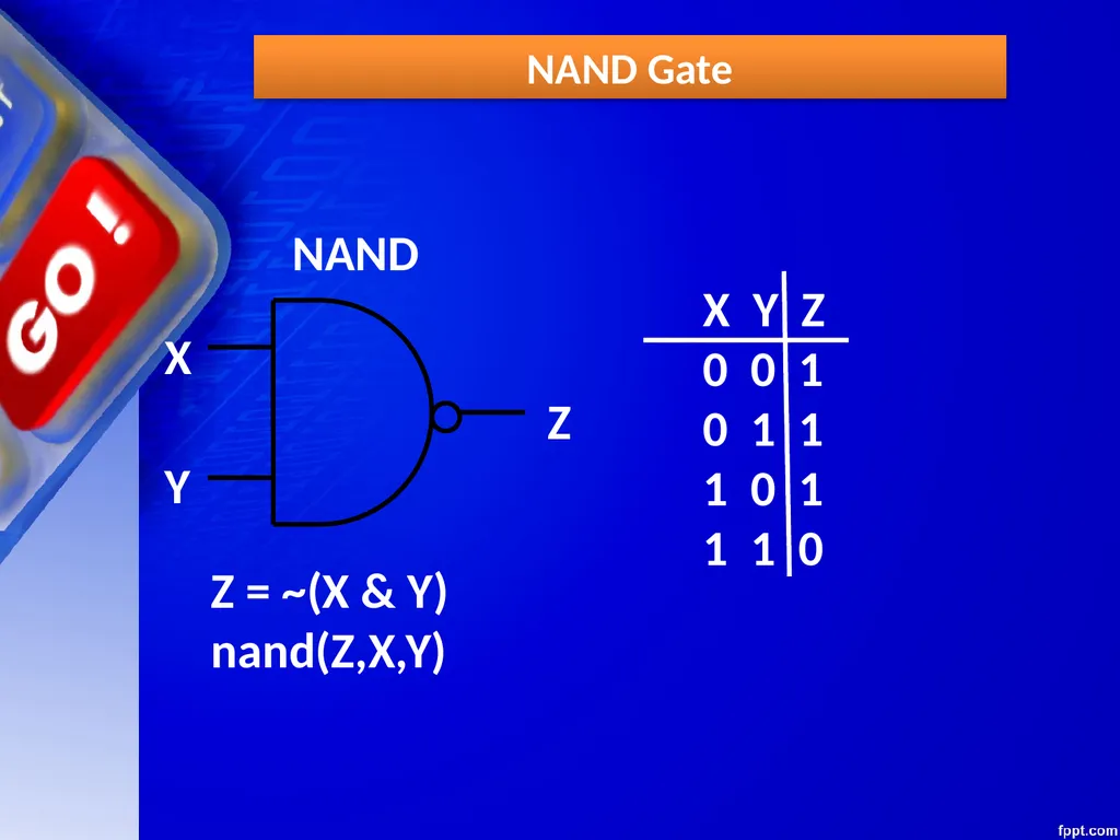
slide30. NAND Gate NAND X Y Z X Y Z
0 0 1
0 1 1
1 0 1
1 1 0 Z = ~(X & Y)
nand(Z,X,Y)<br>
slide31. NAND Gate<br>
slide32. NOR Gate<br>
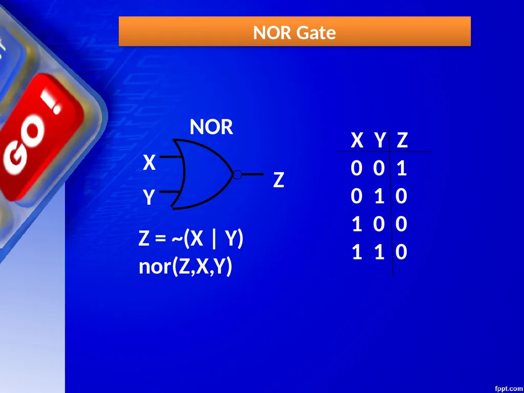
slide33. NOR Gate NOR X Y Z X Y Z
0 0 1
0 1 0
1 0 0
1 1 0 Z = ~(X | Y)
nor(Z,X,Y)<br>
slide34. Exclusive-OR Gate<br>
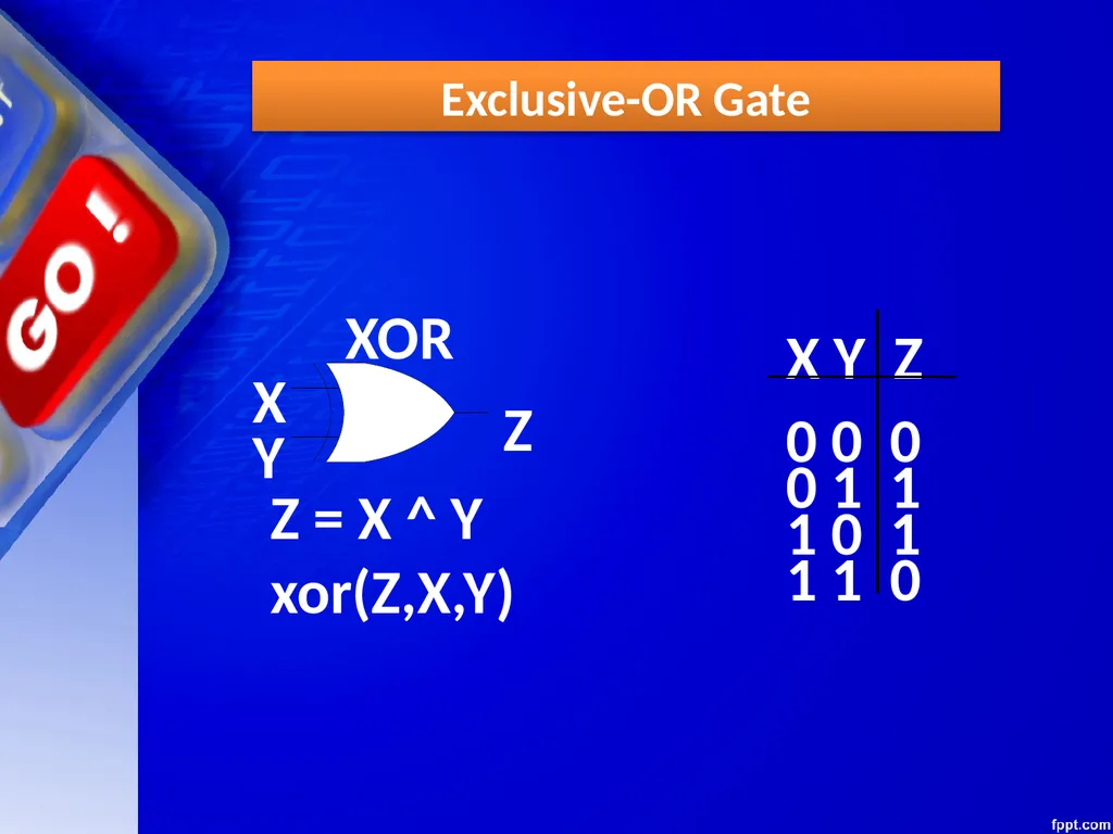
slide35. Exclusive-OR Gate X Y Z XOR X Y Z 0 0 0 0 1 1 1 0 1 1 1 0 Z = X ^ Y
xor(Z,X,Y)<br>
slide36. Exclusive-NOR Gate<br>
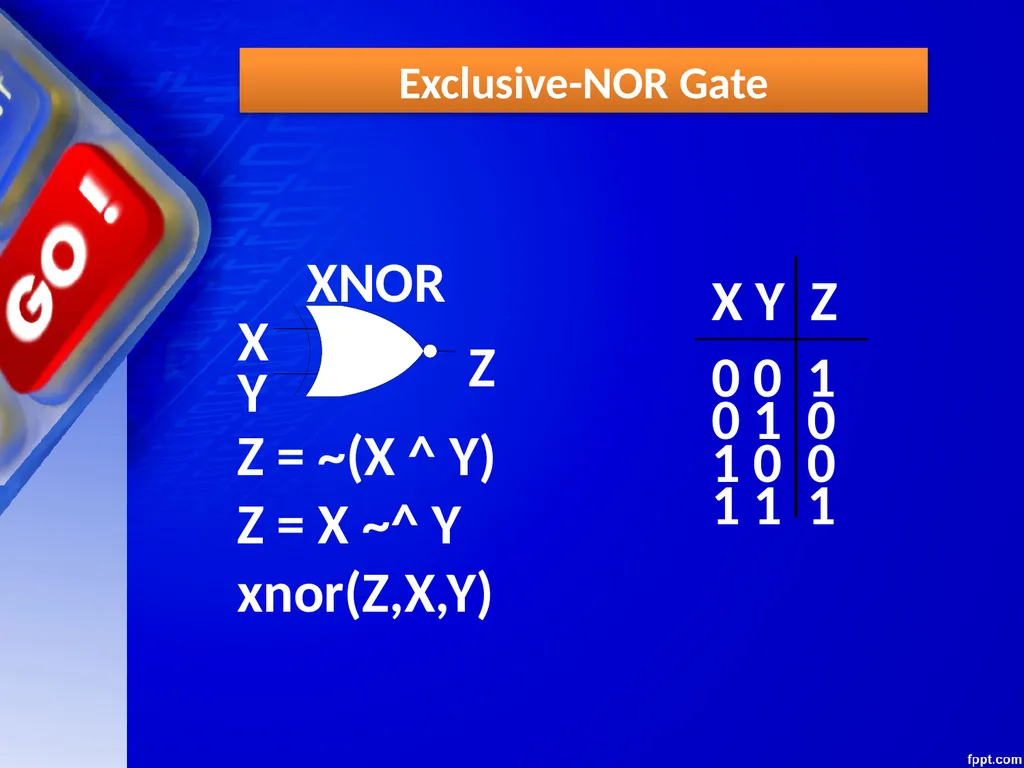
slide37. Exclusive-NOR Gate X Y Z XNOR X Y Z 0 0 1 0 1 0 1 0 0 1 1 1 Z = ~(X ^ Y)
Z = X ~^ Y
xnor(Z,X,Y)<br>
slide38. POWER CONSUMPTION OF SYSTEM<br>
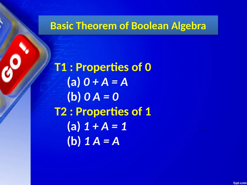
slide39. Basic Theorem of Boolean Algebra T1 : Properties of 0
(a) 0 + A = A (b) 0 A = 0
T2 : Properties of 1
(a) 1 + A = 1 (b) 1 A = A<br>
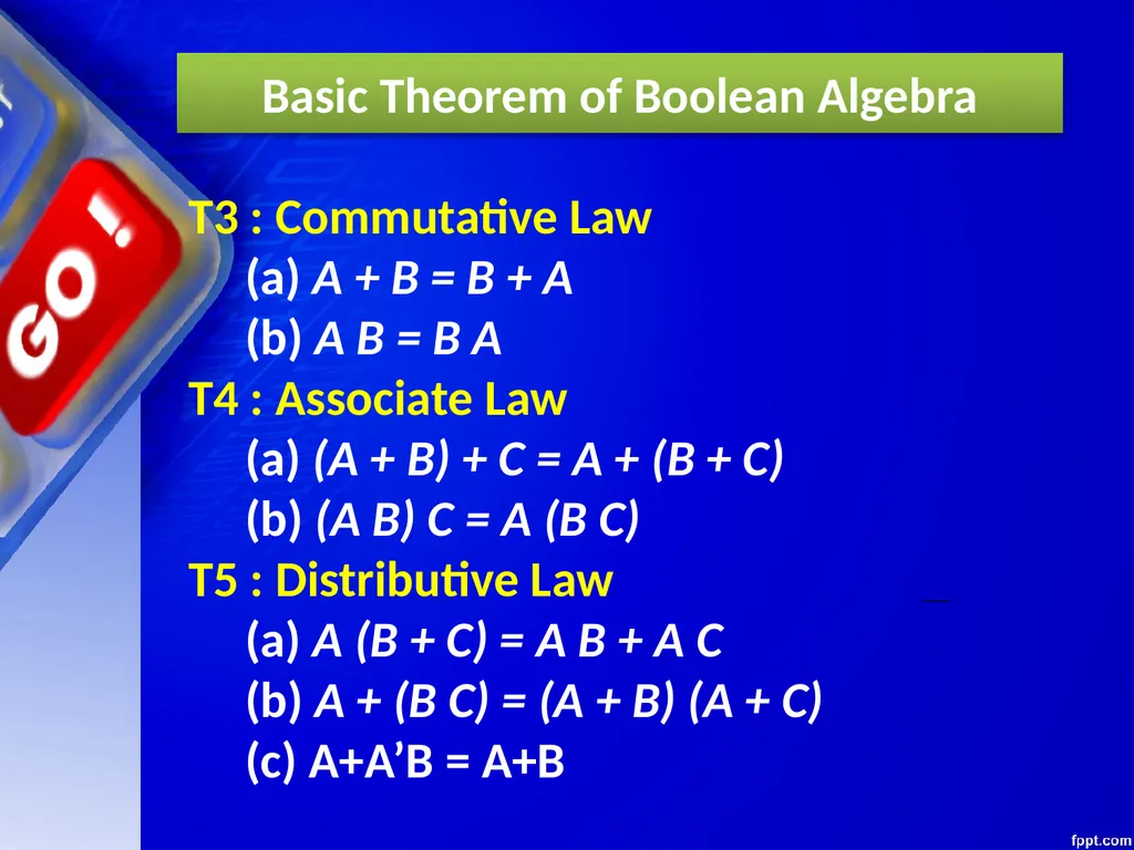
slide40. Basic Theorem of Boolean Algebra T3 : Commutative Law
(a) A + B = B + A(b) A B = B A
T4 : Associate Law
(a) (A + B) + C = A + (B + C) (b) (A B) C = A (B C)
T5 : Distributive Law
(a) A (B + C) = A B + A C(b) A + (B C) = (A + B) (A + C)
(c) A+A’B = A+B<br>
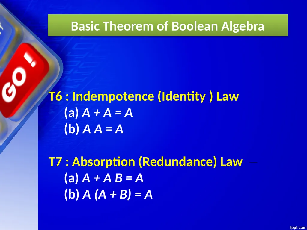
slide41. T6 : Indempotence (Identity ) Law
(a) A + A = A (b) A A = A
T7 : Absorption (Redundance) Law
(a) A + A B = A (b) A (A + B) = A Basic Theorem of Boolean Algebra<br>
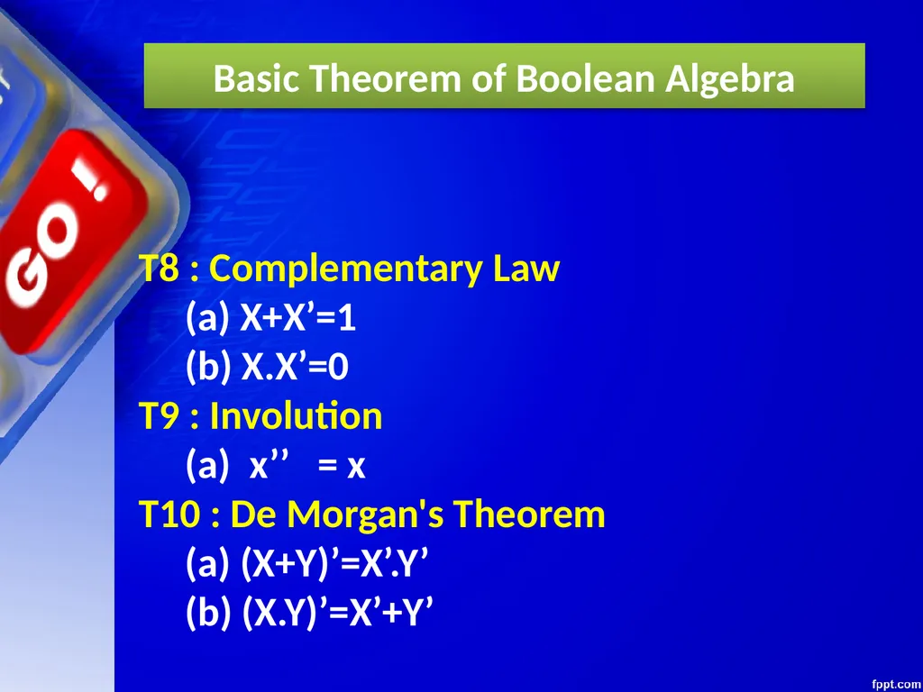
slide42. T8 : Complementary Law
(a) X+X’=1
(b) X.X’=0
T9 : Involution
(a) x’’ = x
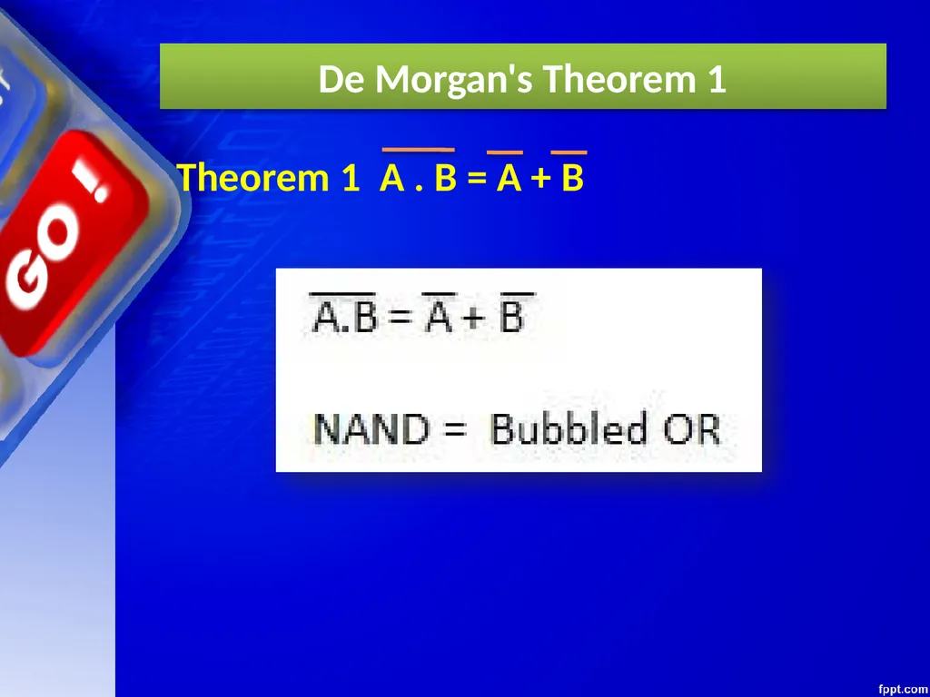
T10 : De Morgan's Theorem
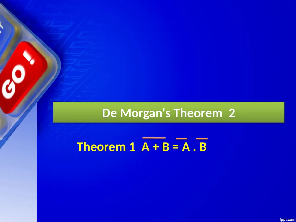
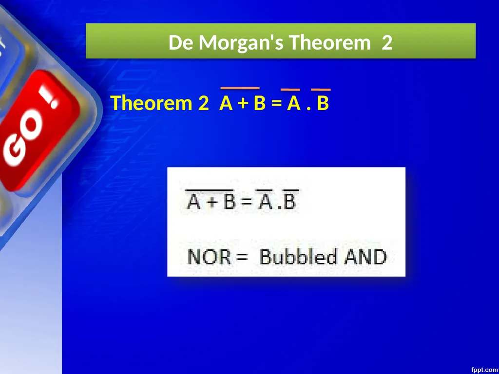
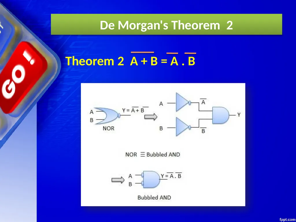
(a) (X+Y)’=X’.Y’
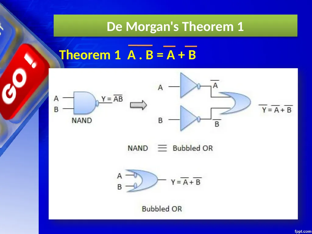
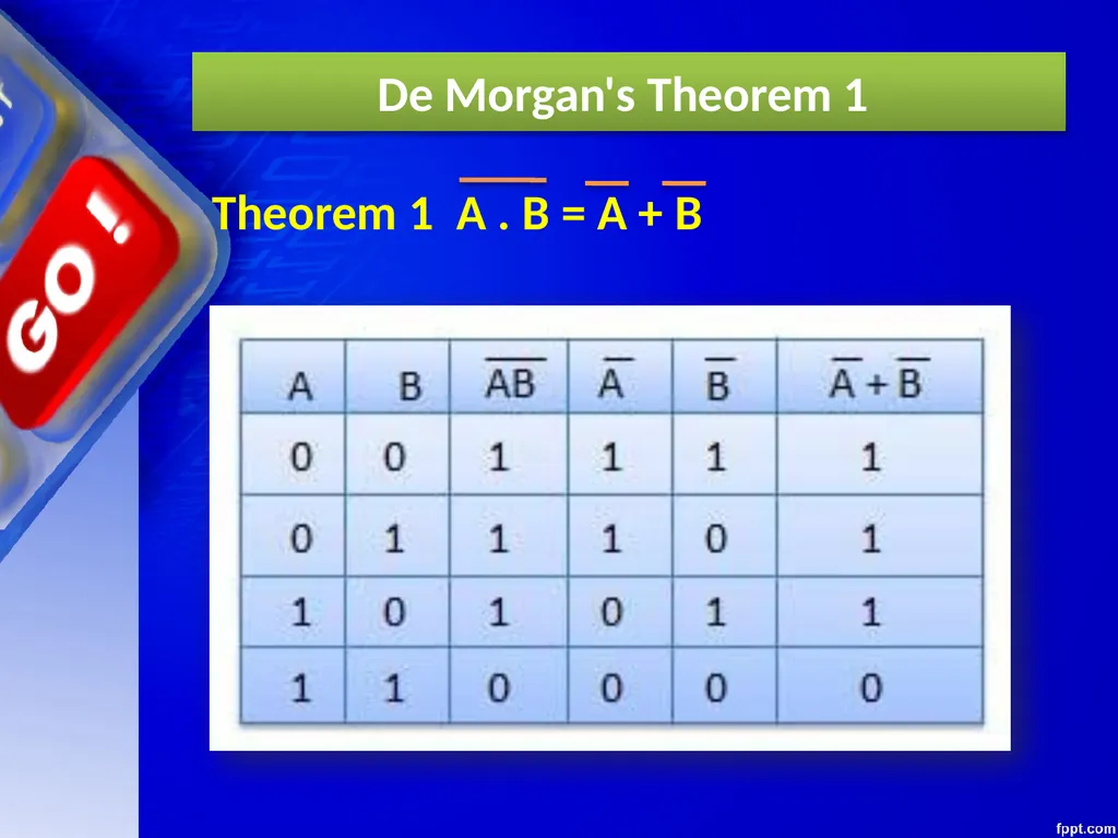
(b) (X.Y)’=X’+Y’ Basic Theorem of Boolean Algebra<br>
slide43. De Morgan's Theorem<br>
slide44. De Morgan's Theorem 1<br>
slide45. De Morgan's Theorem 1<br>
slide46. De Morgan's Theorem 1<br>
slide47. De Morgan's Theorem 2<br>

slide48. De Morgan's Theorem 2<br>
slide49. De Morgan's Theorem 2<br>
slide50. De Morgan's Theorem 2<br>
slide51. CLASS TEST<br>
slide52. Thank You<br>
Computer Science (083)
Board : CBSE<br>
slide2. INTRODUCTION<br>
slide3. INTRODUCTION Developed by English Mathematician George Boole in between 1815 - 1864.
It is described as an algebra of logic or an algebra of two values i.e True or False.
The term logic means a statement having binary decisions i.e True/Yes or False/No.<br>
slide4. APPLICATION OF BOOLEAN ALGEBRA<br>
slide5. APPLICATION OF BOOLEAN ALGEBRA It is used to perform the logical operations in digital computer.
In digital computer True represent by ‘1’ (high volt) and False represent by ‘0’ (low volt)
Logical operations are performed by logical operators. The fundamental logical operators are:
1. AND (conjunction)
2. OR (disjunction)
3. NOT (negation/complement)<br>
slide6. AND operator It performs logical multiplication and denoted by (.) dot.
X Y X.Y
0 0 0
0 1 0
1 0 0
1 1 1<br>
slide7. OR operator It performs logical addition and denoted by (+) plus.
X Y X+Y
0 0 0
0 1 1
1 0 1
1 1 1<br>
slide8. NOT operator It performs logical negation and denoted by (-) bar. It operates on single variable.
X X (means complement of x)
0 1
1 0<br>
slide9. Truth Table Truth table is a table that contains all possible values of logical variables/statements in a Boolean expression.
No. of possible combination =
2n, where n=number of variables used in a Boolean expression.<br>
slide10. Truth Table The truth table for XY + Z is as follows:
Dec X Y Z XY XY+Z
0 0 0 0 0 0
1 0 0 1 0 1
2 0 1 0 0 0
3 0 1 1 0 1
4 1 0 0 0 0
5 1 0 1 0 1
6 1 1 0 1 1
7 1 1 1 1 1<br>
slide11. Tautology & Fallacy If the output of Boolean expression is always True or 1 is called Tautology.
If the output of Boolean expression is always False or 0 is called Fallacy.<br>
slide12. Tautology & Fallacy<br>
slide13. Exercise 1. Evaluate the following Boolean expression using Truth Table.
(a) X’Y’+X’Y (b) X’YZ’+XY’
(c) XY’(Z+YZ’)+Z’
2. Verify that P+(PQ)’ is a Tautology.
3. Verify that (X+Y)’=X’Y’<br>
slide14. Implementation Boolean Algebra applied in computers electronic circuits. These circuits perform Boolean operations and these are called logic circuits or logic gates.<br>
slide15. Logic Gate<br>
slide16. Logic Gate A gate is an digital circuit which operates on one or more signals and produce single output.
Gates are digital circuits because the input and output signals are denoted by either 1(high voltage) or 0(low voltage).
There are three basic gates and are: 1. AND gate 2. OR gate 3. NOT gate<br>
slide17. AND gate<br>
slide18. AND gate The AND gate is an electronic circuit that gives a high output (1) only if all its inputs are high.
AND gate takes two or more input signals and produce only one output signal.<br>
slide19. OR gate<br>
slide20. OR gate The OR gate is an electronic circuit that gives a high output (1) if one or more of its inputs are high.
OR gate also takes two or more input signals and produce only one output signal.<br>
slide21. NOT gate<br>
slide22. NOT gate The NOT gate is an electronic circuit that gives a high output (1) if its input is low .
NOT gate takes only one input signal and produce only one output signal.
The output of NOT gate is complement of its input.
It is also called inverter.<br>
slide23. PRACTICAL APPLICATIONS OF LOGIC GATES<br>
slide24. AND Gate So while going out of the house you set the "Alarm Switch" and if the burglar enters he will set the "Person switch", and tada the alarm will ring. PRACTICAL APPLICATIONS OF LOGIC GATES<br>
slide25. AND Gate PRACTICAL APPLICATIONS OF LOGIC GATES Electronic door will only open if it detects a person and the switch is set to unlocked.
Microwave will only start if the start button is pressed and the door close switch is closed.<br>
slide26. OR Gate You would of course want your doorbell to ring when someone presses either the front door switch or the back door switch..(nice) PRACTICAL APPLICATIONS OF LOGIC GATES<br>
slide27. NOT Gate When the temperature falls below 20c the Not gate will set on the central heating system (cool huh). PRACTICAL APPLICATIONS OF LOGIC GATES<br>
slide28. NAND, NOR XOR, XNOR GATES<br>
slide29. NAND Gate Known as a “universal” gate because ANY digital circuit can be implemented with NAND gates alone.<br>
slide30. NAND Gate NAND X Y Z X Y Z
0 0 1
0 1 1
1 0 1
1 1 0 Z = ~(X & Y)
nand(Z,X,Y)<br>
slide31. NAND Gate<br>
slide32. NOR Gate<br>
slide33. NOR Gate NOR X Y Z X Y Z
0 0 1
0 1 0
1 0 0
1 1 0 Z = ~(X | Y)
nor(Z,X,Y)<br>
slide34. Exclusive-OR Gate<br>
slide35. Exclusive-OR Gate X Y Z XOR X Y Z 0 0 0 0 1 1 1 0 1 1 1 0 Z = X ^ Y
xor(Z,X,Y)<br>
slide36. Exclusive-NOR Gate<br>
slide37. Exclusive-NOR Gate X Y Z XNOR X Y Z 0 0 1 0 1 0 1 0 0 1 1 1 Z = ~(X ^ Y)
Z = X ~^ Y
xnor(Z,X,Y)<br>
slide38. POWER CONSUMPTION OF SYSTEM<br>
slide39. Basic Theorem of Boolean Algebra T1 : Properties of 0
(a) 0 + A = A (b) 0 A = 0
T2 : Properties of 1
(a) 1 + A = 1 (b) 1 A = A<br>
slide40. Basic Theorem of Boolean Algebra T3 : Commutative Law
(a) A + B = B + A(b) A B = B A
T4 : Associate Law
(a) (A + B) + C = A + (B + C) (b) (A B) C = A (B C)
T5 : Distributive Law
(a) A (B + C) = A B + A C(b) A + (B C) = (A + B) (A + C)
(c) A+A’B = A+B<br>
slide41. T6 : Indempotence (Identity ) Law
(a) A + A = A (b) A A = A
T7 : Absorption (Redundance) Law
(a) A + A B = A (b) A (A + B) = A Basic Theorem of Boolean Algebra<br>
slide42. T8 : Complementary Law
(a) X+X’=1
(b) X.X’=0
T9 : Involution
(a) x’’ = x
T10 : De Morgan's Theorem
(a) (X+Y)’=X’.Y’
(b) (X.Y)’=X’+Y’ Basic Theorem of Boolean Algebra<br>
slide43. De Morgan's Theorem<br>
slide44. De Morgan's Theorem 1<br>
slide45. De Morgan's Theorem 1<br>
slide46. De Morgan's Theorem 1<br>
slide47. De Morgan's Theorem 2<br>
slide48. De Morgan's Theorem 2<br>
slide49. De Morgan's Theorem 2<br>
slide50. De Morgan's Theorem 2<br>
slide51. CLASS TEST<br>

slide52. Thank You<br>