
CHAPTER 17 Temporary Pacing and Cardioversion



Description: CHAPTER 17 Temporary Pacing and Cardioversion Learning Objectives Familiarize oneself with the different modes of temporary cardiac pacing. Appreciate the range of complications that can occur due to the use of temporary pacemakers.
Related Topics
Download Presentation
"CHAPTER 17 Temporary Pacing and Cardioversion" is the property of its rightful owner. Permission is granted to download and print the materials on this website for personal, non-commercial use only, and to display it on your personal computer provided you do not modify the materials and that you retain all copyright notices contained in the materials. By downloading content from our website, you accept the terms of this agreement.
Presentation Transcript
slide1. CHAPTER 17 Temporary Pacing and Cardioversion<br>
slide2. Learning Objectives Familiarize oneself with the different modes of temporary cardiac pacing.
Appreciate the range of complications that can occur due to the use of temporary pacemakers.
Understand how electrodes are placed for each mode of temporary cardiac pacing.
Review the use of temporary pacemaker therapy for resynchronized cardioversion.
Summarize pre-, peri-, and postprocedural patient care with resynchronized cardioversion.<br>
slide3. Procedural Guidelines The procedures discussed in this presentation are an educational guide only.
Products’ instructions for use must be followed and adequate in-service education must be provided before a novice can perform a procedure.<br>
slide4. Temporary Pacemakers Produce and transmit an electrical impulse to the cardiac tissues.
Can sense the heart’s intrinsic electrical activity, when there is any.
Only placed in emergent situations or for high-risk procedures.<br>
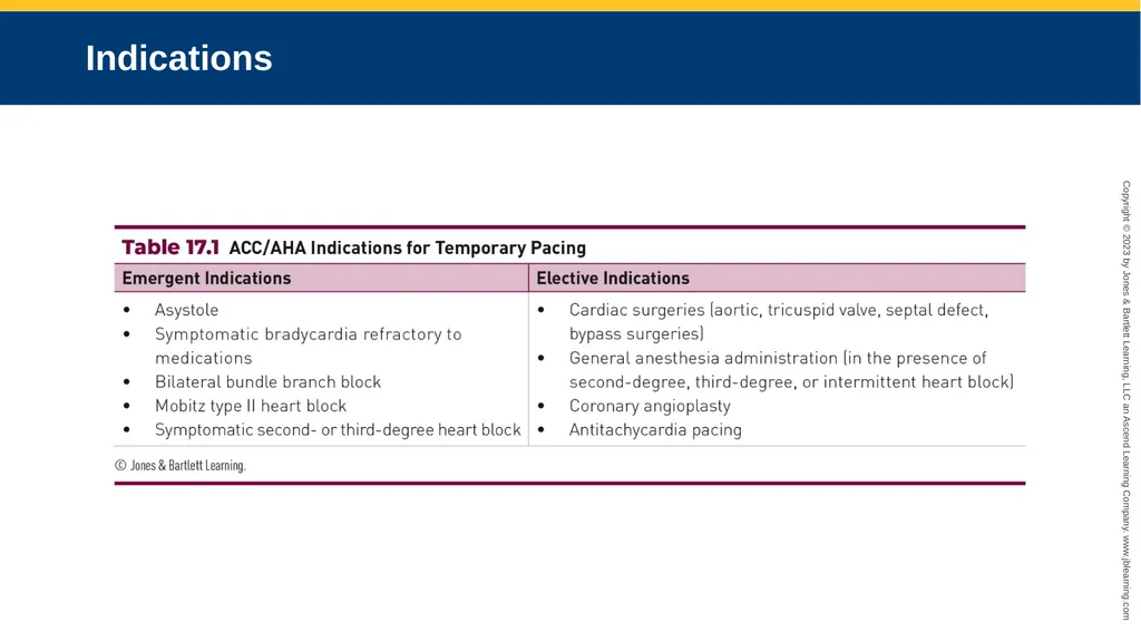
slide5. Indications<br>
slide6. Types of Temporary Pacemakers Five main methods for performing temporary cardiac pacing:
Transcutaneous
Transvenous
Transcoronary
Transesophageal
Transthoracic epicardial<br>
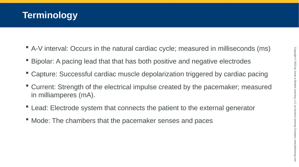
slide7. Terminology A-V interval: Occurs in the natural cardiac cycle; measured in milliseconds (ms)
Bipolar: A pacing lead that that has both positive and negative electrodes
Capture: Successful cardiac muscle depolarization triggered by cardiac pacing
Current: Strength of the electrical impulse created by the pacemaker; measured in milliamperes (mA).
Lead: Electrode system that connects the patient to the external generator
Mode: The chambers that the pacemaker senses and paces<br>
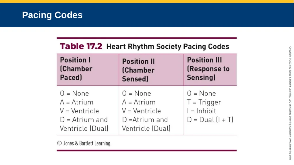
slide8. Pacing Codes<br>
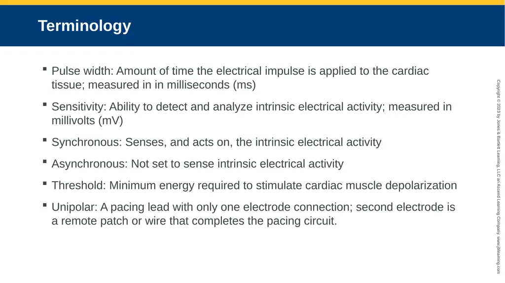
slide9. Terminology Pulse width: Amount of time the electrical impulse is applied to the cardiac tissue; measured in in milliseconds (ms)
Sensitivity: Ability to detect and analyze intrinsic electrical activity; measured in millivolts (mV)
Synchronous: Senses, and acts on, the intrinsic electrical activity
Asynchronous: Not set to sense intrinsic electrical activity
Threshold: Minimum energy required to stimulate cardiac muscle depolarization
Unipolar: A pacing lead with only one electrode connection; second electrode is a remote patch or wire that completes the pacing circuit.<br>
slide10. Transcutaneous Pacing (1 of 2) Delivers electrical impulse to the chest wall through pacing electrode patches.
Requires surface ECG to be sense contractions.
Uses two self-adhesive patches.
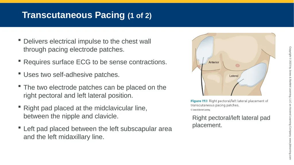
The two electrode patches can be placed on the right pectoral and left lateral position.
Right pad placed at the midclavicular line, between the nipple and clavicle.
Left pad placed between the left subscapular area and the left midaxillary line. Right pectoral/left lateral pad placement.<br>
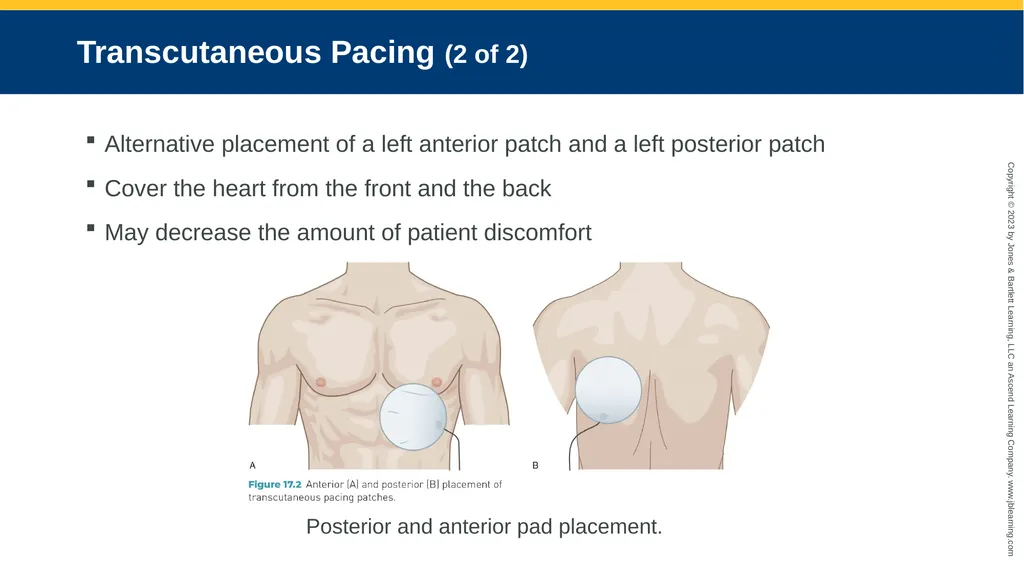
slide11. Transcutaneous Pacing (2 of 2) Alternative placement of a left anterior patch and a left posterior patch
Cover the heart from the front and the back
May decrease the amount of patient discomfort Posterior and anterior pad placement.<br>
slide12. Pulse Generator Settings The atria and ventricles are stimulated to contract at the same time.
The pulse width is generally not changed.
For pacing output use a current of 50–100 mA, depending on the patient.
Program to the lowest current level that successfully triggers cardiac depolarization.
Sensing is performed through the surface ECG electrodes connected to the pacing generator.
The pacing rate should be set to the point where the patient’s symptoms are alleviated, usually 80 bpm.<br>
slide13. Complications The normal atrial–ventricular conduction relationship is lost, reducing ventricular filling.
The electrical impulse triggers the chest’s skeletal muscles to contract, which is rather uncomfortable for the patient and often requires the patient to be sedated after 15–20 minutes of pacing.
There is an increased risk of failure to capture the cardiac muscle cells because the electrical impulse passes through the chest wall.<br>
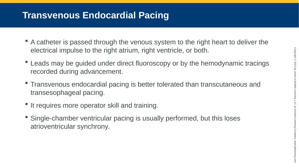
slide14. Transvenous Endocardial Pacing A catheter is passed through the venous system to the right heart to deliver the electrical impulse to the right atrium, right ventricle, or both.
Leads may be guided under direct fluoroscopy or by the hemodynamic tracings recorded during advancement.
Transvenous endocardial pacing is better tolerated than transcutaneous and transesophageal pacing.
It requires more operator skill and training.
Single-chamber ventricular pacing is usually performed, but this loses atrioventricular synchrony.<br>
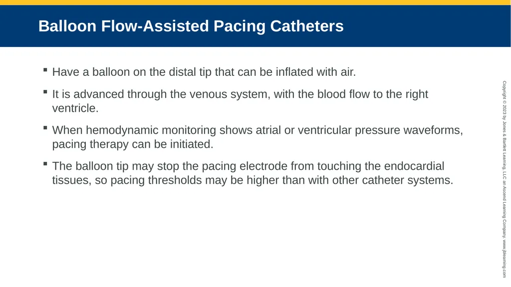
slide15. Balloon Flow-Assisted Pacing Catheters Have a balloon on the distal tip that can be inflated with air.
It is advanced through the venous system, with the blood flow to the right ventricle.
When hemodynamic monitoring shows atrial or ventricular pressure waveforms, pacing therapy can be initiated.
The balloon tip may stop the pacing electrode from touching the endocardial tissues, so pacing thresholds may be higher than with other catheter systems.<br>
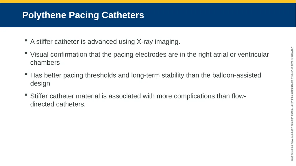
slide16. Polythene Pacing Catheters A stiffer catheter is advanced using X-ray imaging.
Visual confirmation that the pacing electrodes are in the right atrial or ventricular chambers
Has better pacing thresholds and long-term stability than the balloon-assisted design
Stiffer catheter material is associated with more complications than flow- directed catheters.<br>
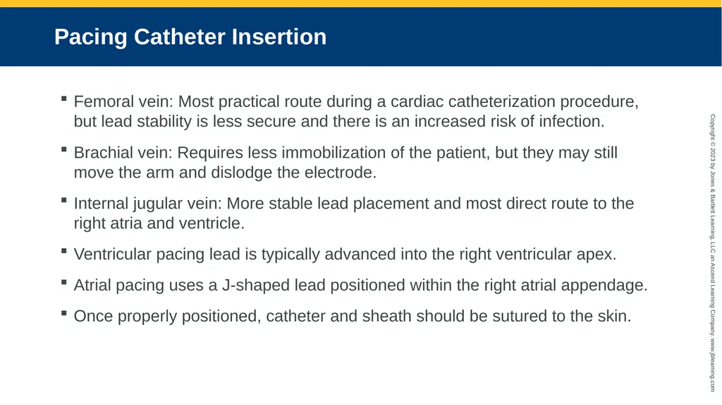
slide17. Pacing Catheter Insertion Femoral vein: Most practical route during a cardiac catheterization procedure, but lead stability is less secure and there is an increased risk of infection.
Brachial vein: Requires less immobilization of the patient, but they may still move the arm and dislodge the electrode.
Internal jugular vein: More stable lead placement and most direct route to the right atria and ventricle.
Ventricular pacing lead is typically advanced into the right ventricular apex.
Atrial pacing uses a J-shaped lead positioned within the right atrial appendage.
Once properly positioned, catheter and sheath should be sutured to the skin.<br>
slide18. Pulse Generator Settings Can be programmed for current, sensitivity, pulse width, and pacing rate.
First determine the chamber’s pacing threshold by pacing at a rate faster than the patient’s intrinsic rate (usually 80 bpm) with an output of 5.0 mA.
The current is then decreased until capture is lost, and then increased until it returns. This is the threshold.
Set the current at two to three times the threshold value.
Pulse width settings for the pacing of the right atrium and the right ventricle are typically 1.0 ms.
Single-chamber, ventricular pacing will require a higher pacing rate due to the loss of the A-V synchrony.<br>
slide19. Complications Lead dislodgment is often caused by patient movement.
Solid but comfortable immobilization of the limb can reduce the incidence.
Local and systemic infection may occur, especially with leads left in place for more than 48 hours.
Proper sterile technique must be observed during lead insertion.
Insertion site should be assessed regularly.<br>
slide20. Transcoronary Pacing Can be performed simply and quickly using a guiding catheter and a guidewire.
It should be considered for standby cardiac pacing during interventional procedures.
Hydrophilic wires do not conduct as well as conventional metal wires.
Pulse generator connection wires end in two alligator clips, one red and one black. The black clip is the negative (or cathode) end and the red clip is the positive (anode) end.
Requires a sterile suture needle and sterile needle holders.<br>
slide21. Electrode Placement Culprit artery accessed and a guidewire advanced distally in the vessel.
The suture needle should be inserted just distal to the sheath and the red alligator clip should be clamped onto it.
The black clip is clamped onto the guidewire where it leaves the sheath.
The other end of the pacing wires should then be attached to the pulse generator.<br>
slide22. Pulse Generator Settings The initial settings should be about 10 volts, with an impulse duration of 25 mA, at 60 or 70 pulses per minute.
Begin pacing at those settings, reducing them to establish thresholds.
It may be necessary to steer the wire into an intramyocardial branch to get capture at the lowest possible threshold.
Once the settings have been established, the interventional procedure can be completed.<br>
slide23. Complications Transcoronary pacing can induce coronary spasm, which can be relieved by an intracoronary bolus of nitrates or nifedipine.<br>
slide24. Transesophageal Pacing An electrode is inserted into the patient’s esophagus.
The electrical impulse is transmitted through the esophagus into the cardiac muscle.
It is typically used for patients suffering from atrial-focused bradycardias
This procedure is rarely performed in the ICVL.<br>
slide25. Electrode Placement Two methods of electrode placement:
A bipolar pacing catheter is inserted into the esophagus through the mouth or nasal passages into the esophagus by a physician.
A thin electrode wire attached to the small pacing electrode is covered by a disposable gelatin capsule that the patient swallows voluntarily.
Once in place, the electrode is held in position by taping the electrode wire to the patient’s cheek.<br>
slide26. Pulse Generator Settings Transesophageal pulse generators always function in an asynchronous mode.
They do not allow for inhibition of pacing if an intrinsic cardiac rhythm is present.
The pacing rate is set at a minimum of 12 bpm above the patient’s intrinsic heart rate.
A base rate of 80 bpm is adequate for most patients.<br>
slide27. Complications As the pacing electrode is advanced into the esophagus, many patients cough and gag. Using a spray anesthetic prior to insertion may decrease this reflex, but some patients still have significant coughing spells during catheter advancement.
Because emesis can occur during catheter advancement, there is a risk of aspirating stomach contents. Staff should be prepared to respond to a respiratory emergency if this would occur.
The formation of mucosal burns within the esophagus has been observed following transesophageal pacing, so it is not recommended for periods longer than 1 hour.<br>
slide28. Transthoracic Epicardial Pacing Not typically used to treat acute bradycardia arrhythmias
With surgical implantation, the leads are typically attached to the epicardial tissue of the right atria and right ventricle to allow for dual chamber pacing, if necessary.
Usually inserted during during cardiac surgical procedures to treat any postsurgical bradyarrhythmias that may develop
In the emergent situation, only one wire is advanced into the pericardial space, adjacent to the epicardium, generally placed for right ventricular pacing therapy
Skeletal muscle and diaphragm stimulation is uncommon with this system.<br>
slide29. Pulse Generator Settings Dependent on where the electrodes are placed on the heart
Can vary considerably between patients
The pacing rate should be set higher than 60 bpm and at a rate that is sufficient to alleviate symptoms.
Sequential atrial-ventricular depolarization requires lower-paced rates to achieve hemodynamic stability.
The typical setting for the epicardial paced rate is 70–90 bpm.<br>
slide30. Complications Most complications occur during the removal of the epicardial pacing leads.
The epicardial leads are lightly sutured onto the epicardium.
Removal requires the gentle traction on the external portion of the wire to pull them off the epicardium and out of the chest cavity.<br>
slide31. Synchronized Cardioversion Indicated for the treatment of supraventricular tachycardias in the stable patient after medications have failed
The pacing generator stimulates the heart faster than the patient’s intrinsic rate.
The pacemaker is then abruptly turned off.
Depolarization pauses as the action potentials are forced to reset.
This pause may allow the SA node time to regain control of cardiac depolarization.<br>
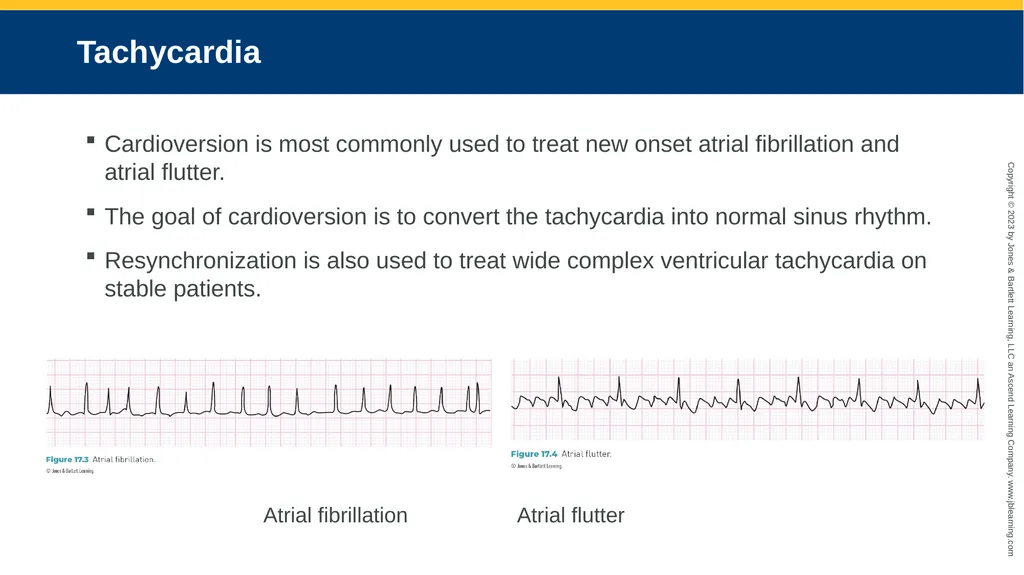
slide32. Tachycardia Cardioversion is most commonly used to treat new onset atrial fibrillation and atrial flutter.
The goal of cardioversion is to convert the tachycardia into normal sinus rhythm.
Resynchronization is also used to treat wide complex ventricular tachycardia on stable patients. Atrial fibrillation Atrial flutter<br>
slide33. Synchronized Cardioversion Preprocedure Care Provide patient and family education.
Perform an echocardiogram (usually transesophageal) to rule out thrombus in the heart chambers.
Ensure a stable and well-functioning intravenous (IV) line.
Provide oxygen.
Ensure that emergency equipment is readily available.<br>
slide34. During the Procedure Monitor vital signs:
ECG
Heart rate (from the defibrillator monitor)
Noninvasive blood pressure
Respiratory rate
Pulse oximetry.
Use pads instead of paddles whenever possible.<br>
slide35. Synchronization The synchronized function must be selected on the defibrillator.
The energy delivered during cardioversion must be synchronized with the QRS signal on the patient’s ECG.
Delivering the shock during the T wave portion of the cardiac cycle can put the patient into ventricular fibrillation.<br>
slide36. Medication Patient may be conscious or deeply sedated.
Conscious sedation: Versed (midazolam) and Sublimaze (fentanyl)
Romazicon (flumazenil) reverses Versed.
Narcan (naloxone) reverses fentanyl.
Antiarrhythmics (e.g., adenosine, amiodarone, cardizem, and metoprolol) given to:
Decrease heart rate.
Stabilize the patient.
Increase the chance that electrical cardioversion is successful.<br>
slide37. Synchronized Cardioversion Procedure Verify that the patient has reached the desired state of sedation.
Check heart rate, blood pressure, respiratory rate, and oxygen saturation.
Record the patient’s ECG before, during, and after the procedure.
Select the appropriate energy level, usually 50–200 J for biphasic defibrillators or 100–360 J for monophasic defibrillators.
Before pressing the charge button, ensure that no one is touching the patient.
Deliver the shock.
One shock is usually adequate to convert the patient to sinus rhythm.
May be repeated at a higher energy level, if needed.<br>
slide38. Postprocedure Care Check and document vital signs.
Ensure that the patient has fully recovered from sedation, checking for verbal responses to self, time, and place.
Patient instructions should include:
Any medication changes
Not driving for the following 24 hours
Having 2 days of rest before returning to work<br>
slide2. Learning Objectives Familiarize oneself with the different modes of temporary cardiac pacing.
Appreciate the range of complications that can occur due to the use of temporary pacemakers.
Understand how electrodes are placed for each mode of temporary cardiac pacing.
Review the use of temporary pacemaker therapy for resynchronized cardioversion.
Summarize pre-, peri-, and postprocedural patient care with resynchronized cardioversion.<br>
slide3. Procedural Guidelines The procedures discussed in this presentation are an educational guide only.
Products’ instructions for use must be followed and adequate in-service education must be provided before a novice can perform a procedure.<br>
slide4. Temporary Pacemakers Produce and transmit an electrical impulse to the cardiac tissues.
Can sense the heart’s intrinsic electrical activity, when there is any.
Only placed in emergent situations or for high-risk procedures.<br>
slide5. Indications<br>
slide6. Types of Temporary Pacemakers Five main methods for performing temporary cardiac pacing:
Transcutaneous
Transvenous
Transcoronary
Transesophageal
Transthoracic epicardial<br>
slide7. Terminology A-V interval: Occurs in the natural cardiac cycle; measured in milliseconds (ms)
Bipolar: A pacing lead that that has both positive and negative electrodes
Capture: Successful cardiac muscle depolarization triggered by cardiac pacing
Current: Strength of the electrical impulse created by the pacemaker; measured in milliamperes (mA).
Lead: Electrode system that connects the patient to the external generator
Mode: The chambers that the pacemaker senses and paces<br>
slide8. Pacing Codes<br>
slide9. Terminology Pulse width: Amount of time the electrical impulse is applied to the cardiac tissue; measured in in milliseconds (ms)
Sensitivity: Ability to detect and analyze intrinsic electrical activity; measured in millivolts (mV)
Synchronous: Senses, and acts on, the intrinsic electrical activity
Asynchronous: Not set to sense intrinsic electrical activity
Threshold: Minimum energy required to stimulate cardiac muscle depolarization
Unipolar: A pacing lead with only one electrode connection; second electrode is a remote patch or wire that completes the pacing circuit.<br>
slide10. Transcutaneous Pacing (1 of 2) Delivers electrical impulse to the chest wall through pacing electrode patches.
Requires surface ECG to be sense contractions.
Uses two self-adhesive patches.
The two electrode patches can be placed on the right pectoral and left lateral position.
Right pad placed at the midclavicular line, between the nipple and clavicle.
Left pad placed between the left subscapular area and the left midaxillary line. Right pectoral/left lateral pad placement.<br>
slide11. Transcutaneous Pacing (2 of 2) Alternative placement of a left anterior patch and a left posterior patch
Cover the heart from the front and the back
May decrease the amount of patient discomfort Posterior and anterior pad placement.<br>
slide12. Pulse Generator Settings The atria and ventricles are stimulated to contract at the same time.
The pulse width is generally not changed.
For pacing output use a current of 50–100 mA, depending on the patient.
Program to the lowest current level that successfully triggers cardiac depolarization.
Sensing is performed through the surface ECG electrodes connected to the pacing generator.
The pacing rate should be set to the point where the patient’s symptoms are alleviated, usually 80 bpm.<br>
slide13. Complications The normal atrial–ventricular conduction relationship is lost, reducing ventricular filling.
The electrical impulse triggers the chest’s skeletal muscles to contract, which is rather uncomfortable for the patient and often requires the patient to be sedated after 15–20 minutes of pacing.
There is an increased risk of failure to capture the cardiac muscle cells because the electrical impulse passes through the chest wall.<br>
slide14. Transvenous Endocardial Pacing A catheter is passed through the venous system to the right heart to deliver the electrical impulse to the right atrium, right ventricle, or both.
Leads may be guided under direct fluoroscopy or by the hemodynamic tracings recorded during advancement.
Transvenous endocardial pacing is better tolerated than transcutaneous and transesophageal pacing.
It requires more operator skill and training.
Single-chamber ventricular pacing is usually performed, but this loses atrioventricular synchrony.<br>
slide15. Balloon Flow-Assisted Pacing Catheters Have a balloon on the distal tip that can be inflated with air.
It is advanced through the venous system, with the blood flow to the right ventricle.
When hemodynamic monitoring shows atrial or ventricular pressure waveforms, pacing therapy can be initiated.
The balloon tip may stop the pacing electrode from touching the endocardial tissues, so pacing thresholds may be higher than with other catheter systems.<br>
slide16. Polythene Pacing Catheters A stiffer catheter is advanced using X-ray imaging.
Visual confirmation that the pacing electrodes are in the right atrial or ventricular chambers
Has better pacing thresholds and long-term stability than the balloon-assisted design
Stiffer catheter material is associated with more complications than flow- directed catheters.<br>
slide17. Pacing Catheter Insertion Femoral vein: Most practical route during a cardiac catheterization procedure, but lead stability is less secure and there is an increased risk of infection.
Brachial vein: Requires less immobilization of the patient, but they may still move the arm and dislodge the electrode.
Internal jugular vein: More stable lead placement and most direct route to the right atria and ventricle.
Ventricular pacing lead is typically advanced into the right ventricular apex.
Atrial pacing uses a J-shaped lead positioned within the right atrial appendage.
Once properly positioned, catheter and sheath should be sutured to the skin.<br>
slide18. Pulse Generator Settings Can be programmed for current, sensitivity, pulse width, and pacing rate.
First determine the chamber’s pacing threshold by pacing at a rate faster than the patient’s intrinsic rate (usually 80 bpm) with an output of 5.0 mA.
The current is then decreased until capture is lost, and then increased until it returns. This is the threshold.
Set the current at two to three times the threshold value.
Pulse width settings for the pacing of the right atrium and the right ventricle are typically 1.0 ms.
Single-chamber, ventricular pacing will require a higher pacing rate due to the loss of the A-V synchrony.<br>
slide19. Complications Lead dislodgment is often caused by patient movement.
Solid but comfortable immobilization of the limb can reduce the incidence.
Local and systemic infection may occur, especially with leads left in place for more than 48 hours.
Proper sterile technique must be observed during lead insertion.
Insertion site should be assessed regularly.<br>
slide20. Transcoronary Pacing Can be performed simply and quickly using a guiding catheter and a guidewire.
It should be considered for standby cardiac pacing during interventional procedures.
Hydrophilic wires do not conduct as well as conventional metal wires.
Pulse generator connection wires end in two alligator clips, one red and one black. The black clip is the negative (or cathode) end and the red clip is the positive (anode) end.
Requires a sterile suture needle and sterile needle holders.<br>
slide21. Electrode Placement Culprit artery accessed and a guidewire advanced distally in the vessel.
The suture needle should be inserted just distal to the sheath and the red alligator clip should be clamped onto it.
The black clip is clamped onto the guidewire where it leaves the sheath.
The other end of the pacing wires should then be attached to the pulse generator.<br>
slide22. Pulse Generator Settings The initial settings should be about 10 volts, with an impulse duration of 25 mA, at 60 or 70 pulses per minute.
Begin pacing at those settings, reducing them to establish thresholds.
It may be necessary to steer the wire into an intramyocardial branch to get capture at the lowest possible threshold.
Once the settings have been established, the interventional procedure can be completed.<br>
slide23. Complications Transcoronary pacing can induce coronary spasm, which can be relieved by an intracoronary bolus of nitrates or nifedipine.<br>
slide24. Transesophageal Pacing An electrode is inserted into the patient’s esophagus.
The electrical impulse is transmitted through the esophagus into the cardiac muscle.
It is typically used for patients suffering from atrial-focused bradycardias
This procedure is rarely performed in the ICVL.<br>
slide25. Electrode Placement Two methods of electrode placement:
A bipolar pacing catheter is inserted into the esophagus through the mouth or nasal passages into the esophagus by a physician.
A thin electrode wire attached to the small pacing electrode is covered by a disposable gelatin capsule that the patient swallows voluntarily.
Once in place, the electrode is held in position by taping the electrode wire to the patient’s cheek.<br>
slide26. Pulse Generator Settings Transesophageal pulse generators always function in an asynchronous mode.
They do not allow for inhibition of pacing if an intrinsic cardiac rhythm is present.
The pacing rate is set at a minimum of 12 bpm above the patient’s intrinsic heart rate.
A base rate of 80 bpm is adequate for most patients.<br>
slide27. Complications As the pacing electrode is advanced into the esophagus, many patients cough and gag. Using a spray anesthetic prior to insertion may decrease this reflex, but some patients still have significant coughing spells during catheter advancement.
Because emesis can occur during catheter advancement, there is a risk of aspirating stomach contents. Staff should be prepared to respond to a respiratory emergency if this would occur.
The formation of mucosal burns within the esophagus has been observed following transesophageal pacing, so it is not recommended for periods longer than 1 hour.<br>
slide28. Transthoracic Epicardial Pacing Not typically used to treat acute bradycardia arrhythmias
With surgical implantation, the leads are typically attached to the epicardial tissue of the right atria and right ventricle to allow for dual chamber pacing, if necessary.
Usually inserted during during cardiac surgical procedures to treat any postsurgical bradyarrhythmias that may develop
In the emergent situation, only one wire is advanced into the pericardial space, adjacent to the epicardium, generally placed for right ventricular pacing therapy
Skeletal muscle and diaphragm stimulation is uncommon with this system.<br>
slide29. Pulse Generator Settings Dependent on where the electrodes are placed on the heart
Can vary considerably between patients
The pacing rate should be set higher than 60 bpm and at a rate that is sufficient to alleviate symptoms.
Sequential atrial-ventricular depolarization requires lower-paced rates to achieve hemodynamic stability.
The typical setting for the epicardial paced rate is 70–90 bpm.<br>
slide30. Complications Most complications occur during the removal of the epicardial pacing leads.
The epicardial leads are lightly sutured onto the epicardium.
Removal requires the gentle traction on the external portion of the wire to pull them off the epicardium and out of the chest cavity.<br>
slide31. Synchronized Cardioversion Indicated for the treatment of supraventricular tachycardias in the stable patient after medications have failed
The pacing generator stimulates the heart faster than the patient’s intrinsic rate.
The pacemaker is then abruptly turned off.
Depolarization pauses as the action potentials are forced to reset.
This pause may allow the SA node time to regain control of cardiac depolarization.<br>
slide32. Tachycardia Cardioversion is most commonly used to treat new onset atrial fibrillation and atrial flutter.
The goal of cardioversion is to convert the tachycardia into normal sinus rhythm.
Resynchronization is also used to treat wide complex ventricular tachycardia on stable patients. Atrial fibrillation Atrial flutter<br>
slide33. Synchronized Cardioversion Preprocedure Care Provide patient and family education.
Perform an echocardiogram (usually transesophageal) to rule out thrombus in the heart chambers.
Ensure a stable and well-functioning intravenous (IV) line.
Provide oxygen.
Ensure that emergency equipment is readily available.<br>
slide34. During the Procedure Monitor vital signs:
ECG
Heart rate (from the defibrillator monitor)
Noninvasive blood pressure
Respiratory rate
Pulse oximetry.
Use pads instead of paddles whenever possible.<br>
slide35. Synchronization The synchronized function must be selected on the defibrillator.
The energy delivered during cardioversion must be synchronized with the QRS signal on the patient’s ECG.
Delivering the shock during the T wave portion of the cardiac cycle can put the patient into ventricular fibrillation.<br>
slide36. Medication Patient may be conscious or deeply sedated.
Conscious sedation: Versed (midazolam) and Sublimaze (fentanyl)
Romazicon (flumazenil) reverses Versed.
Narcan (naloxone) reverses fentanyl.
Antiarrhythmics (e.g., adenosine, amiodarone, cardizem, and metoprolol) given to:
Decrease heart rate.
Stabilize the patient.
Increase the chance that electrical cardioversion is successful.<br>
slide37. Synchronized Cardioversion Procedure Verify that the patient has reached the desired state of sedation.
Check heart rate, blood pressure, respiratory rate, and oxygen saturation.
Record the patient’s ECG before, during, and after the procedure.
Select the appropriate energy level, usually 50–200 J for biphasic defibrillators or 100–360 J for monophasic defibrillators.
Before pressing the charge button, ensure that no one is touching the patient.
Deliver the shock.
One shock is usually adequate to convert the patient to sinus rhythm.
May be repeated at a higher energy level, if needed.<br>
slide38. Postprocedure Care Check and document vital signs.
Ensure that the patient has fully recovered from sedation, checking for verbal responses to self, time, and place.
Patient instructions should include:
Any medication changes
Not driving for the following 24 hours
Having 2 days of rest before returning to work<br>