
CHAPTER 7 Operations Level Trench Rescue Shoring
Description: CHAPTER 7 Operations Level Trench Rescue Shoring Skill Drill 7-1: Installing Ground Pads 1. When a spoil pile interferes with the placement of lip protection, the best solution is to begin by removing the spoil while standing on a 2 foot
Related Topics
Download Presentation
"CHAPTER 7 Operations Level Trench Rescue Shoring" is the property of its rightful owner. Permission is granted to download and print the materials on this website for personal, non-commercial use only, and to display it on your personal computer provided you do not modify the materials and that you retain all copyright notices contained in the materials. By downloading content from our website, you accept the terms of this agreement.
Presentation Transcript
slide1. CHAPTER 7 Operations Level Trench Rescue Shoring<br>
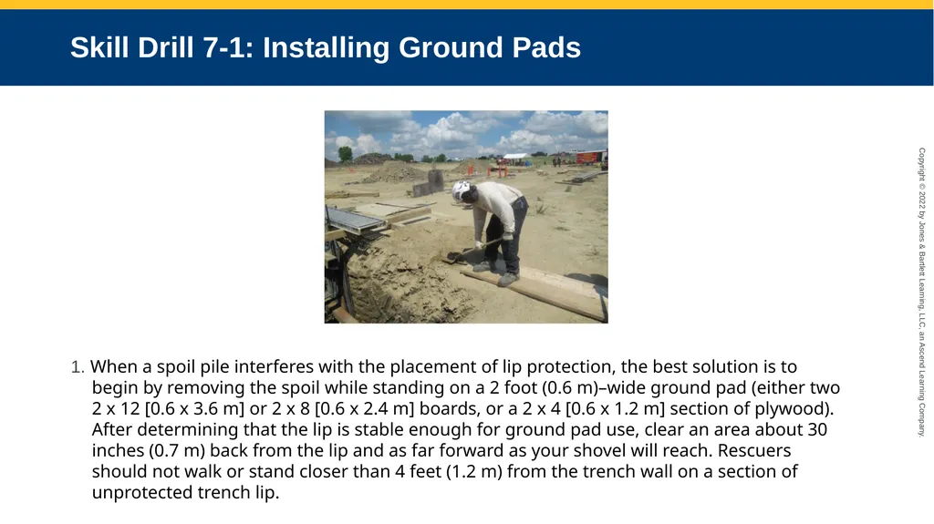
slide2. Skill Drill 7-1: Installing Ground Pads 1. When a spoil pile interferes with the placement of lip protection, the best solution is to begin by removing the spoil while standing on a 2 foot (0.6 m)–wide ground pad (either two 2 x 12 [0.6 x 3.6 m] or 2 x 8 [0.6 x 2.4 m] boards, or a 2 x 4 [0.6 x 1.2 m] section of plywood). After determining that the lip is stable enough for ground pad use, clear an area about 30 inches (0.7 m) back from the lip and as far forward as your shovel will reach. Rescuers should not walk or stand closer than 4 feet (1.2 m) from the trench wall on a section of unprotected trench lip.<br>
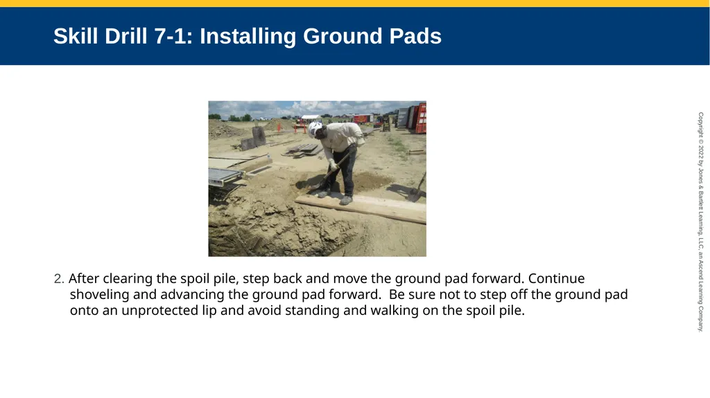
slide3. Skill Drill 7-1: Installing Ground Pads 2. After clearing the spoil pile, step back and move the ground pad forward. Continue shoveling and advancing the ground pad forward. Be sure not to step off the ground pad onto an unprotected lip and avoid standing and walking on the spoil pile.<br>
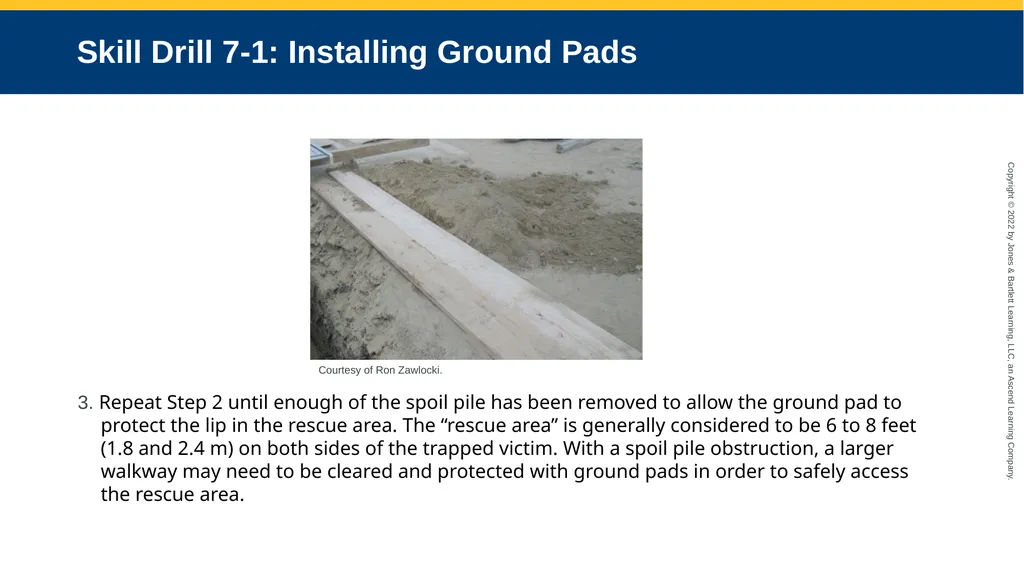
slide4. Skill Drill 7-1: Installing Ground Pads 3. Repeat Step 2 until enough of the spoil pile has been removed to allow the ground pad to protect the lip in the rescue area. The “rescue area” is generally considered to be 6 to 8 feet (1.8 and 2.4 m) on both sides of the trapped victim. With a spoil pile obstruction, a larger walkway may need to be cleared and protected with ground pads in order to safely access the rescue area. Courtesy of Ron Zawlocki.<br>
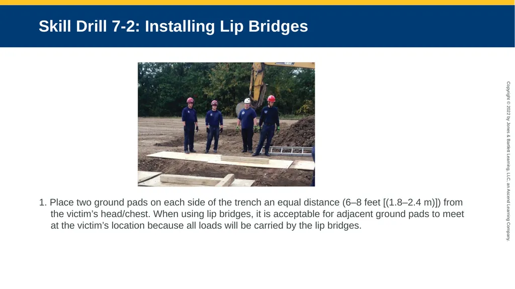
slide5. Skill Drill 7-2: Installing Lip Bridges 1. Place two ground pads on each side of the trench an equal distance (6–8 feet [(1.8–2.4 m)]) from the victim’s head/chest. When using lip bridges, it is acceptable for adjacent ground pads to meet at the victim’s location because all loads will be carried by the lip bridges.<br>
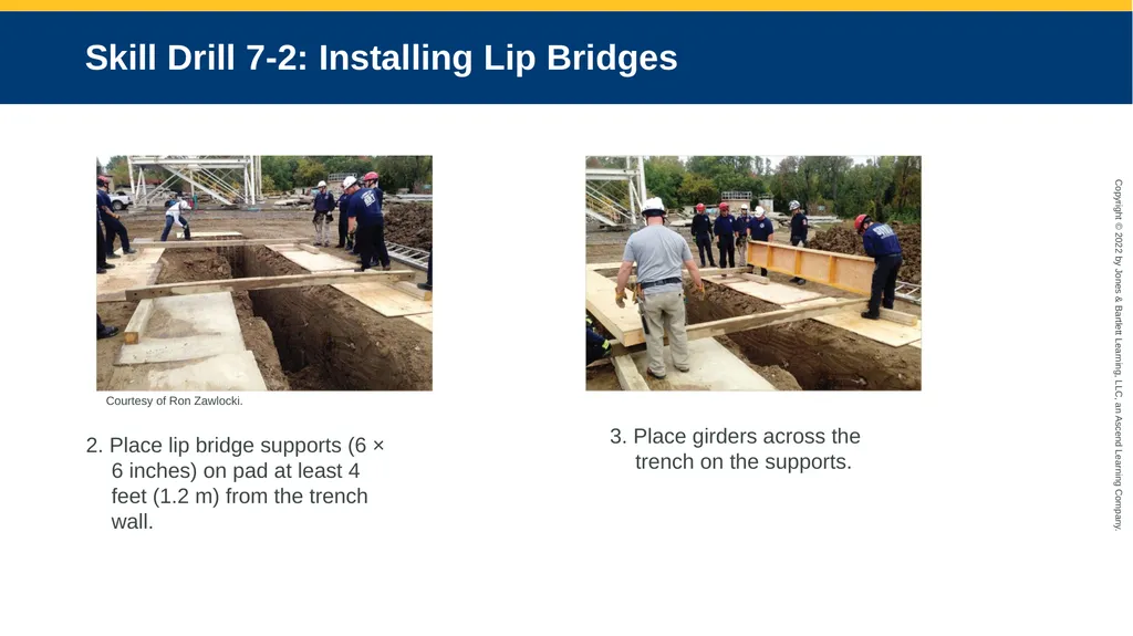
slide6. Skill Drill 7-2: Installing Lip Bridges 2. Place lip bridge supports (6 × 6 inches) on pad at least 4 feet (1.2 m) from the trench wall. 3. Place girders across the trench on the supports. Courtesy of Ron Zawlocki.<br>
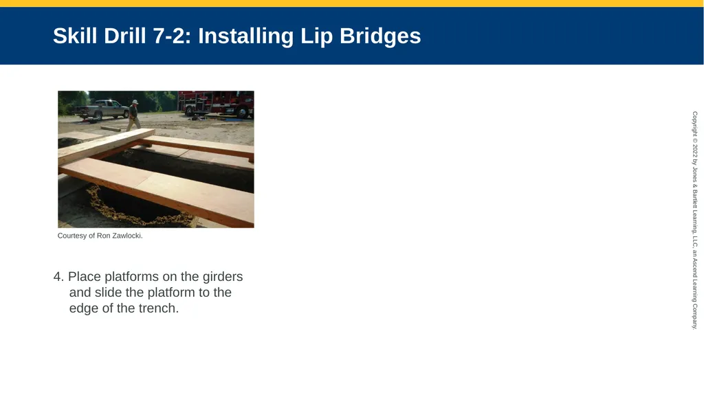
slide7. Skill Drill 7-2: Installing Lip Bridges 4. Place platforms on the girders and slide the platform to the edge of the trench. Courtesy of Ron Zawlocki.<br>
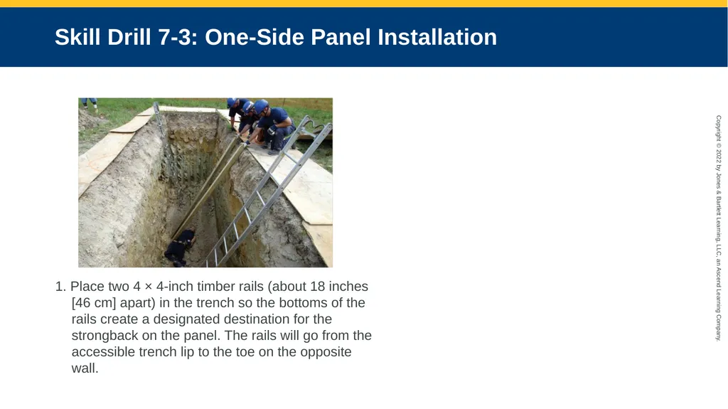
slide8. Skill Drill 7-3: One-Side Panel Installation 1. Place two 4 × 4-inch timber rails (about 18 inches [46 cm] apart) in the trench so the bottoms of the rails create a designated destination for the strongback on the panel. The rails will go from the accessible trench lip to the toe on the opposite wall.<br>
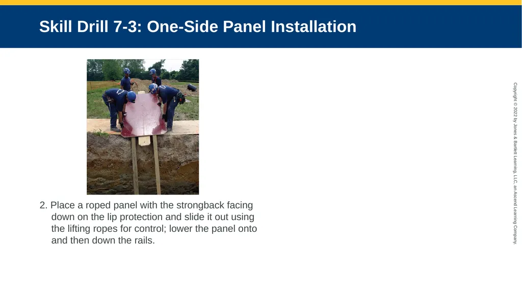
slide9. Skill Drill 7-3: One-Side Panel Installation 2. Place a roped panel with the strongback facing down on the lip protection and slide it out using the lifting ropes for control; lower the panel onto and then down the rails.<br>
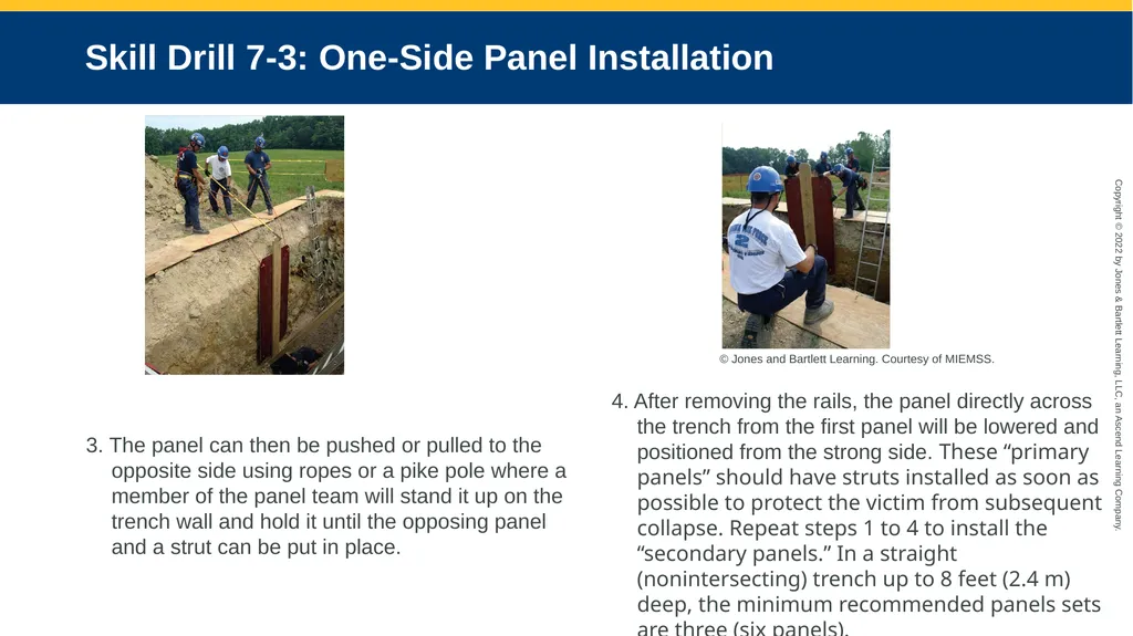
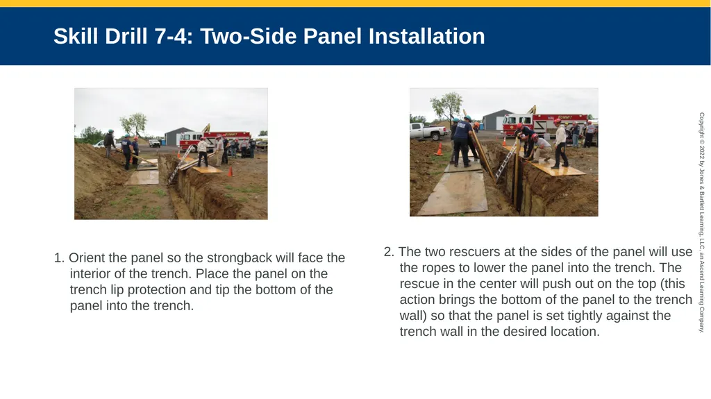
slide10. Skill Drill 7-3: One-Side Panel Installation 3. The panel can then be pushed or pulled to the opposite side using ropes or a pike pole where a member of the panel team will stand it up on the trench wall and hold it until the opposing panel and a strut can be put in place. 4. After removing the rails, the panel directly across the trench from the first panel will be lowered and positioned from the strong side. These “primary panels” should have struts installed as soon as possible to protect the victim from subsequent collapse. Repeat steps 1 to 4 to install the “secondary panels.” In a straight (nonintersecting) trench up to 8 feet (2.4 m) deep, the minimum recommended panels sets are three (six panels). © Jones and Bartlett Learning. Courtesy of MIEMSS.<br>
slide11. Skill Drill 7-4: Two-Side Panel Installation 1. Orient the panel so the strongback will face the interior of the trench. Place the panel on the trench lip protection and tip the bottom of the panel into the trench. 2. The two rescuers at the sides of the panel will use the ropes to lower the panel into the trench. The rescue in the center will push out on the top (this action brings the bottom of the panel to the trench wall) so that the panel is set tightly against the trench wall in the desired location.<br>
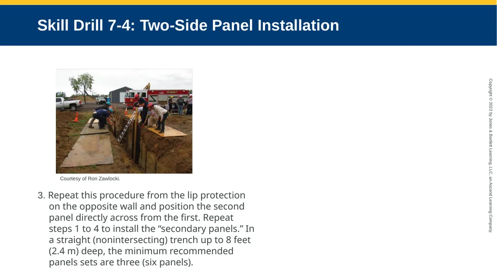
slide12. Skill Drill 7-4: Two-Side Panel Installation 3. Repeat this procedure from the lip protection on the opposite wall and position the second panel directly across from the first. Repeat steps 1 to 4 to install the “secondary panels.” In a straight (nonintersecting) trench up to 8 feet (2.4 m) deep, the minimum recommended panels sets are three (six panels). Courtesy of Ron Zawlocki.<br>
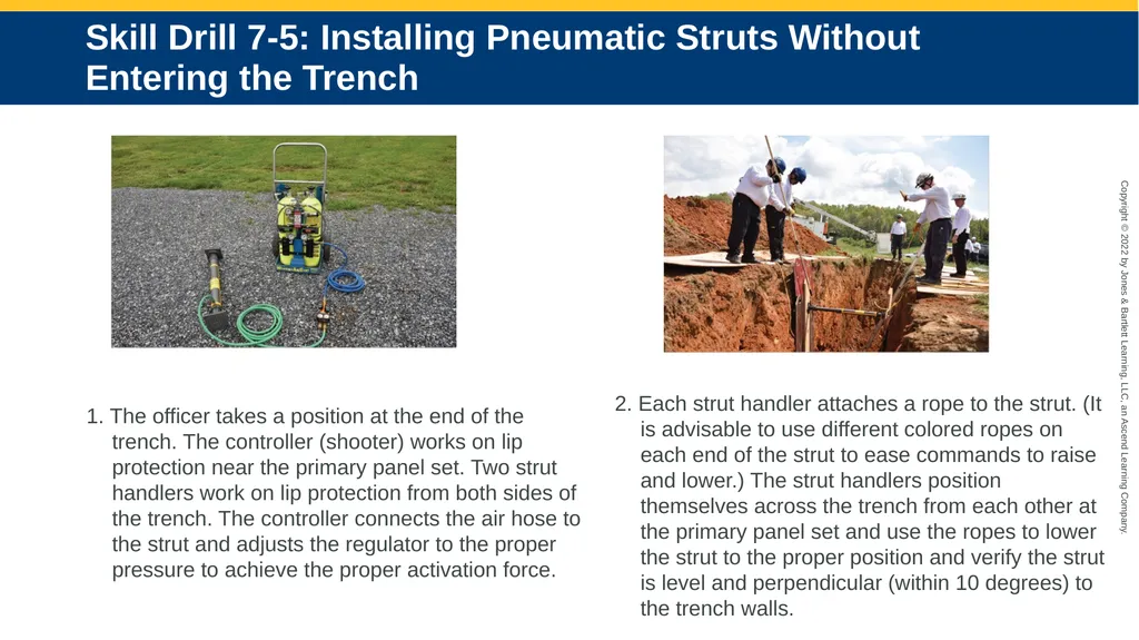
slide13. Skill Drill 7-5: Installing Pneumatic Struts Without Entering the Trench 1. The officer takes a position at the end of the trench. The controller (shooter) works on lip protection near the primary panel set. Two strut handlers work on lip protection from both sides of the trench. The controller connects the air hose to the strut and adjusts the regulator to the proper pressure to achieve the proper activation force. 2. Each strut handler attaches a rope to the strut. (It is advisable to use different colored ropes on each end of the strut to ease commands to raise and lower.) The strut handlers position themselves across the trench from each other at the primary panel set and use the ropes to lower the strut to the proper position and verify the strut is level and perpendicular (within 10 degrees) to the trench walls.<br>
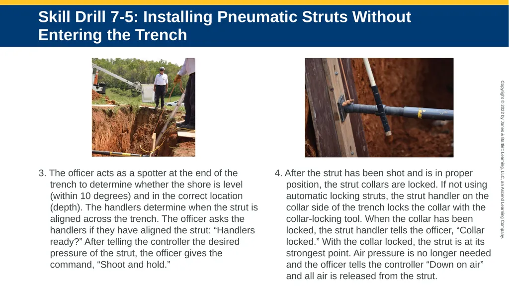
slide14. Skill Drill 7-5: Installing Pneumatic Struts Without Entering the Trench 3. The officer acts as a spotter at the end of the trench to determine whether the shore is level (within 10 degrees) and in the correct location (depth). The handlers determine when the strut is aligned across the trench. The officer asks the handlers if they have aligned the strut: “Handlers ready?” After telling the controller the desired pressure of the strut, the officer gives the command, “Shoot and hold.” 4. After the strut has been shot and is in proper position, the strut collars are locked. If not using automatic locking struts, the strut handler on the collar side of the trench locks the collar with the collar-locking tool. When the collar has been locked, the strut handler tells the officer, “Collar locked.” With the collar locked, the strut is at its strongest point. Air pressure is no longer needed and the officer tells the controller “Down on air” and all air is released from the strut.<br>
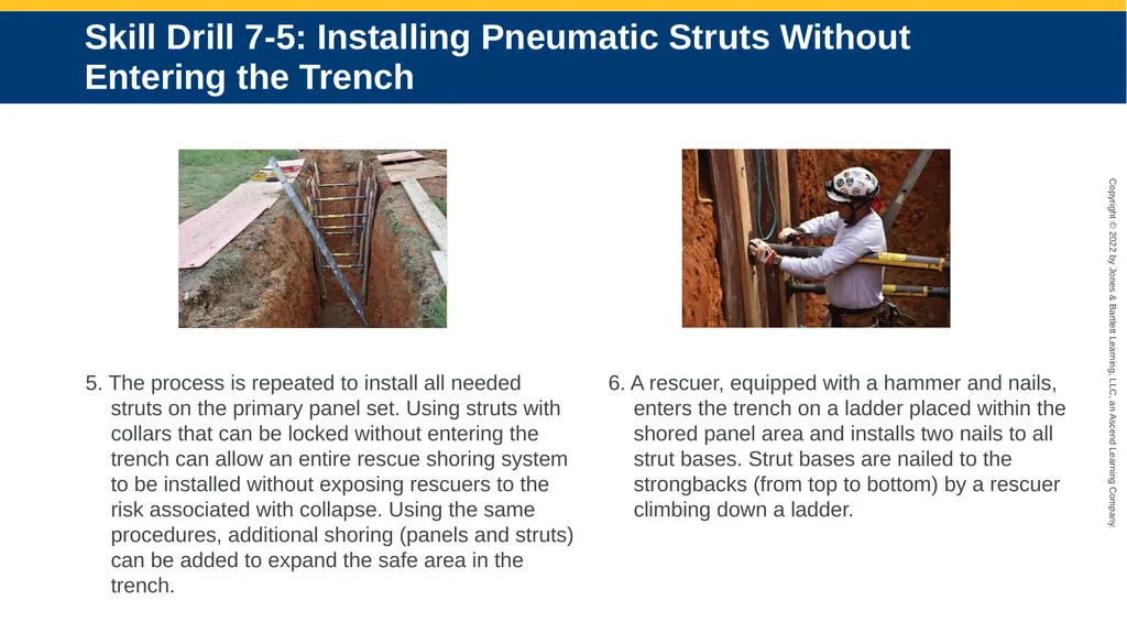
slide15. Skill Drill 7-5: Installing Pneumatic Struts Without Entering the Trench 5. The process is repeated to install all needed struts on the primary panel set. Using struts with collars that can be locked without entering the trench can allow an entire rescue shoring system to be installed without exposing rescuers to the risk associated with collapse. Using the same procedures, additional shoring (panels and struts) can be added to expand the safe area in the trench. 6. A rescuer, equipped with a hammer and nails, enters the trench on a ladder placed within the shored panel area and installs two nails to all strut bases. Strut bases are nailed to the strongbacks (from top to bottom) by a rescuer climbing down a ladder.<br>
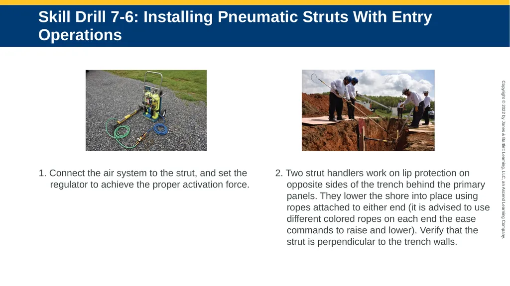
slide16. Skill Drill 7-6: Installing Pneumatic Struts With Entry Operations 1. Connect the air system to the strut, and set the regulator to achieve the proper activation force. 2. Two strut handlers work on lip protection on opposite sides of the trench behind the primary panels. They lower the shore into place using ropes attached to either end (it is advised to use different colored ropes on each end the ease commands to raise and lower). Verify that the strut is perpendicular to the trench walls.<br>
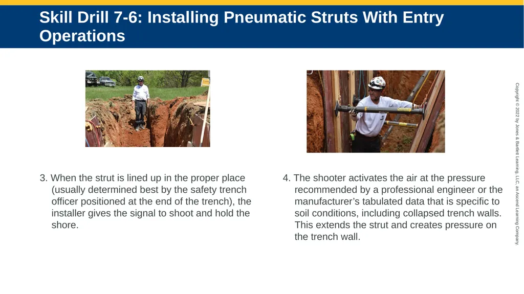
slide17. Skill Drill 7-6: Installing Pneumatic Struts With Entry Operations 3. When the strut is lined up in the proper place (usually determined best by the safety trench officer positioned at the end of the trench), the installer gives the signal to shoot and hold the shore. 4. The shooter activates the air at the pressure recommended by a professional engineer or the manufacturer’s tabulated data that is specific to soil conditions, including collapsed trench walls. This extends the strut and creates pressure on the trench wall.<br>
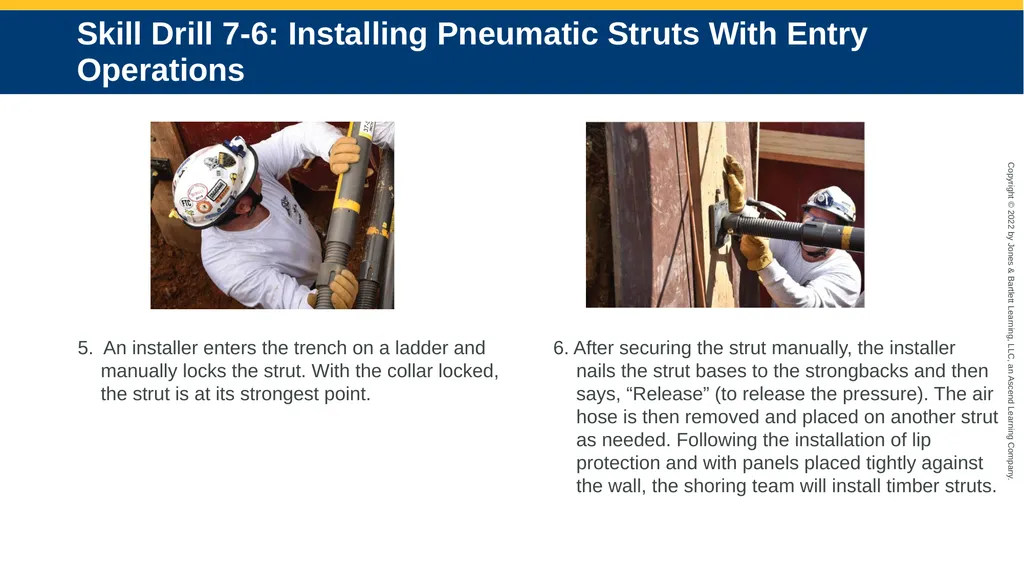
slide18. Skill Drill 7-6: Installing Pneumatic Struts With Entry Operations 5. An installer enters the trench on a ladder and manually locks the strut. With the collar locked, the strut is at its strongest point. 6. After securing the strut manually, the installer nails the strut bases to the strongbacks and then says, “Release” (to release the pressure). The air hose is then removed and placed on another strut as needed. Following the installation of lip protection and with panels placed tightly against the wall, the shoring team will install timber struts.<br>
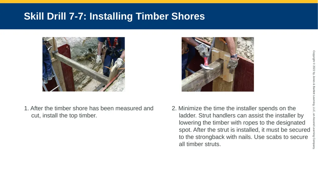
slide19. Skill Drill 7-7: Installing Timber Shores 1. After the timber shore has been measured and cut, install the top timber. 2. Minimize the time the installer spends on the ladder. Strut handlers can assist the installer by lowering the timber with ropes to the designated spot. After the strut is installed, it must be secured to the strongback with nails. Use scabs to secure all timber struts.<br>
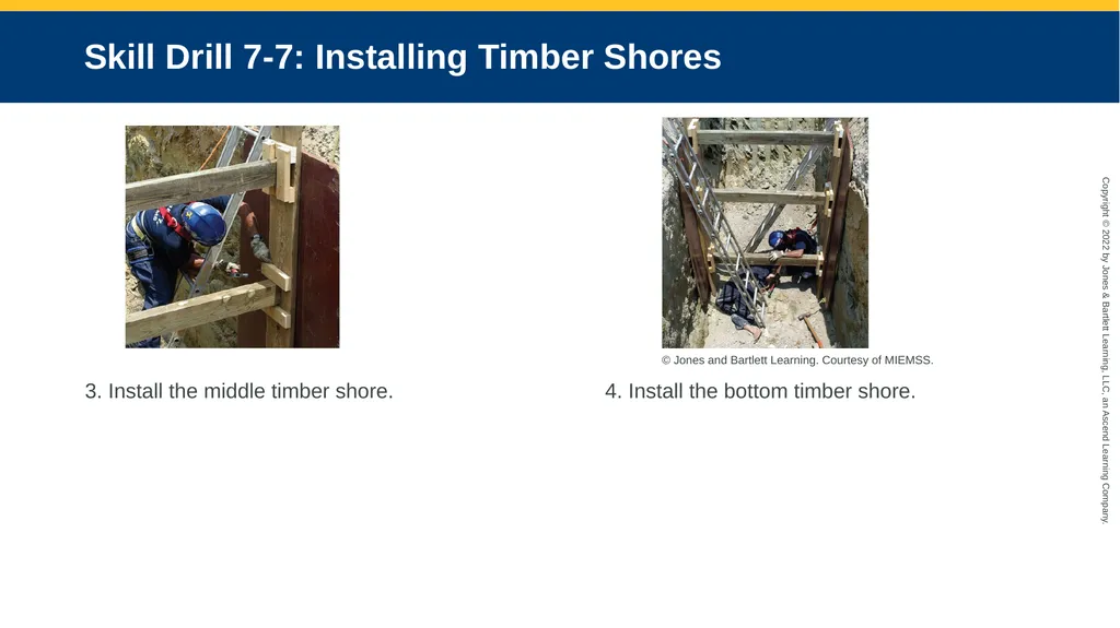
slide20. Skill Drill 7-7: Installing Timber Shores 3. Install the middle timber shore. 4. Install the bottom timber shore. © Jones and Bartlett Learning. Courtesy of MIEMSS.<br>
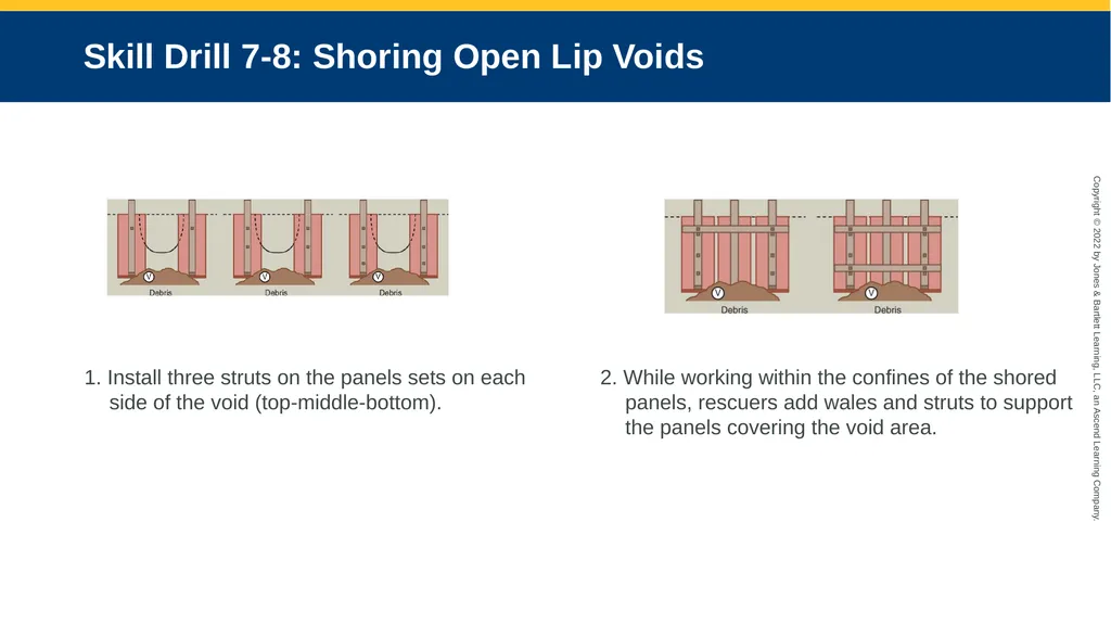
slide21. Skill Drill 7-8: Shoring Open Lip Voids 1. Install three struts on the panels sets on each side of the void (top-middle-bottom). 2. While working within the confines of the shored panels, rescuers add wales and struts to support the panels covering the void area.<br>
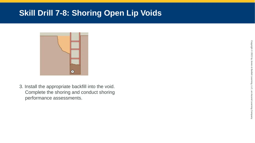
slide22. Skill Drill 7-8: Shoring Open Lip Voids 3. Install the appropriate backfill into the void. Complete the shoring and conduct shoring performance assessments.<br>
slide2. Skill Drill 7-1: Installing Ground Pads 1. When a spoil pile interferes with the placement of lip protection, the best solution is to begin by removing the spoil while standing on a 2 foot (0.6 m)–wide ground pad (either two 2 x 12 [0.6 x 3.6 m] or 2 x 8 [0.6 x 2.4 m] boards, or a 2 x 4 [0.6 x 1.2 m] section of plywood). After determining that the lip is stable enough for ground pad use, clear an area about 30 inches (0.7 m) back from the lip and as far forward as your shovel will reach. Rescuers should not walk or stand closer than 4 feet (1.2 m) from the trench wall on a section of unprotected trench lip.<br>
slide3. Skill Drill 7-1: Installing Ground Pads 2. After clearing the spoil pile, step back and move the ground pad forward. Continue shoveling and advancing the ground pad forward. Be sure not to step off the ground pad onto an unprotected lip and avoid standing and walking on the spoil pile.<br>
slide4. Skill Drill 7-1: Installing Ground Pads 3. Repeat Step 2 until enough of the spoil pile has been removed to allow the ground pad to protect the lip in the rescue area. The “rescue area” is generally considered to be 6 to 8 feet (1.8 and 2.4 m) on both sides of the trapped victim. With a spoil pile obstruction, a larger walkway may need to be cleared and protected with ground pads in order to safely access the rescue area. Courtesy of Ron Zawlocki.<br>
slide5. Skill Drill 7-2: Installing Lip Bridges 1. Place two ground pads on each side of the trench an equal distance (6–8 feet [(1.8–2.4 m)]) from the victim’s head/chest. When using lip bridges, it is acceptable for adjacent ground pads to meet at the victim’s location because all loads will be carried by the lip bridges.<br>
slide6. Skill Drill 7-2: Installing Lip Bridges 2. Place lip bridge supports (6 × 6 inches) on pad at least 4 feet (1.2 m) from the trench wall. 3. Place girders across the trench on the supports. Courtesy of Ron Zawlocki.<br>
slide7. Skill Drill 7-2: Installing Lip Bridges 4. Place platforms on the girders and slide the platform to the edge of the trench. Courtesy of Ron Zawlocki.<br>
slide8. Skill Drill 7-3: One-Side Panel Installation 1. Place two 4 × 4-inch timber rails (about 18 inches [46 cm] apart) in the trench so the bottoms of the rails create a designated destination for the strongback on the panel. The rails will go from the accessible trench lip to the toe on the opposite wall.<br>
slide9. Skill Drill 7-3: One-Side Panel Installation 2. Place a roped panel with the strongback facing down on the lip protection and slide it out using the lifting ropes for control; lower the panel onto and then down the rails.<br>
slide10. Skill Drill 7-3: One-Side Panel Installation 3. The panel can then be pushed or pulled to the opposite side using ropes or a pike pole where a member of the panel team will stand it up on the trench wall and hold it until the opposing panel and a strut can be put in place. 4. After removing the rails, the panel directly across the trench from the first panel will be lowered and positioned from the strong side. These “primary panels” should have struts installed as soon as possible to protect the victim from subsequent collapse. Repeat steps 1 to 4 to install the “secondary panels.” In a straight (nonintersecting) trench up to 8 feet (2.4 m) deep, the minimum recommended panels sets are three (six panels). © Jones and Bartlett Learning. Courtesy of MIEMSS.<br>
slide11. Skill Drill 7-4: Two-Side Panel Installation 1. Orient the panel so the strongback will face the interior of the trench. Place the panel on the trench lip protection and tip the bottom of the panel into the trench. 2. The two rescuers at the sides of the panel will use the ropes to lower the panel into the trench. The rescue in the center will push out on the top (this action brings the bottom of the panel to the trench wall) so that the panel is set tightly against the trench wall in the desired location.<br>
slide12. Skill Drill 7-4: Two-Side Panel Installation 3. Repeat this procedure from the lip protection on the opposite wall and position the second panel directly across from the first. Repeat steps 1 to 4 to install the “secondary panels.” In a straight (nonintersecting) trench up to 8 feet (2.4 m) deep, the minimum recommended panels sets are three (six panels). Courtesy of Ron Zawlocki.<br>
slide13. Skill Drill 7-5: Installing Pneumatic Struts Without Entering the Trench 1. The officer takes a position at the end of the trench. The controller (shooter) works on lip protection near the primary panel set. Two strut handlers work on lip protection from both sides of the trench. The controller connects the air hose to the strut and adjusts the regulator to the proper pressure to achieve the proper activation force. 2. Each strut handler attaches a rope to the strut. (It is advisable to use different colored ropes on each end of the strut to ease commands to raise and lower.) The strut handlers position themselves across the trench from each other at the primary panel set and use the ropes to lower the strut to the proper position and verify the strut is level and perpendicular (within 10 degrees) to the trench walls.<br>
slide14. Skill Drill 7-5: Installing Pneumatic Struts Without Entering the Trench 3. The officer acts as a spotter at the end of the trench to determine whether the shore is level (within 10 degrees) and in the correct location (depth). The handlers determine when the strut is aligned across the trench. The officer asks the handlers if they have aligned the strut: “Handlers ready?” After telling the controller the desired pressure of the strut, the officer gives the command, “Shoot and hold.” 4. After the strut has been shot and is in proper position, the strut collars are locked. If not using automatic locking struts, the strut handler on the collar side of the trench locks the collar with the collar-locking tool. When the collar has been locked, the strut handler tells the officer, “Collar locked.” With the collar locked, the strut is at its strongest point. Air pressure is no longer needed and the officer tells the controller “Down on air” and all air is released from the strut.<br>
slide15. Skill Drill 7-5: Installing Pneumatic Struts Without Entering the Trench 5. The process is repeated to install all needed struts on the primary panel set. Using struts with collars that can be locked without entering the trench can allow an entire rescue shoring system to be installed without exposing rescuers to the risk associated with collapse. Using the same procedures, additional shoring (panels and struts) can be added to expand the safe area in the trench. 6. A rescuer, equipped with a hammer and nails, enters the trench on a ladder placed within the shored panel area and installs two nails to all strut bases. Strut bases are nailed to the strongbacks (from top to bottom) by a rescuer climbing down a ladder.<br>
slide16. Skill Drill 7-6: Installing Pneumatic Struts With Entry Operations 1. Connect the air system to the strut, and set the regulator to achieve the proper activation force. 2. Two strut handlers work on lip protection on opposite sides of the trench behind the primary panels. They lower the shore into place using ropes attached to either end (it is advised to use different colored ropes on each end the ease commands to raise and lower). Verify that the strut is perpendicular to the trench walls.<br>
slide17. Skill Drill 7-6: Installing Pneumatic Struts With Entry Operations 3. When the strut is lined up in the proper place (usually determined best by the safety trench officer positioned at the end of the trench), the installer gives the signal to shoot and hold the shore. 4. The shooter activates the air at the pressure recommended by a professional engineer or the manufacturer’s tabulated data that is specific to soil conditions, including collapsed trench walls. This extends the strut and creates pressure on the trench wall.<br>
slide18. Skill Drill 7-6: Installing Pneumatic Struts With Entry Operations 5. An installer enters the trench on a ladder and manually locks the strut. With the collar locked, the strut is at its strongest point. 6. After securing the strut manually, the installer nails the strut bases to the strongbacks and then says, “Release” (to release the pressure). The air hose is then removed and placed on another strut as needed. Following the installation of lip protection and with panels placed tightly against the wall, the shoring team will install timber struts.<br>
slide19. Skill Drill 7-7: Installing Timber Shores 1. After the timber shore has been measured and cut, install the top timber. 2. Minimize the time the installer spends on the ladder. Strut handlers can assist the installer by lowering the timber with ropes to the designated spot. After the strut is installed, it must be secured to the strongback with nails. Use scabs to secure all timber struts.<br>
slide20. Skill Drill 7-7: Installing Timber Shores 3. Install the middle timber shore. 4. Install the bottom timber shore. © Jones and Bartlett Learning. Courtesy of MIEMSS.<br>
slide21. Skill Drill 7-8: Shoring Open Lip Voids 1. Install three struts on the panels sets on each side of the void (top-middle-bottom). 2. While working within the confines of the shored panels, rescuers add wales and struts to support the panels covering the void area.<br>
slide22. Skill Drill 7-8: Shoring Open Lip Voids 3. Install the appropriate backfill into the void. Complete the shoring and conduct shoring performance assessments.<br>