
Clark’s paper 1 Primary goal: Multiplexed use of
PC
Published · 51 slides · 0 views

1 / 1
Description
Clarks paper 1 Primary goal: Multiplexed use of existing (disparate) communication networks, separately administered Secondary goals: Priority order shaped the Internet Make it work now, worry about accounting later (but make it cheap to
Related Topics
Share
Embed code
Download this presentation From Below
"Clark’s paper 1 Primary goal: Multiplexed use of" is the property of its rightful owner. Permission is granted to download and print the materials on this website for personal, non-commercial use only, and to display it on your personal computer provided you do not modify the materials and that you retain all copyright notices contained in the materials. By downloading content from our website, you accept the terms of this agreement.
Presentation Transcript
01
Clark’s paper 1 Primary goal: Multiplexed use of existing (disparate) communication networks, separately administered
Secondary goals: Priority order shaped the Internet
Make it work now, worry about accounting later (but make it cheap to build)
Keep it simple, but know that it might be less efficient<br>
Secondary goals: Priority order shaped the Internet
Make it work now, worry about accounting later (but make it cheap to build)
Keep it simple, but know that it might be less efficient<br>
02
CS 4700 / CS 5700
Network Fundamentals Revised 9/14/20 Lecture 6: Data Link
(The Cocktail Party Conversation)<br>
(The Cocktail Party Conversation)<br>
03
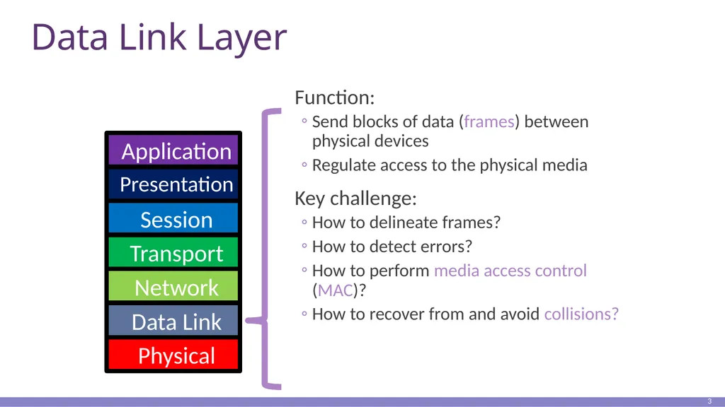
Data Link Layer Function:
Send blocks of data (frames) between physical devices
Regulate access to the physical media
Key challenge:
How to delineate frames?
How to detect errors?
How to perform media access control (MAC)?
How to recover from and avoid collisions? 3 Application Presentation Session Transport Network Data Link Physical<br>
Send blocks of data (frames) between physical devices
Regulate access to the physical media
Key challenge:
How to delineate frames?
How to detect errors?
How to perform media access control (MAC)?
How to recover from and avoid collisions? 3 Application Presentation Session Transport Network Data Link Physical<br>
04
Outline Framing
Error Checking and Reliability
Media Access Control
802.3 Ethernet
802.11 Wifi 4<br>
Error Checking and Reliability
Media Access Control
802.3 Ethernet
802.11 Wifi 4<br>
05
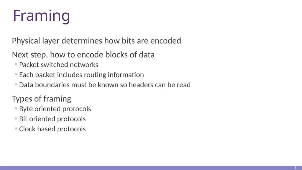
Framing Physical layer determines how bits are encoded
Next step, how to encode blocks of data
Packet switched networks
Each packet includes routing information
Data boundaries must be known so headers can be read
Types of framing
Byte oriented protocols
Bit oriented protocols
Clock based protocols 5<br>
Next step, how to encode blocks of data
Packet switched networks
Each packet includes routing information
Data boundaries must be known so headers can be read
Types of framing
Byte oriented protocols
Bit oriented protocols
Clock based protocols 5<br>
06
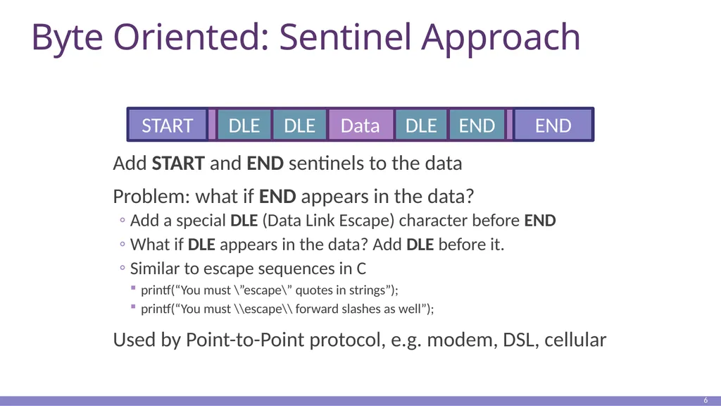
Byte Oriented: Sentinel Approach Add START and END sentinels to the data
Problem: what if END appears in the data?
Add a special DLE (Data Link Escape) character before END
What if DLE appears in the data? Add DLE before it.
Similar to escape sequences in C
printf(“You must \”escape\” quotes in strings”);
printf(“You must \\escape\\ forward slashes as well”);
Used by Point-to-Point protocol, e.g. modem, DSL, cellular 6 Data START END END DLE DLE DLE<br>
Problem: what if END appears in the data?
Add a special DLE (Data Link Escape) character before END
What if DLE appears in the data? Add DLE before it.
Similar to escape sequences in C
printf(“You must \”escape\” quotes in strings”);
printf(“You must \\escape\\ forward slashes as well”);
Used by Point-to-Point protocol, e.g. modem, DSL, cellular 6 Data START END END DLE DLE DLE<br>
07
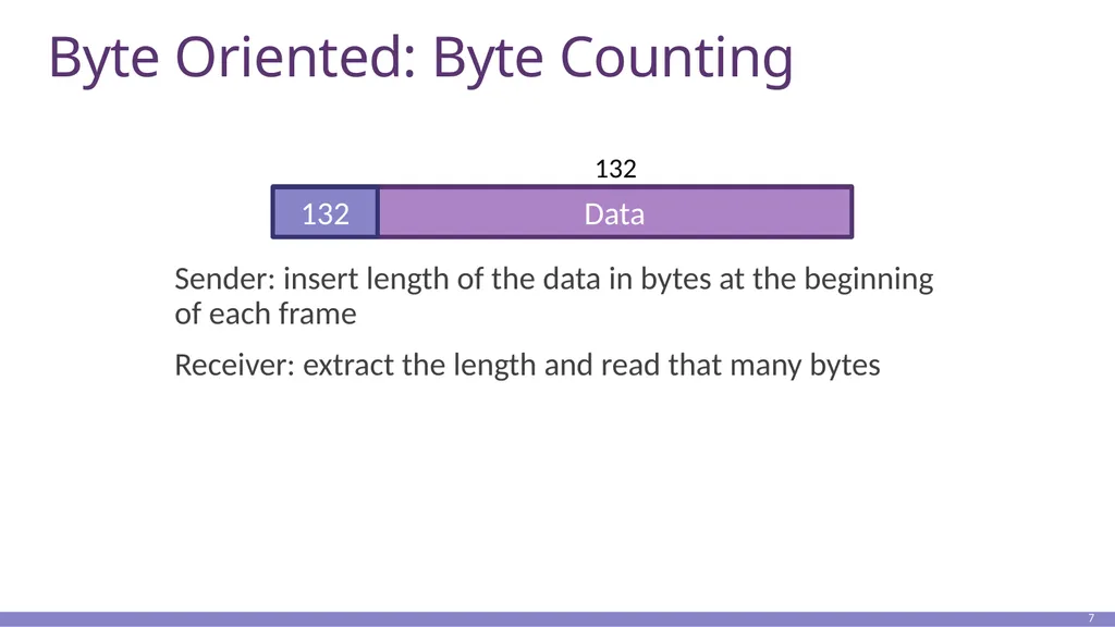
Byte Oriented: Byte Counting Sender: insert length of the data in bytes at the beginning of each frame
Receiver: extract the length and read that many bytes 7 Data 132 132<br>
Receiver: extract the length and read that many bytes 7 Data 132 132<br>
08
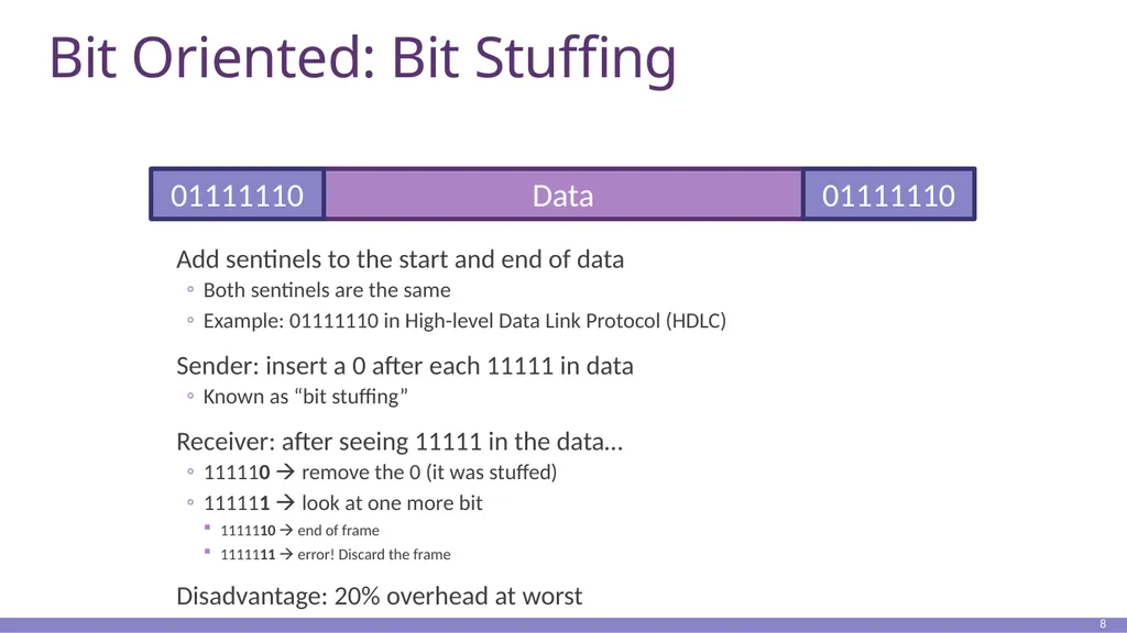
Bit Oriented: Bit Stuffing Add sentinels to the start and end of data
Both sentinels are the same
Example: 01111110 in High-level Data Link Protocol (HDLC)
Sender: insert a 0 after each 11111 in data
Known as “bit stuffing”
Receiver: after seeing 11111 in the data…
111110 remove the 0 (it was stuffed)
111111 look at one more bit
1111110 end of frame
1111111 error! Discard the frame
Disadvantage: 20% overhead at worst 8 Data 01111110 01111110<br>
Both sentinels are the same
Example: 01111110 in High-level Data Link Protocol (HDLC)
Sender: insert a 0 after each 11111 in data
Known as “bit stuffing”
Receiver: after seeing 11111 in the data…
111110 remove the 0 (it was stuffed)
111111 look at one more bit
1111110 end of frame
1111111 error! Discard the frame
Disadvantage: 20% overhead at worst 8 Data 01111110 01111110<br>
09
Clock-based Framing: SONET Synchronous Optical Network
Transmission over very fast optical links
STS-n, e.g. STS-1: 51.84 Mbps, STS-768: 36.7 Gbps
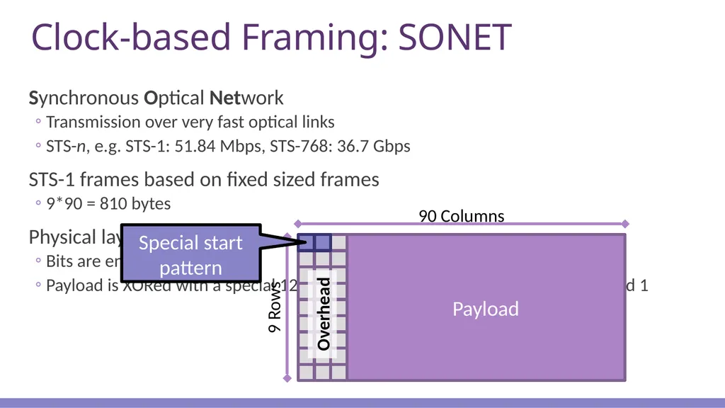
STS-1 frames based on fixed sized frames
9*90 = 810 bytes
Physical layer details
Bits are encoded using NRZ
Payload is XORed with a special 127-bit pattern to avoid long sequences of 0 and 1 9 90 Columns 9 Rows<br>
Transmission over very fast optical links
STS-n, e.g. STS-1: 51.84 Mbps, STS-768: 36.7 Gbps
STS-1 frames based on fixed sized frames
9*90 = 810 bytes
Physical layer details
Bits are encoded using NRZ
Payload is XORed with a special 127-bit pattern to avoid long sequences of 0 and 1 9 90 Columns 9 Rows<br>
10
Outline Framing
Error Checking and Reliability
Media Access Control
802.3 Ethernet
802.11 Wifi 10<br>
Error Checking and Reliability
Media Access Control
802.3 Ethernet
802.11 Wifi 10<br>
11
Dealing with Noise The physical world is inherently noisy
Interference from electrical cables
Cross-talk from radio transmissions, microwave ovens
Solar storms
How to detect bit-errors in transmissions?
How to recover from errors? 11<br>
Interference from electrical cables
Cross-talk from radio transmissions, microwave ovens
Solar storms
How to detect bit-errors in transmissions?
How to recover from errors? 11<br>
12
Naïve Error Detection Idea: send two copies of each frame
if (memcmp(frame1, frame2) != 0) { OH NOES, AN ERROR! }
Why is this a bad idea?
Extremely high overhead
Poor protection against errors
Twice the data means twice the chance for bit errors 12<br>
if (memcmp(frame1, frame2) != 0) { OH NOES, AN ERROR! }
Why is this a bad idea?
Extremely high overhead
Poor protection against errors
Twice the data means twice the chance for bit errors 12<br>
13
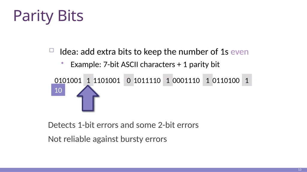
Parity Bits Detects 1-bit errors and some 2-bit errors
Not reliable against bursty errors 13 Idea: add extra bits to keep the number of 1s even
Example: 7-bit ASCII characters + 1 parity bit 0101001 1 0 1 1 1 1011110 0110100 1101001 0001110 1 10<br>
Not reliable against bursty errors 13 Idea: add extra bits to keep the number of 1s even
Example: 7-bit ASCII characters + 1 parity bit 0101001 1 0 1 1 1 1011110 0110100 1101001 0001110 1 10<br>
14
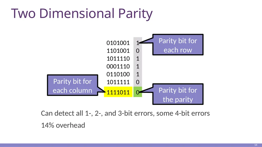
Two Dimensional Parity Can detect all 1-, 2-, and 3-bit errors, some 4-bit errors
14% overhead 14 0101001
1101001
1011110
0001110
0110100
1011111 1
0
1
1
1
0 1111011 0<br>
14% overhead 14 0101001
1101001
1011110
0001110
0110100
1011111 1
0
1
1
1
0 1111011 0<br>
15
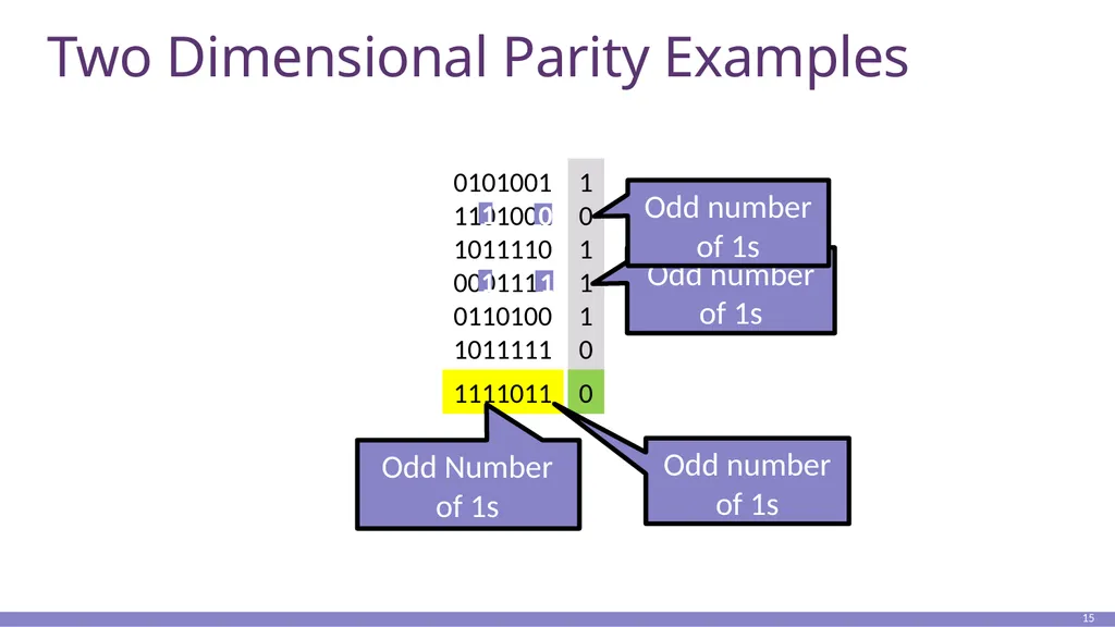
Two Dimensional Parity Examples 15 0101001
1101001
1011110
0001110
0110100
1011111 1
0
1
1
1
0 1111011 0<br>
1101001
1011110
0001110
0110100
1011111 1
0
1
1
1
0 1111011 0<br>
16
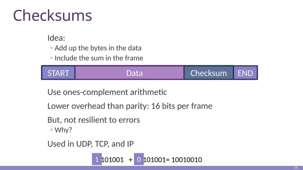
Checksums Idea:
Add up the bytes in the data
Include the sum in the frame
Use ones-complement arithmetic
Lower overhead than parity: 16 bits per frame
But, not resilient to errors
Why?
Used in UDP, TCP, and IP 16 Data START END Checksum 0101001 1101001= 10010010 + 0 1<br>
Add up the bytes in the data
Include the sum in the frame
Use ones-complement arithmetic
Lower overhead than parity: 16 bits per frame
But, not resilient to errors
Why?
Used in UDP, TCP, and IP 16 Data START END Checksum 0101001 1101001= 10010010 + 0 1<br>
17
Cyclic Redundancy Check (CRC) Uses field theory to compute a semi-unique value for a given message
Much better performance than previous approaches
Fixed size overhead per frame (usually 32-bits)
Quick to implement in hardware
Only 1 in 232 chance of missing an error with 32-bit CRC
Details are in the book/on Wikipedia 17<br>
Much better performance than previous approaches
Fixed size overhead per frame (usually 32-bits)
Quick to implement in hardware
Only 1 in 232 chance of missing an error with 32-bit CRC
Details are in the book/on Wikipedia 17<br>
18
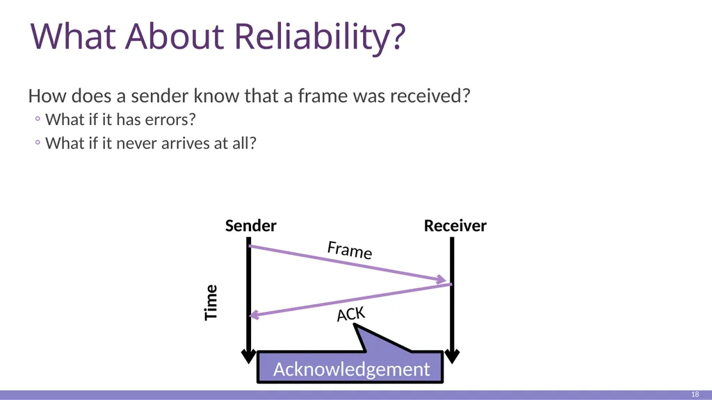
What About Reliability? How does a sender know that a frame was received?
What if it has errors?
What if it never arrives at all? 18 Sender Receiver Time<br>
What if it has errors?
What if it never arrives at all? 18 Sender Receiver Time<br>
19
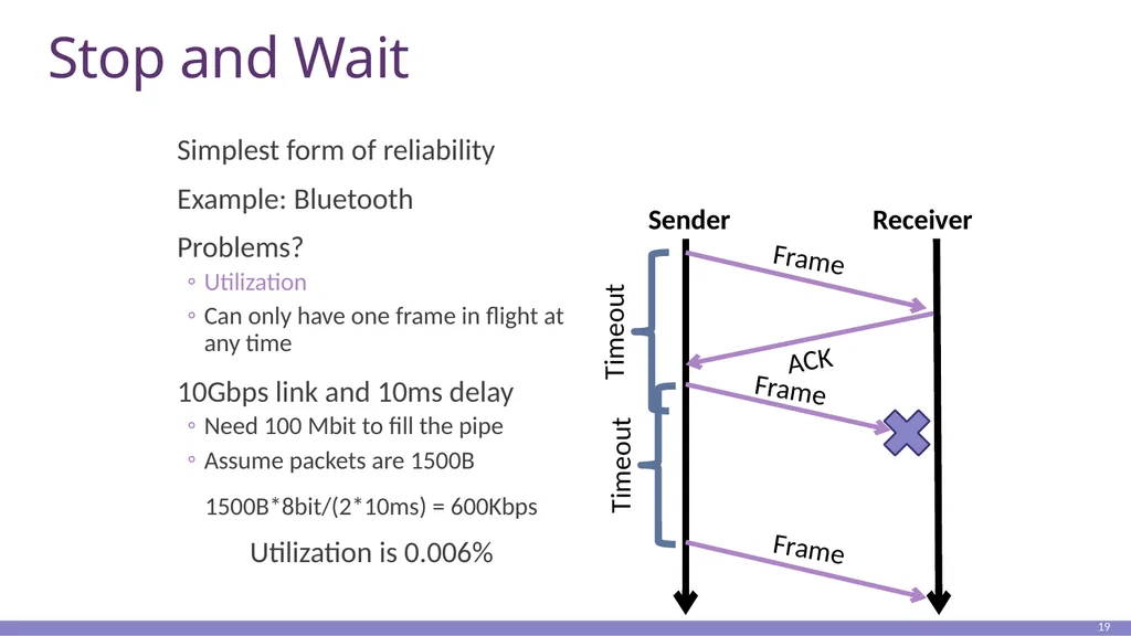
Stop and Wait Simplest form of reliability
Example: Bluetooth
Problems?
Utilization
Can only have one frame in flight at any time
10Gbps link and 10ms delay
Need 100 Mbit to fill the pipe
Assume packets are 1500B
1500B*8bit/(2*10ms) = 600Kbps
Utilization is 0.006% 19 Sender Receiver<br>
Example: Bluetooth
Problems?
Utilization
Can only have one frame in flight at any time
10Gbps link and 10ms delay
Need 100 Mbit to fill the pipe
Assume packets are 1500B
1500B*8bit/(2*10ms) = 600Kbps
Utilization is 0.006% 19 Sender Receiver<br>
20
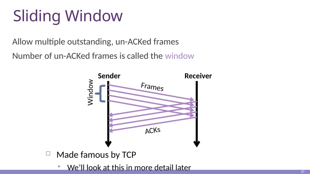
Sliding Window Allow multiple outstanding, un-ACKed frames
Number of un-ACKed frames is called the window 20 Sender Receiver ACKs Made famous by TCP
We’ll look at this in more detail later<br>
Number of un-ACKed frames is called the window 20 Sender Receiver ACKs Made famous by TCP
We’ll look at this in more detail later<br>
21
Should We Error Check in the Data Link? Recall the End-to-End Argument
Cons:
Error free transmission cannot be guaranteed
Not all applications want this functionality
Error checking adds CPU and packet size overhead
Error recovery requires buffering
Pros:
Potentially better performance than app-level error checking
Data link error checking in practice
Most useful over lossy links
Wifi, cellular, satellite 21<br>
Cons:
Error free transmission cannot be guaranteed
Not all applications want this functionality
Error checking adds CPU and packet size overhead
Error recovery requires buffering
Pros:
Potentially better performance than app-level error checking
Data link error checking in practice
Most useful over lossy links
Wifi, cellular, satellite 21<br>
22
Outline Framing
Error Checking and Reliability
Media Access Control
802.3 Ethernet
802.11 Wifi 22<br>
Error Checking and Reliability
Media Access Control
802.3 Ethernet
802.11 Wifi 22<br>
23
What is Media Access? Ethernet and Wifi are both multi-access technologies
Broadcast medium, shared by many hosts
Simultaneous transmissions cause collisions
This destroys the data
Media Access Control (MAC) protocols are required
Rules on how to share the medium
Strategies for detecting, avoiding, and recovering from collisions 23<br>
Broadcast medium, shared by many hosts
Simultaneous transmissions cause collisions
This destroys the data
Media Access Control (MAC) protocols are required
Rules on how to share the medium
Strategies for detecting, avoiding, and recovering from collisions 23<br>
24
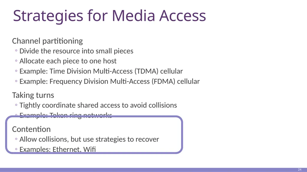
Strategies for Media Access Channel partitioning
Divide the resource into small pieces
Allocate each piece to one host
Example: Time Division Multi-Access (TDMA) cellular
Example: Frequency Division Multi-Access (FDMA) cellular
Taking turns
Tightly coordinate shared access to avoid collisions
Example: Token ring networks
Contention
Allow collisions, but use strategies to recover
Examples: Ethernet, Wifi 24<br>
Divide the resource into small pieces
Allocate each piece to one host
Example: Time Division Multi-Access (TDMA) cellular
Example: Frequency Division Multi-Access (FDMA) cellular
Taking turns
Tightly coordinate shared access to avoid collisions
Example: Token ring networks
Contention
Allow collisions, but use strategies to recover
Examples: Ethernet, Wifi 24<br>
25
Contention MAC Goals Share the medium
Two hosts sending at the same time collide, thus causing interference
If no host sends, channel is idle
Thus, want one user sending at any given time
High utilization
TDMA is low utilization
Just like a circuit switched network
Simple, distributed algorithm
Multiple hosts that cannot directly coordinate
No fancy (complicated) token-passing schemes 25<br>
Two hosts sending at the same time collide, thus causing interference
If no host sends, channel is idle
Thus, want one user sending at any given time
High utilization
TDMA is low utilization
Just like a circuit switched network
Simple, distributed algorithm
Multiple hosts that cannot directly coordinate
No fancy (complicated) token-passing schemes 25<br>
26
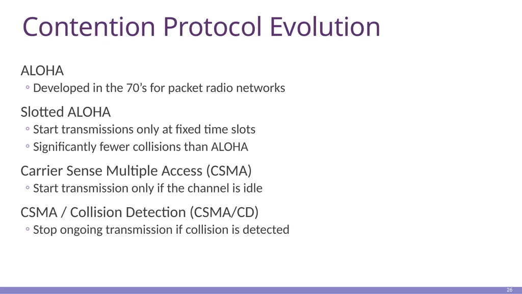
Contention Protocol Evolution ALOHA
Developed in the 70’s for packet radio networks
Slotted ALOHA
Start transmissions only at fixed time slots
Significantly fewer collisions than ALOHA
Carrier Sense Multiple Access (CSMA)
Start transmission only if the channel is idle
CSMA / Collision Detection (CSMA/CD)
Stop ongoing transmission if collision is detected 26<br>
Developed in the 70’s for packet radio networks
Slotted ALOHA
Start transmissions only at fixed time slots
Significantly fewer collisions than ALOHA
Carrier Sense Multiple Access (CSMA)
Start transmission only if the channel is idle
CSMA / Collision Detection (CSMA/CD)
Stop ongoing transmission if collision is detected 26<br>
27
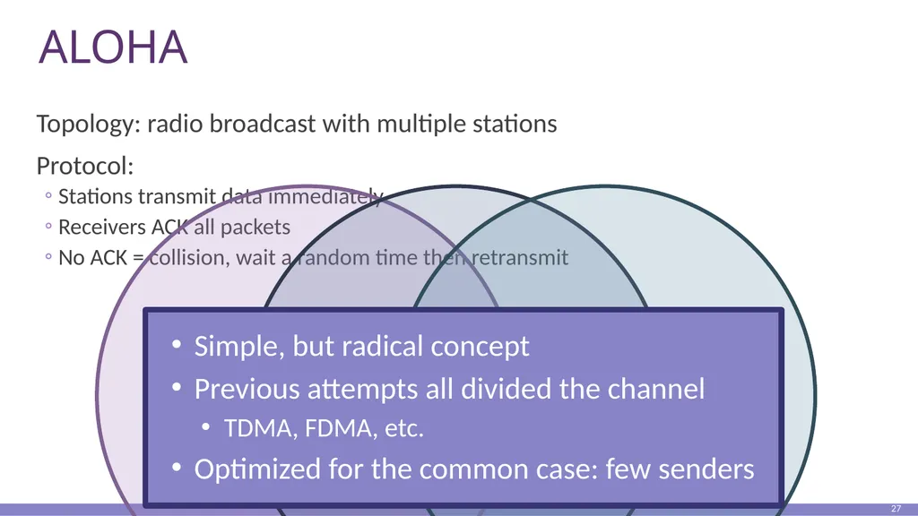
ALOHA Topology: radio broadcast with multiple stations
Protocol:
Stations transmit data immediately
Receivers ACK all packets
No ACK = collision, wait a random time then retransmit 27<br>
Protocol:
Stations transmit data immediately
Receivers ACK all packets
No ACK = collision, wait a random time then retransmit 27<br>
28
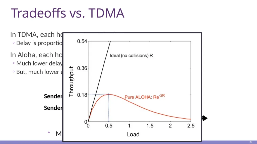
Tradeoffs vs. TDMA In TDMA, each host must wait for its turn
Delay is proportional to number of hosts
In Aloha, each host sends immediately
Much lower delay
But, much lower utilization 28 ALOHA Frame ALOHA Frame Time Sender A Sender B Maximum throughput is ~18% of channel capacity<br>
Delay is proportional to number of hosts
In Aloha, each host sends immediately
Much lower delay
But, much lower utilization 28 ALOHA Frame ALOHA Frame Time Sender A Sender B Maximum throughput is ~18% of channel capacity<br>
29
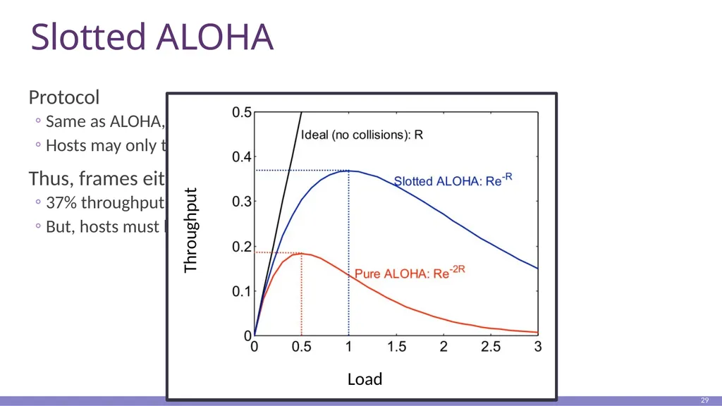
Slotted ALOHA Protocol
Same as ALOHA, except time is divided into slots
Hosts may only transmit at the beginning of a slot
Thus, frames either collide completely, or not at all
37% throughput vs. 18% for ALOHA
But, hosts must have synchronized clocks 29<br>
Same as ALOHA, except time is divided into slots
Hosts may only transmit at the beginning of a slot
Thus, frames either collide completely, or not at all
37% throughput vs. 18% for ALOHA
But, hosts must have synchronized clocks 29<br>
30
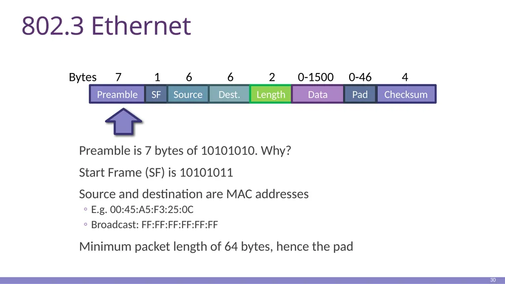
802.3 Ethernet Preamble is 7 bytes of 10101010. Why?
Start Frame (SF) is 10101011
Source and destination are MAC addresses
E.g. 00:45:A5:F3:25:0C
Broadcast: FF:FF:FF:FF:FF:FF
Minimum packet length of 64 bytes, hence the pad 30 Preamble SF Source Dest. Length 7 1 6 6 2 Bytes Data Checksum Pad 0-1500 0-46 4<br>
Start Frame (SF) is 10101011
Source and destination are MAC addresses
E.g. 00:45:A5:F3:25:0C
Broadcast: FF:FF:FF:FF:FF:FF
Minimum packet length of 64 bytes, hence the pad 30 Preamble SF Source Dest. Length 7 1 6 6 2 Bytes Data Checksum Pad 0-1500 0-46 4<br>
31
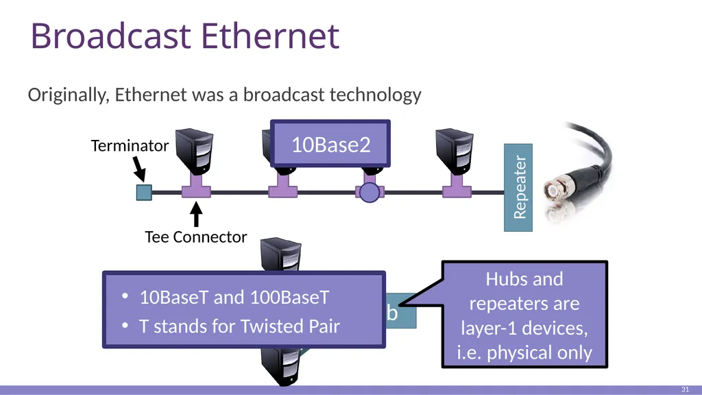
Broadcast Ethernet Originally, Ethernet was a broadcast technology 31 Tee Connector Terminator Hub Repeater<br>
32
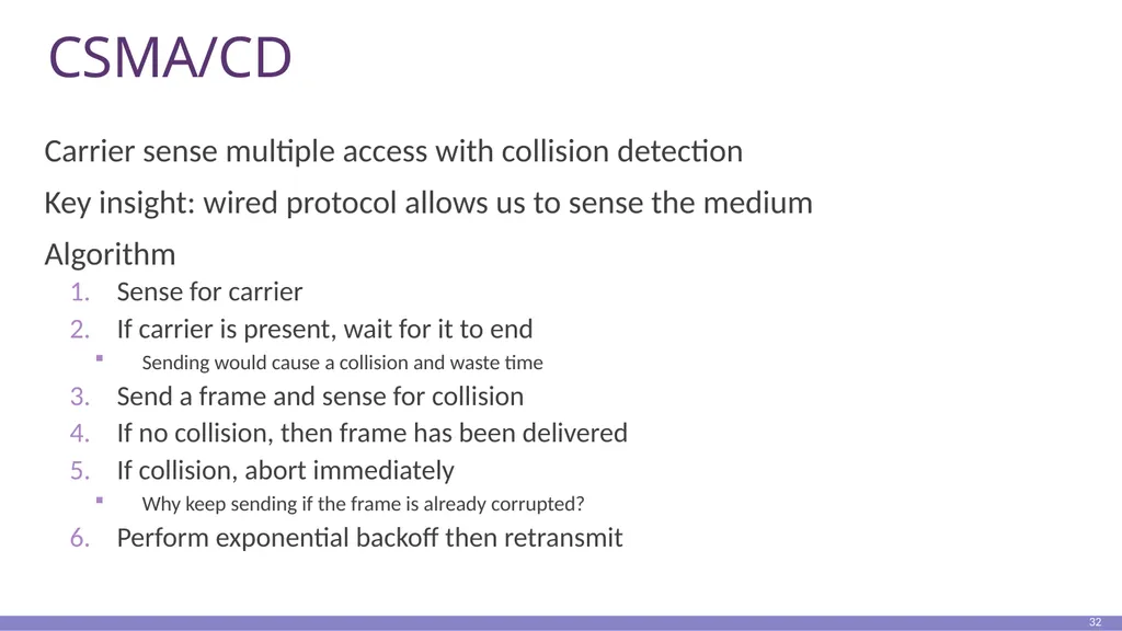
CSMA/CD Carrier sense multiple access with collision detection
Key insight: wired protocol allows us to sense the medium
Algorithm
Sense for carrier
If carrier is present, wait for it to end
Sending would cause a collision and waste time
Send a frame and sense for collision
If no collision, then frame has been delivered
If collision, abort immediately
Why keep sending if the frame is already corrupted?
Perform exponential backoff then retransmit 32<br>
Key insight: wired protocol allows us to sense the medium
Algorithm
Sense for carrier
If carrier is present, wait for it to end
Sending would cause a collision and waste time
Send a frame and sense for collision
If no collision, then frame has been delivered
If collision, abort immediately
Why keep sending if the frame is already corrupted?
Perform exponential backoff then retransmit 32<br>
33
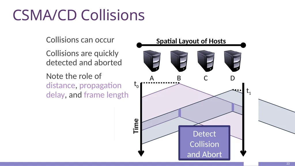
CSMA/CD Collisions 33 Time t0 t1 Spatial Layout of Hosts Collisions can occur
Collisions are quickly detected and aborted
Note the role of distance, propagation delay, and frame length<br>
Collisions are quickly detected and aborted
Note the role of distance, propagation delay, and frame length<br>
34
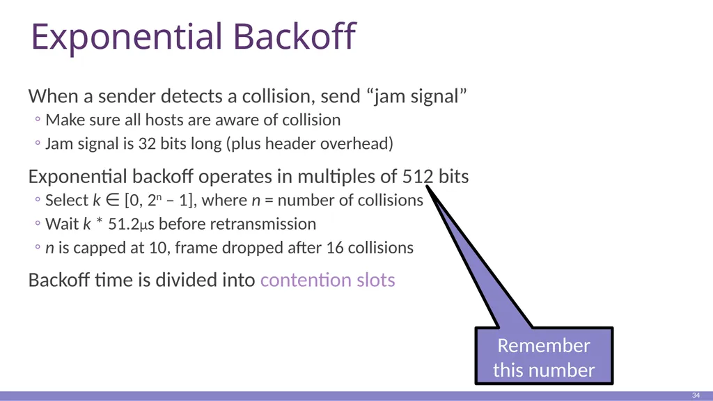
Exponential Backoff When a sender detects a collision, send “jam signal”
Make sure all hosts are aware of collision
Jam signal is 32 bits long (plus header overhead)
Exponential backoff operates in multiples of 512 bits
Select k ∈ [0, 2n – 1], where n = number of collisions
Wait k * 51.2µs before retransmission
n is capped at 10, frame dropped after 16 collisions
Backoff time is divided into contention slots 34<br>
Make sure all hosts are aware of collision
Jam signal is 32 bits long (plus header overhead)
Exponential backoff operates in multiples of 512 bits
Select k ∈ [0, 2n – 1], where n = number of collisions
Wait k * 51.2µs before retransmission
n is capped at 10, frame dropped after 16 collisions
Backoff time is divided into contention slots 34<br>
35
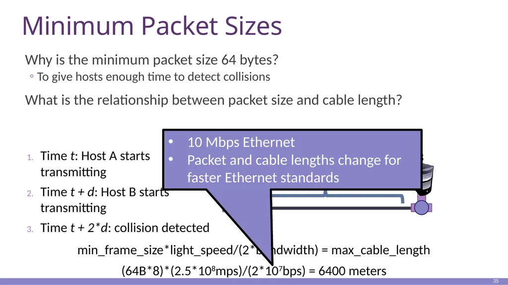
Minimum Packet Sizes Why is the minimum packet size 64 bytes?
To give hosts enough time to detect collisions
What is the relationship between packet size and cable length? 35 Propagation Delay (d) Time t: Host A starts transmitting
Time t + d: Host B starts transmitting
Time t + 2*d: collision detected A B min_frame_size*light_speed/(2*bandwidth) = max_cable_length
(64B*8)*(2.5*108mps)/(2*107bps) = 6400 meters<br>
To give hosts enough time to detect collisions
What is the relationship between packet size and cable length? 35 Propagation Delay (d) Time t: Host A starts transmitting
Time t + d: Host B starts transmitting
Time t + 2*d: collision detected A B min_frame_size*light_speed/(2*bandwidth) = max_cable_length
(64B*8)*(2.5*108mps)/(2*107bps) = 6400 meters<br>
36
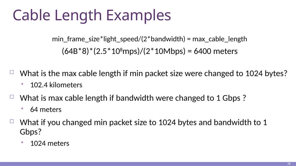
Cable Length Examples min_frame_size*light_speed/(2*bandwidth) = max_cable_length
(64B*8)*(2.5*108mps)/(2*10Mbps) = 6400 meters
What is the max cable length if min packet size were changed to 1024 bytes?
102.4 kilometers
What is max cable length if bandwidth were changed to 1 Gbps ?
64 meters
What if you changed min packet size to 1024 bytes and bandwidth to 1 Gbps?
1024 meters 36<br>
(64B*8)*(2.5*108mps)/(2*10Mbps) = 6400 meters
What is the max cable length if min packet size were changed to 1024 bytes?
102.4 kilometers
What is max cable length if bandwidth were changed to 1 Gbps ?
64 meters
What if you changed min packet size to 1024 bytes and bandwidth to 1 Gbps?
1024 meters 36<br>
37
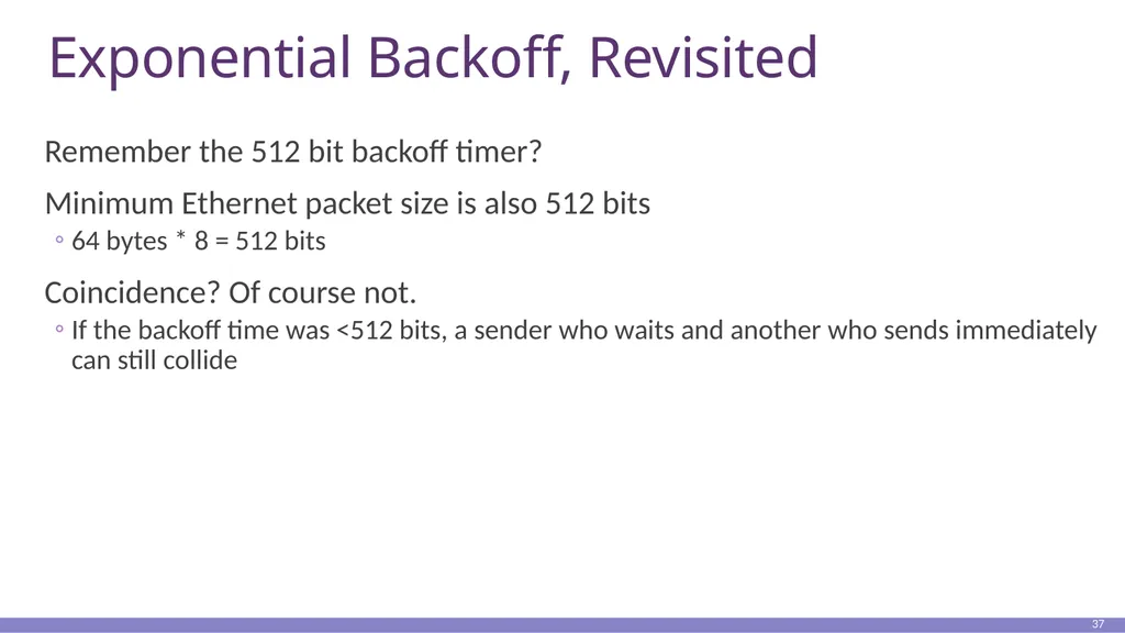
Exponential Backoff, Revisited Remember the 512 bit backoff timer?
Minimum Ethernet packet size is also 512 bits
64 bytes * 8 = 512 bits
Coincidence? Of course not.
If the backoff time was <512 bits, a sender who waits and another who sends immediately can still collide 37<br>
Minimum Ethernet packet size is also 512 bits
64 bytes * 8 = 512 bits
Coincidence? Of course not.
If the backoff time was <512 bits, a sender who waits and another who sends immediately can still collide 37<br>
38
Maximum Packet Size Maximum Transmission Unit (MTU): 1500 bytes
Pros:
Bit errors in long packets incur significant recovery penalty
Cons:
More bytes wasted on header information
Higher per packet processing overhead
Datacenters shifting towards Jumbo Frames
9000 bytes per packet 38<br>
Pros:
Bit errors in long packets incur significant recovery penalty
Cons:
More bytes wasted on header information
Higher per packet processing overhead
Datacenters shifting towards Jumbo Frames
9000 bytes per packet 38<br>
39
Long Live Ethernet Today’s Ethernet is switched
More on this later
1Gbit and 10Gbit Ethernet now common
100Gbit on the way
Uses same old packet header
Full duplex (send and receive at the same time)
Auto negotiating (backwards compatibility)
Can also carry power 39<br>
1Gbit and 10Gbit Ethernet now common
100Gbit on the way
Uses same old packet header
Full duplex (send and receive at the same time)
Auto negotiating (backwards compatibility)
Can also carry power 39<br>
40
Outline Framing
Error Checking and Reliability
Media Access Control
802.3 Ethernet
802.11 Wifi 40<br>
Error Checking and Reliability
Media Access Control
802.3 Ethernet
802.11 Wifi 40<br>
41
802.3 vs. Wireless Ethernet has one shared collision domain
All hosts on a LAN can observe all transmissions
Wireless radios have small range compared to overall system
Collisions are local
Collision are at the receiver, not the sender
Carrier sense (CS in CSMA) plays a different role
802.11 uses CSMA/CA not CSMA/CD
Collision avoidance, rather than collision detection 41<br>
All hosts on a LAN can observe all transmissions
Wireless radios have small range compared to overall system
Collisions are local
Collision are at the receiver, not the sender
Carrier sense (CS in CSMA) plays a different role
802.11 uses CSMA/CA not CSMA/CD
Collision avoidance, rather than collision detection 41<br>
42
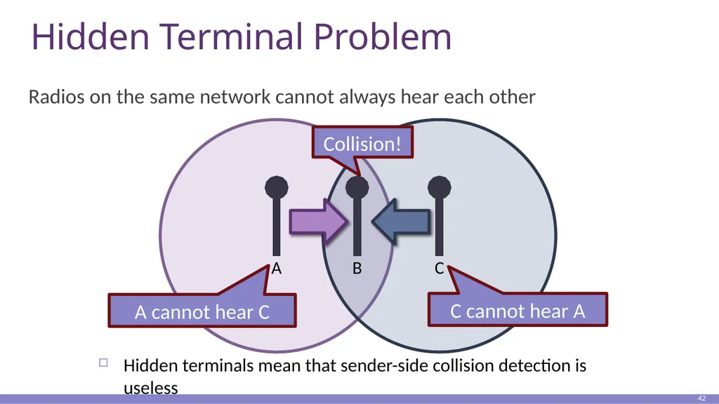
Hidden Terminal Problem Radios on the same network cannot always hear each other 42 Hidden terminals mean that sender-side collision detection is useless<br>
43
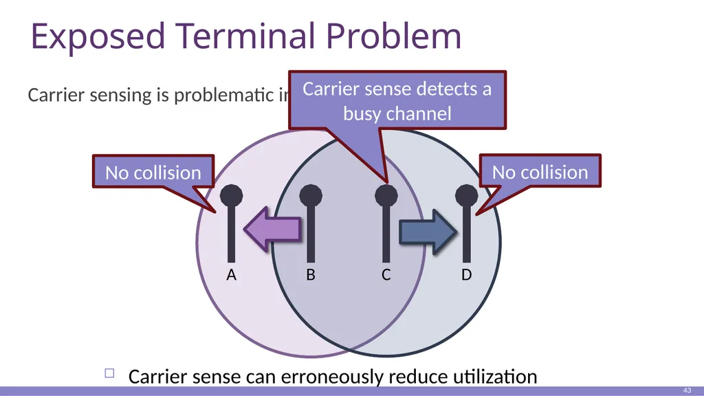
Exposed Terminal Problem Carrier sensing is problematic in wireless 43 Carrier sense can erroneously reduce utilization<br>
44
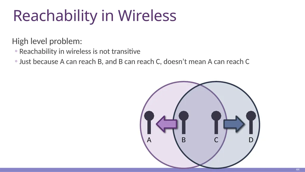
Reachability in Wireless High level problem:
Reachability in wireless is not transitive
Just because A can reach B, and B can reach C, doesn’t mean A can reach C 44<br>
Reachability in wireless is not transitive
Just because A can reach B, and B can reach C, doesn’t mean A can reach C 44<br>
45
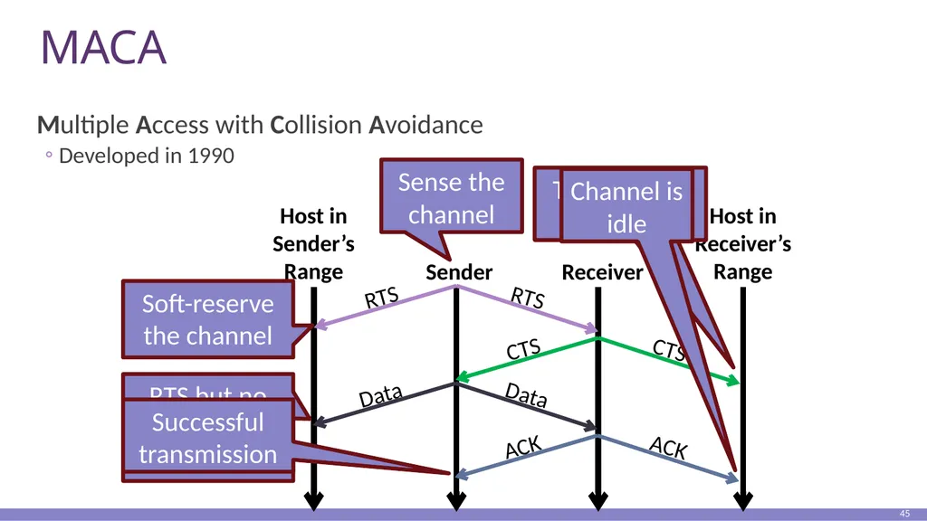
MACA Multiple Access with Collision Avoidance
Developed in 1990 45 Sender Receiver Host in
Receiver’s
Range Host in
Sender’s
Range<br>
Developed in 1990 45 Sender Receiver Host in
Receiver’s
Range Host in
Sender’s
Range<br>
46
Collisions in MACA What if sender does not receive CTS or ACK?
Assume collision
Enter exponential backoff mode 46<br>
Assume collision
Enter exponential backoff mode 46<br>
47
802.11b 802.11
Uses CSMA/CA, not MACA
802.11b
Introduced in 1999
Uses the unlicensed 2.4 Ghz band
Same band as cordless phones, microwave ovens
Complementary code keying (CCK) modulation scheme
5.5 and 11 Mbps data rates
Practical throughput with TCP is only 5.9 Mbps
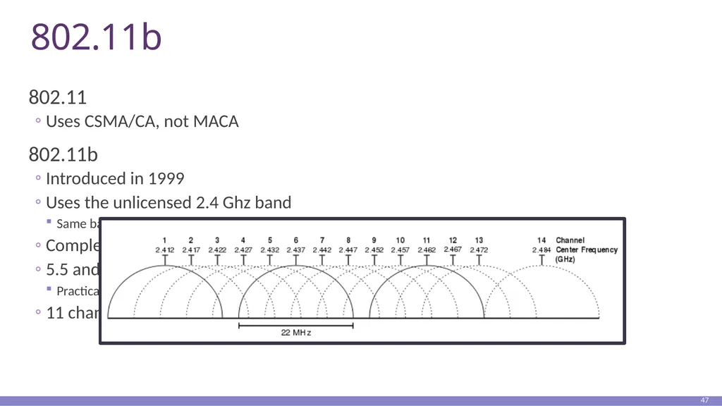
11 channels (in the US). Only 1, 6, and 11 are orthogonal 47<br>
Uses CSMA/CA, not MACA
802.11b
Introduced in 1999
Uses the unlicensed 2.4 Ghz band
Same band as cordless phones, microwave ovens
Complementary code keying (CCK) modulation scheme
5.5 and 11 Mbps data rates
Practical throughput with TCP is only 5.9 Mbps
11 channels (in the US). Only 1, 6, and 11 are orthogonal 47<br>
48
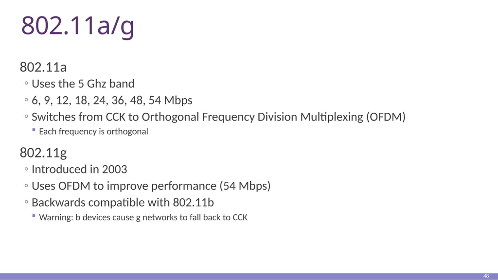
802.11a/g 802.11a
Uses the 5 Ghz band
6, 9, 12, 18, 24, 36, 48, 54 Mbps
Switches from CCK to Orthogonal Frequency Division Multiplexing (OFDM)
Each frequency is orthogonal
802.11g
Introduced in 2003
Uses OFDM to improve performance (54 Mbps)
Backwards compatible with 802.11b
Warning: b devices cause g networks to fall back to CCK 48<br>
Uses the 5 Ghz band
6, 9, 12, 18, 24, 36, 48, 54 Mbps
Switches from CCK to Orthogonal Frequency Division Multiplexing (OFDM)
Each frequency is orthogonal
802.11g
Introduced in 2003
Uses OFDM to improve performance (54 Mbps)
Backwards compatible with 802.11b
Warning: b devices cause g networks to fall back to CCK 48<br>
49
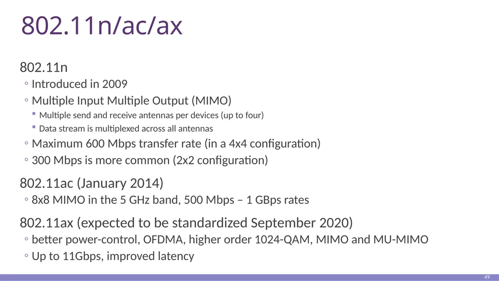
802.11n/ac/ax 802.11n
Introduced in 2009
Multiple Input Multiple Output (MIMO)
Multiple send and receive antennas per devices (up to four)
Data stream is multiplexed across all antennas
Maximum 600 Mbps transfer rate (in a 4x4 configuration)
300 Mbps is more common (2x2 configuration)
802.11ac (January 2014)
8x8 MIMO in the 5 GHz band, 500 Mbps – 1 GBps rates
802.11ax (expected to be standardized September 2020)
better power-control, OFDMA, higher order 1024-QAM, MIMO and MU-MIMO
Up to 11Gbps, improved latency 49<br>
Introduced in 2009
Multiple Input Multiple Output (MIMO)
Multiple send and receive antennas per devices (up to four)
Data stream is multiplexed across all antennas
Maximum 600 Mbps transfer rate (in a 4x4 configuration)
300 Mbps is more common (2x2 configuration)
802.11ac (January 2014)
8x8 MIMO in the 5 GHz band, 500 Mbps – 1 GBps rates
802.11ax (expected to be standardized September 2020)
better power-control, OFDMA, higher order 1024-QAM, MIMO and MU-MIMO
Up to 11Gbps, improved latency 49<br>
50
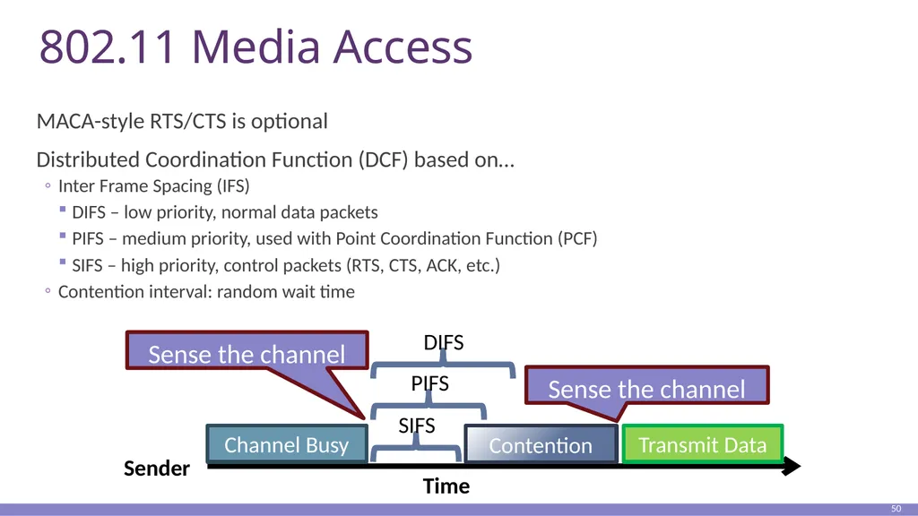
802.11 Media Access MACA-style RTS/CTS is optional
Distributed Coordination Function (DCF) based on…
Inter Frame Spacing (IFS)
DIFS – low priority, normal data packets
PIFS – medium priority, used with Point Coordination Function (PCF)
SIFS – high priority, control packets (RTS, CTS, ACK, etc.)
Contention interval: random wait time 50 Sender Time Channel Busy SIFS PIFS DIFS Contention Transmit Data<br>
Distributed Coordination Function (DCF) based on…
Inter Frame Spacing (IFS)
DIFS – low priority, normal data packets
PIFS – medium priority, used with Point Coordination Function (PCF)
SIFS – high priority, control packets (RTS, CTS, ACK, etc.)
Contention interval: random wait time 50 Sender Time Channel Busy SIFS PIFS DIFS Contention Transmit Data<br>
51
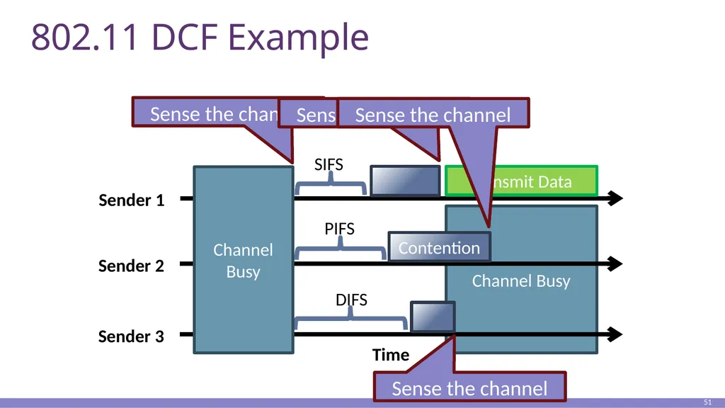
Channel Busy 802.11 DCF Example 51 Sender 1 Time SIFS PIFS DIFS Transmit Data Sender 2 Sender 3 Channel Busy Contention<br>
52
801.11 is Complicated We’ve only scratched the surface of 802.11
Association – how do clients connect to access points?
Scanning
What about roaming?
Variable sending rates to combat noisy channels
Infrastructure vs. ad-hoc vs. point-to-point
Mesh networks and mesh routing
Power saving optimizations
How do you sleep and also guarantee no lost messages?
Security and encryption (WEP, WAP, 802.11x)
This is why there are courses on wireless networking 52<br>
Association – how do clients connect to access points?
Scanning
What about roaming?
Variable sending rates to combat noisy channels
Infrastructure vs. ad-hoc vs. point-to-point
Mesh networks and mesh routing
Power saving optimizations
How do you sleep and also guarantee no lost messages?
Security and encryption (WEP, WAP, 802.11x)
This is why there are courses on wireless networking 52<br>