
Computer Architecture Prof. Dr. Nizamettin AYDIN
GB
Published · 60 slides · 0 views

1 / 1

Description
Computer Architecture Prof. Dr. Nizamettin AYDIN naydinyildiz.edu.tr nizamettinaydingmail.com http:www.yildiz.edu.trnaydin 1 External Memory 2 Outline Types of External Memory Magnetic Disk Magnetic Read and Write Mechanisms Data
Related Topics
Share
Embed code
Download this presentation From Below
"Computer Architecture Prof. Dr. Nizamettin AYDIN" is the property of its rightful owner. Permission is granted to download and print the materials on this website for personal, non-commercial use only, and to display it on your personal computer provided you do not modify the materials and that you retain all copyright notices contained in the materials. By downloading content from our website, you accept the terms of this agreement.
Presentation Transcript
01
Computer Architecture Prof. Dr. Nizamettin AYDIN
naydin@yildiz.edu.tr
nizamettinaydin@gmail.com
http://www.yildiz.edu.tr/~naydin 1<br>
naydin@yildiz.edu.tr
nizamettinaydin@gmail.com
http://www.yildiz.edu.tr/~naydin 1<br>
02
External Memory 2<br>
03
Outline Types of External Memory
Magnetic Disk
Magnetic Read and Write Mechanisms
Data Organization and Formatting
Physical Characteristics
Disk Performance Parameters
RAID
Solid State Drives
Flash Memory
SSD Compared to HDD
SSD Organization
Optical Memory
Compact Disk
Digital Versatile Disk
High-Definition Optical Disks
Magnetic Tape 3<br>
Magnetic Disk
Magnetic Read and Write Mechanisms
Data Organization and Formatting
Physical Characteristics
Disk Performance Parameters
RAID
Solid State Drives
Flash Memory
SSD Compared to HDD
SSD Organization
Optical Memory
Compact Disk
Digital Versatile Disk
High-Definition Optical Disks
Magnetic Tape 3<br>
04
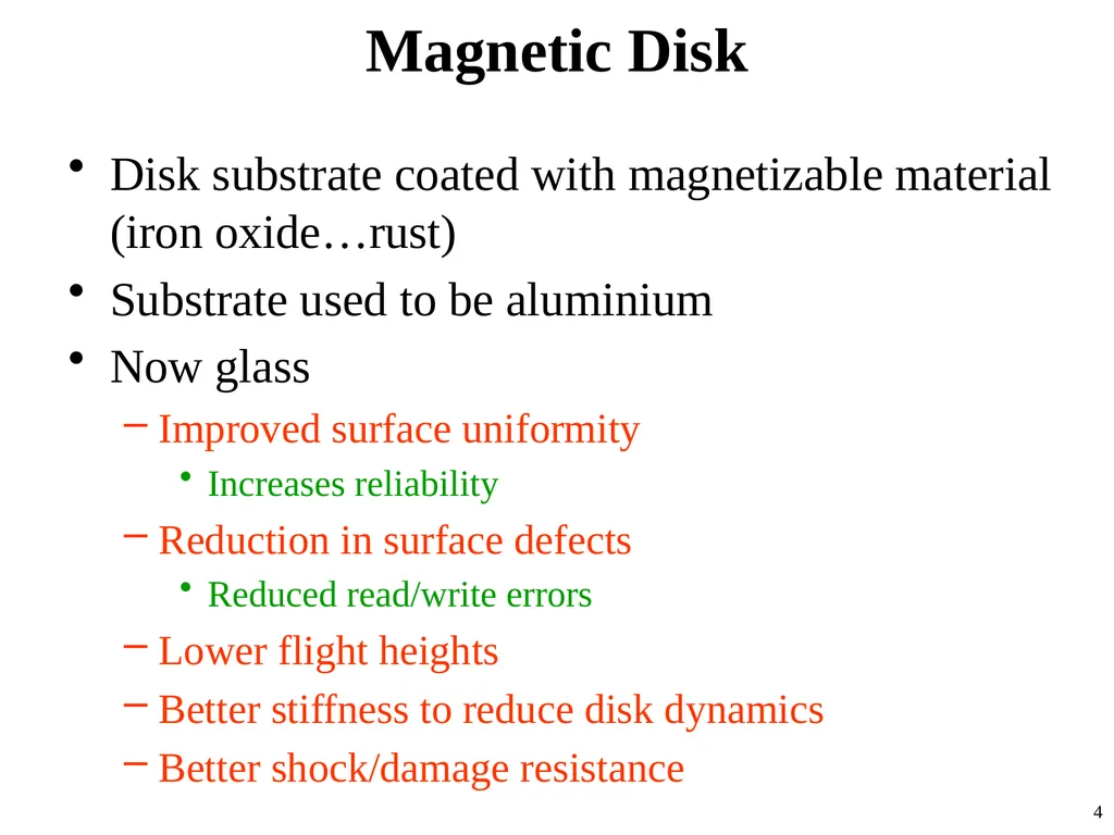
Magnetic Disk Disk substrate coated with magnetizable material (iron oxide…rust)
Substrate used to be aluminium
Now glass
Improved surface uniformity
Increases reliability
Reduction in surface defects
Reduced read/write errors
Lower flight heights
Better stiffness to reduce disk dynamics
Better shock/damage resistance 4<br>
Substrate used to be aluminium
Now glass
Improved surface uniformity
Increases reliability
Reduction in surface defects
Reduced read/write errors
Lower flight heights
Better stiffness to reduce disk dynamics
Better shock/damage resistance 4<br>
05
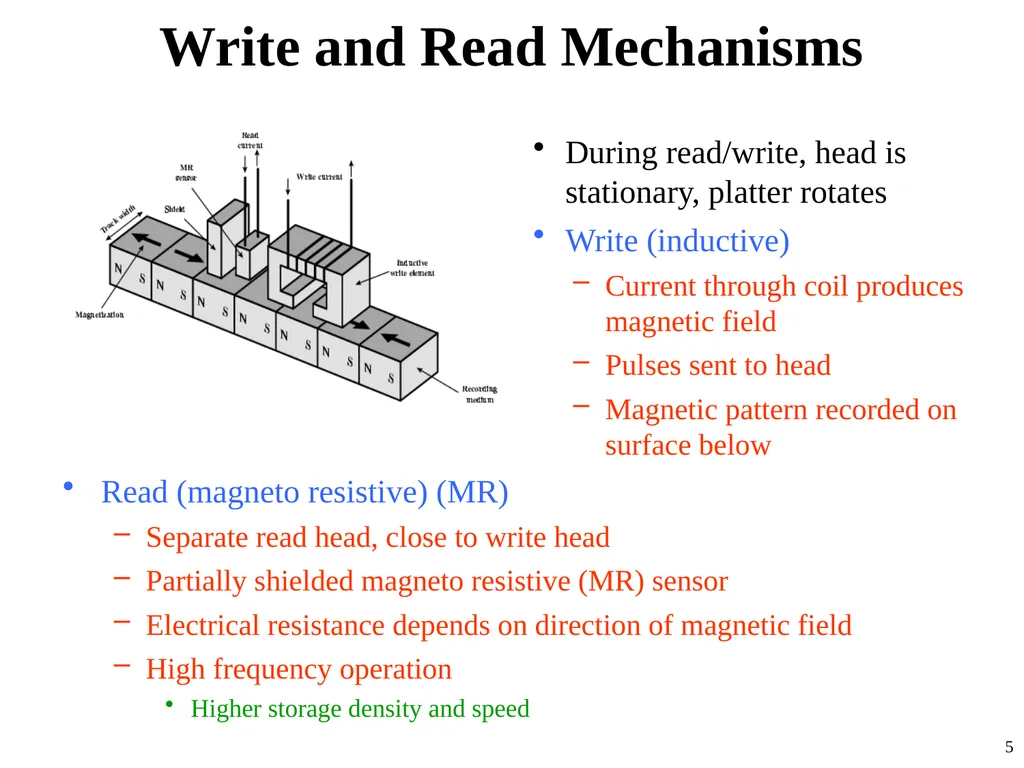
Write and Read Mechanisms During read/write, head is stationary, platter rotates
Write (inductive)
Current through coil produces magnetic field
Pulses sent to head
Magnetic pattern recorded on surface below
Read (magneto resistive) (MR)
Separate read head, close to write head
Partially shielded magneto resistive (MR) sensor
Electrical resistance depends on direction of magnetic field
High frequency operation
Higher storage density and speed 5<br>
Write (inductive)
Current through coil produces magnetic field
Pulses sent to head
Magnetic pattern recorded on surface below
Read (magneto resistive) (MR)
Separate read head, close to write head
Partially shielded magneto resistive (MR) sensor
Electrical resistance depends on direction of magnetic field
High frequency operation
Higher storage density and speed 5<br>
06
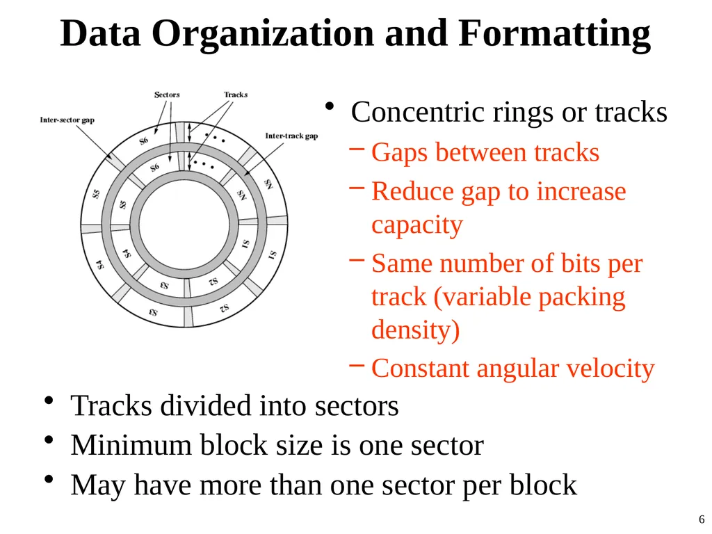
Data Organization and Formatting Concentric rings or tracks
Gaps between tracks
Reduce gap to increase capacity
Same number of bits per track (variable packing density)
Constant angular velocity
Tracks divided into sectors
Minimum block size is one sector
May have more than one sector per block 6<br>
Gaps between tracks
Reduce gap to increase capacity
Same number of bits per track (variable packing density)
Constant angular velocity
Tracks divided into sectors
Minimum block size is one sector
May have more than one sector per block 6<br>
07
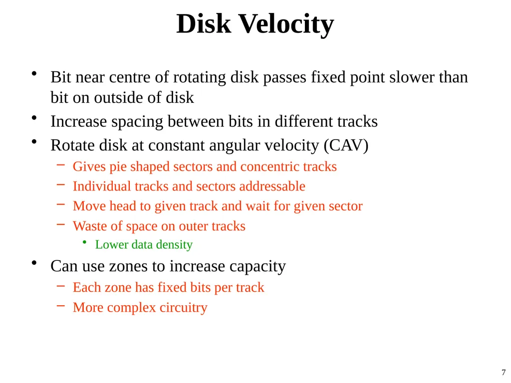
Disk Velocity Bit near centre of rotating disk passes fixed point slower than bit on outside of disk
Increase spacing between bits in different tracks
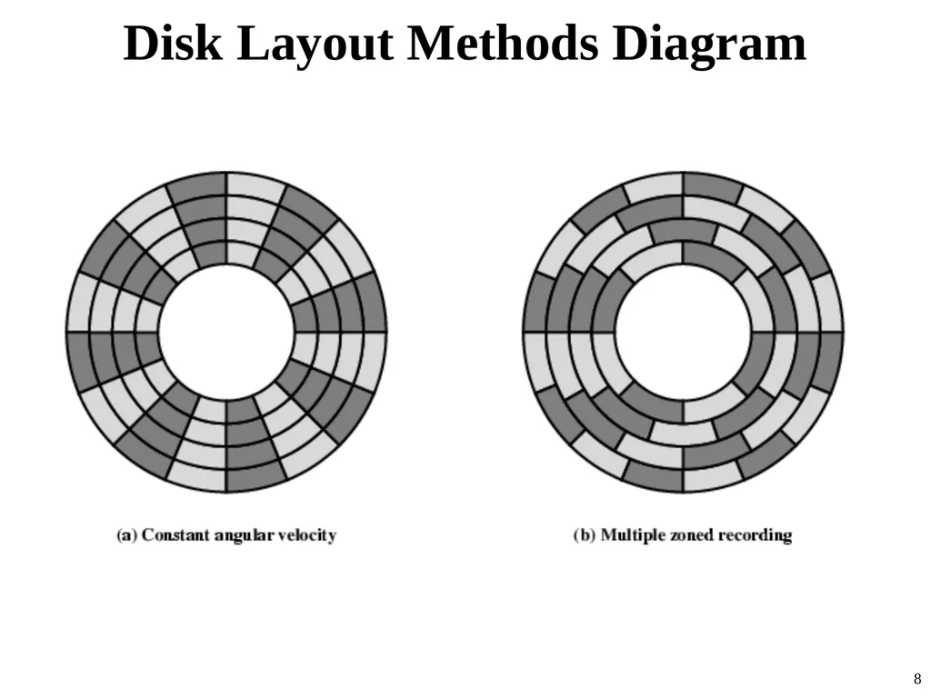
Rotate disk at constant angular velocity (CAV)
Gives pie shaped sectors and concentric tracks
Individual tracks and sectors addressable
Move head to given track and wait for given sector
Waste of space on outer tracks
Lower data density
Can use zones to increase capacity
Each zone has fixed bits per track
More complex circuitry 7<br>
Increase spacing between bits in different tracks
Rotate disk at constant angular velocity (CAV)
Gives pie shaped sectors and concentric tracks
Individual tracks and sectors addressable
Move head to given track and wait for given sector
Waste of space on outer tracks
Lower data density
Can use zones to increase capacity
Each zone has fixed bits per track
More complex circuitry 7<br>
08
Disk Layout Methods Diagram 8<br>
09
Finding Sectors Some means is needed to locate sector positions within a track.
There must be some starting point on the track and a way of identifying the start and end of each sector.
These requirements are handled by means of control data recorded on the disk.
Thus, the disk is formatted with some extra data used only by the disk drive and not accessible to the user. 9<br>
There must be some starting point on the track and a way of identifying the start and end of each sector.
These requirements are handled by means of control data recorded on the disk.
Thus, the disk is formatted with some extra data used only by the disk drive and not accessible to the user. 9<br>
10
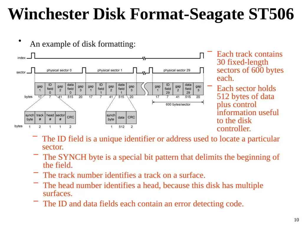
Winchester Disk Format-Seagate ST506 An example of disk formatting:
Each track contains 30 fixed-length sectors of 600 bytes each.
Each sector holds 512 bytes of data plus control information useful to the disk controller.
The ID field is a unique identifier or address used to locate a particular sector.
The SYNCH byte is a special bit pattern that delimits the beginning of the field.
The track number identifies a track on a surface.
The head number identifies a head, because this disk has multiple surfaces.
The ID and data fields each contain an error detecting code. 10<br>
Each track contains 30 fixed-length sectors of 600 bytes each.
Each sector holds 512 bytes of data plus control information useful to the disk controller.
The ID field is a unique identifier or address used to locate a particular sector.
The SYNCH byte is a special bit pattern that delimits the beginning of the field.
The track number identifies a track on a surface.
The head number identifies a head, because this disk has multiple surfaces.
The ID and data fields each contain an error detecting code. 10<br>
11
Characteristics Fixed (rare) or movable head
Removable or fixed
Single or double (usually) sided
Single or multiple platter
Head mechanism
Contact (Floppy)
Fixed gap
Flying (Winchester) 11<br>
Removable or fixed
Single or double (usually) sided
Single or multiple platter
Head mechanism
Contact (Floppy)
Fixed gap
Flying (Winchester) 11<br>
12
Fixed/Movable Head Disk Fixed head
One read write head per track
Heads mounted on fixed ridged arm
Movable head
One read write head per side
Mounted on a movable arm 12<br>
One read write head per track
Heads mounted on fixed ridged arm
Movable head
One read write head per side
Mounted on a movable arm 12<br>
13
Removable or Not Removable disk
Can be removed from drive and replaced with another disk
Provides unlimited storage capacity
Easy data transfer between systems
Nonremovable disk
Permanently mounted in the drive 13<br>
Can be removed from drive and replaced with another disk
Provides unlimited storage capacity
Easy data transfer between systems
Nonremovable disk
Permanently mounted in the drive 13<br>
14
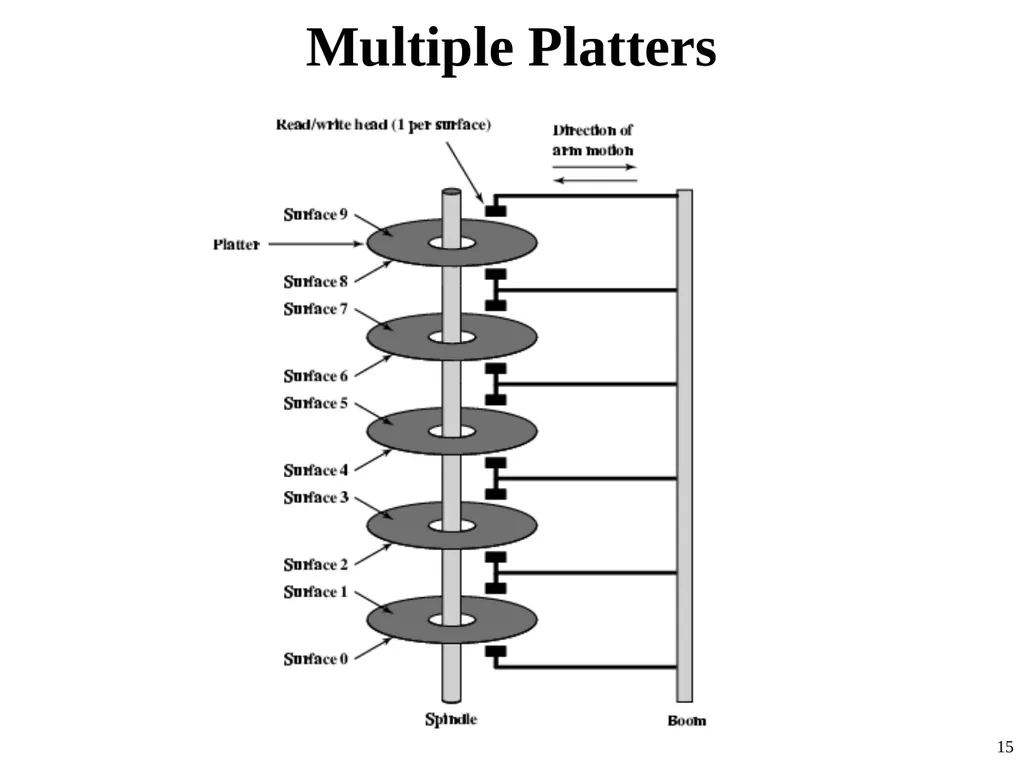
Multiple Platter One head per side
Heads are joined and aligned
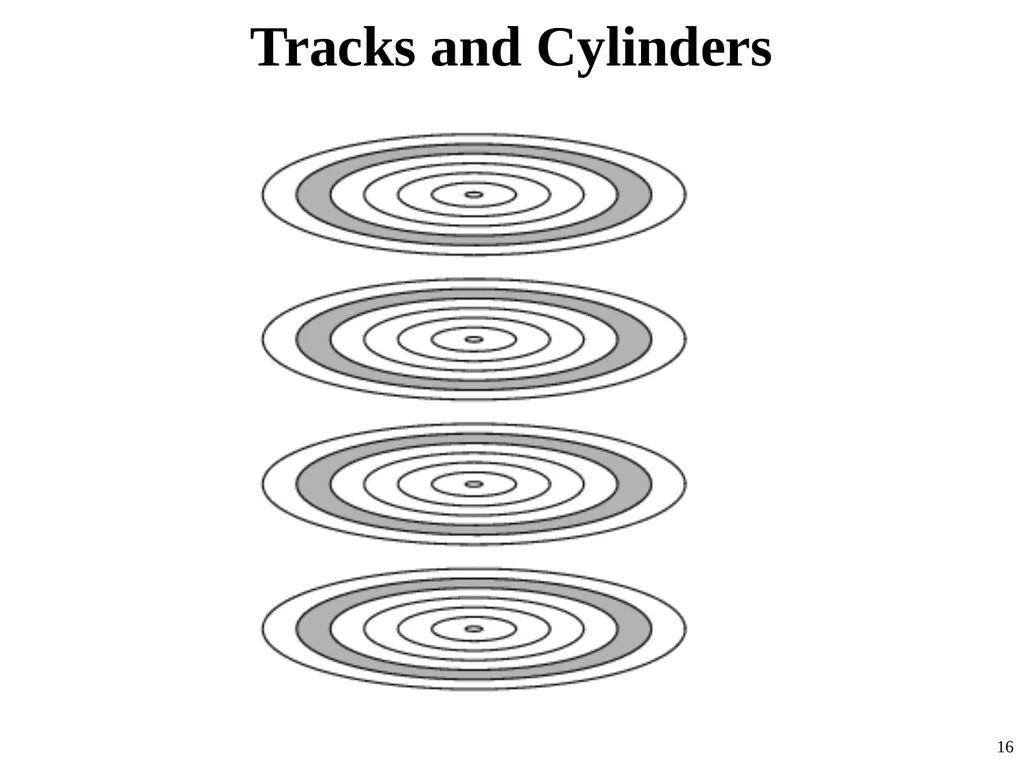
Aligned tracks on each platter form cylinders
Data is striped by cylinder
reduces head movement
Increases speed (transfer rate) 14<br>
Heads are joined and aligned
Aligned tracks on each platter form cylinders
Data is striped by cylinder
reduces head movement
Increases speed (transfer rate) 14<br>
15
Multiple Platters 15<br>
16
Tracks and Cylinders 16<br>
17
Floppy Disk 8”, 5.25”, 3.5”
Small capacity
Up to 1.44Mbyte (2.88M never popular)
Slow
Universal
Cheap
Obsolete? 17<br>
Small capacity
Up to 1.44Mbyte (2.88M never popular)
Slow
Universal
Cheap
Obsolete? 17<br>
18
Winchester Hard Disk (1) Developed by IBM in Winchester (USA)
Sealed unit
One or more platters (disks)
Heads fly on boundary layer of air as disk spins
Very small head to disk gap
Getting more robust
Universal
Cheap
Fastest external storage!
Getting larger all the time
Terabyte now easily available 18<br>
Sealed unit
One or more platters (disks)
Heads fly on boundary layer of air as disk spins
Very small head to disk gap
Getting more robust
Universal
Cheap
Fastest external storage!
Getting larger all the time
Terabyte now easily available 18<br>
19
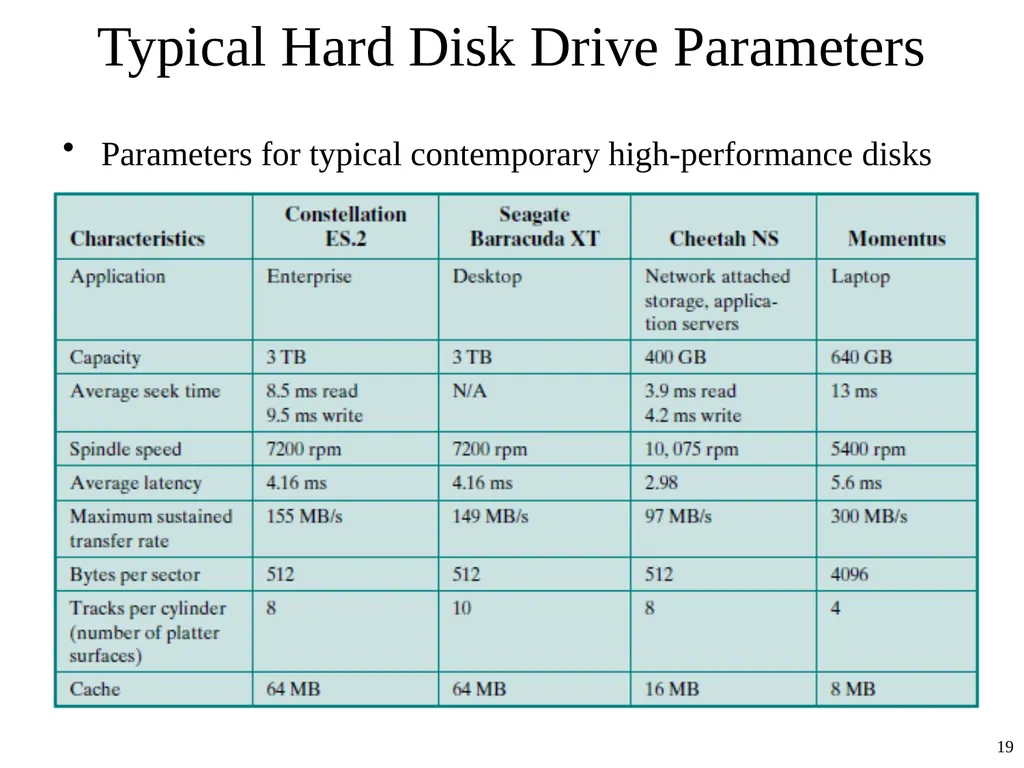
Typical Hard Disk Drive Parameters Parameters for typical contemporary high-performance disks 19<br>
20
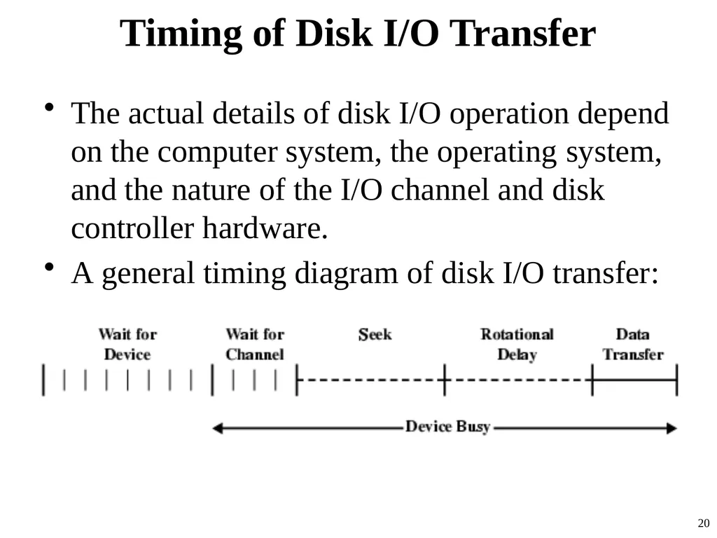
Timing of Disk I/O Transfer The actual details of disk I/O operation depend on the computer system, the operating system, and the nature of the I/O channel and disk controller hardware.
A general timing diagram of disk I/O transfer: 20<br>
A general timing diagram of disk I/O transfer: 20<br>
21
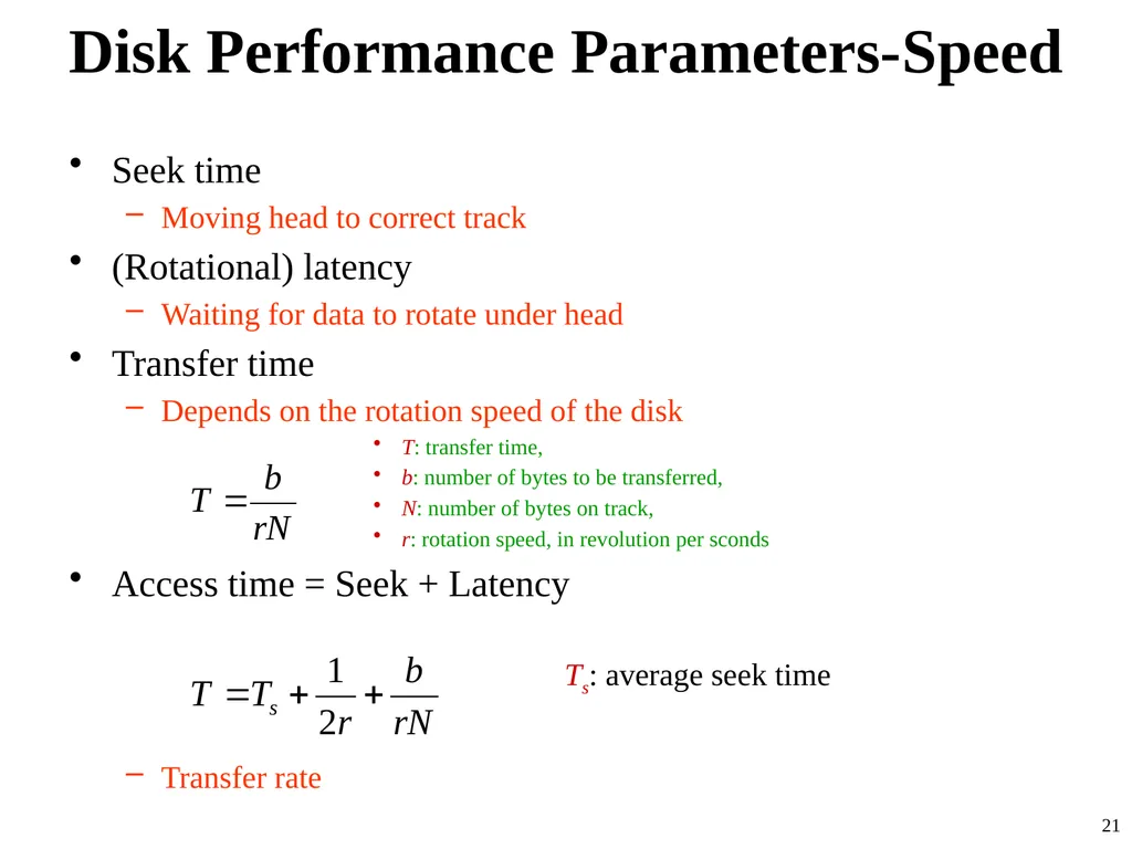
Disk Performance Parameters-Speed Seek time
Moving head to correct track
(Rotational) latency
Waiting for data to rotate under head
Transfer time
Depends on the rotation speed of the disk
T: transfer time,
b: number of bytes to be transferred,
N: number of bytes on track,
r: rotation speed, in revolution per sconds
Access time = Seek + Latency
Ts: average seek time
Transfer rate 21<br>
Moving head to correct track
(Rotational) latency
Waiting for data to rotate under head
Transfer time
Depends on the rotation speed of the disk
T: transfer time,
b: number of bytes to be transferred,
N: number of bytes on track,
r: rotation speed, in revolution per sconds
Access time = Seek + Latency
Ts: average seek time
Transfer rate 21<br>
22
RAID Redundant Array of Independent Disks
Redundant Array of Inexpensive Disks
6 levels in common use
Not a hierarchy
Set of physical disks viewed as single logical drive by O/S
Data distributed across physical drives
Can use redundant capacity to store parity information 22<br>
Redundant Array of Inexpensive Disks
6 levels in common use
Not a hierarchy
Set of physical disks viewed as single logical drive by O/S
Data distributed across physical drives
Can use redundant capacity to store parity information 22<br>
23
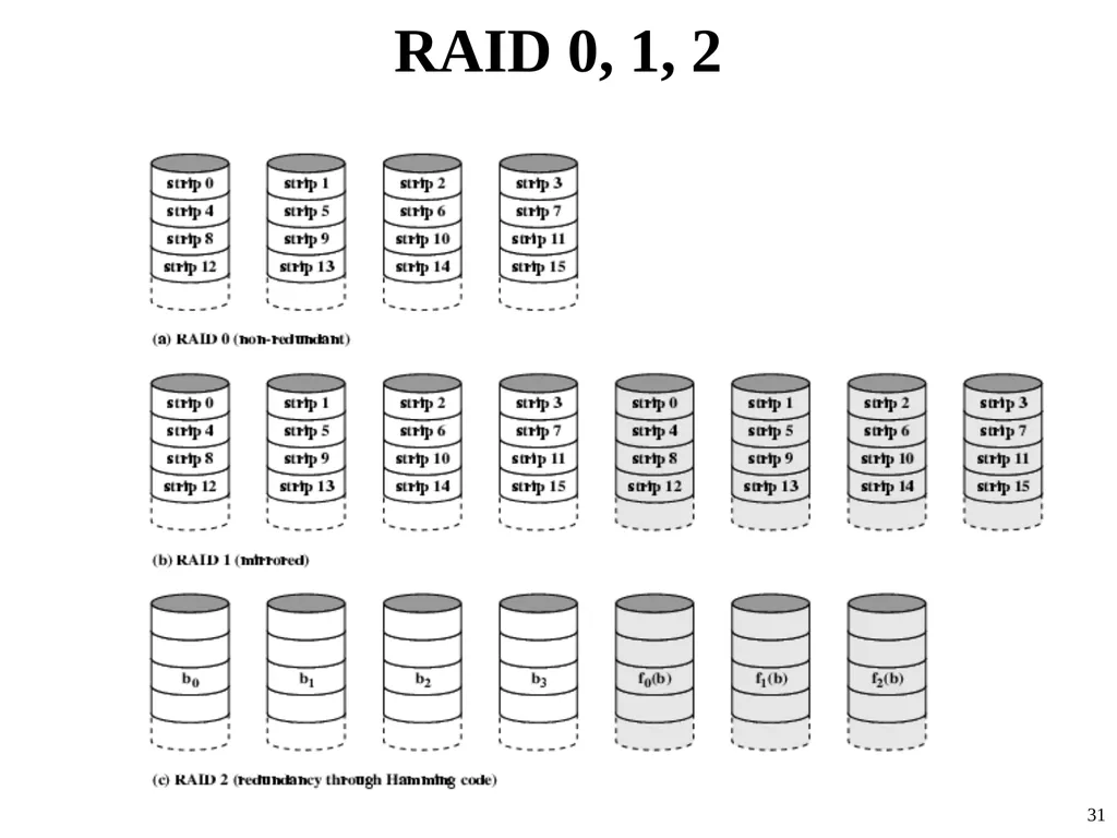
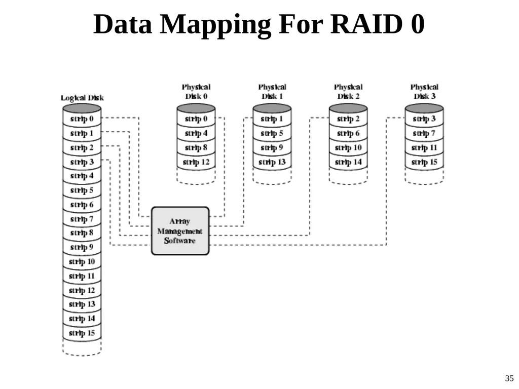
RAID 0 No redundancy
Data striped across all disks
Round Robin striping
Increase speed
Multiple data requests probably not on same disk
Disks seek in parallel
A set of data is likely to be striped across multiple disks 23<br>
Data striped across all disks
Round Robin striping
Increase speed
Multiple data requests probably not on same disk
Disks seek in parallel
A set of data is likely to be striped across multiple disks 23<br>
24
RAID 1 Mirrored Disks
Data is striped across disks
2 copies of each stripe on separate disks
Read from either
Write to both
Recovery is simple
Swap faulty disk & re-mirror
No down time
Expensive 24<br>
Data is striped across disks
2 copies of each stripe on separate disks
Read from either
Write to both
Recovery is simple
Swap faulty disk & re-mirror
No down time
Expensive 24<br>
25
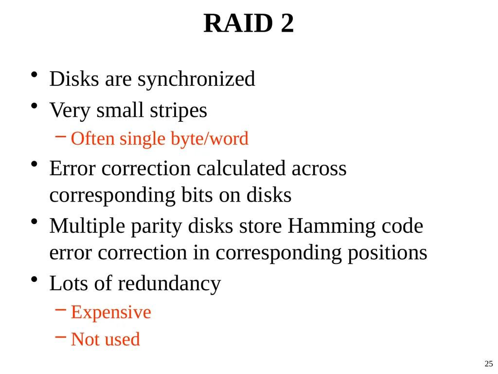
RAID 2 Disks are synchronized
Very small stripes
Often single byte/word
Error correction calculated across corresponding bits on disks
Multiple parity disks store Hamming code error correction in corresponding positions
Lots of redundancy
Expensive
Not used 25<br>
Very small stripes
Often single byte/word
Error correction calculated across corresponding bits on disks
Multiple parity disks store Hamming code error correction in corresponding positions
Lots of redundancy
Expensive
Not used 25<br>
26
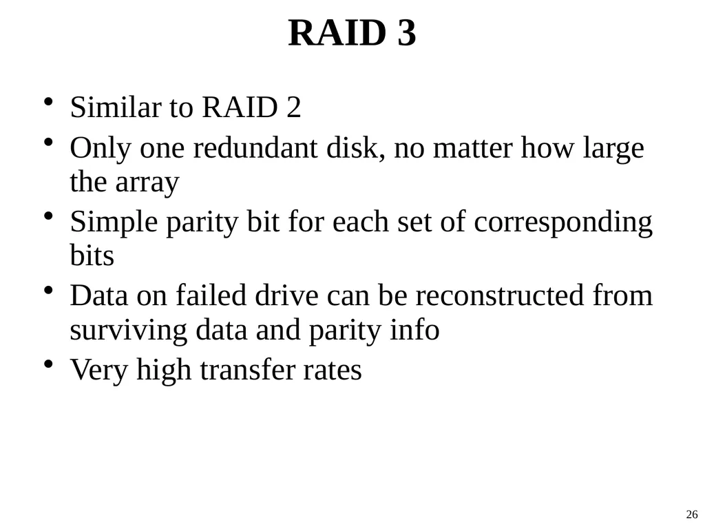
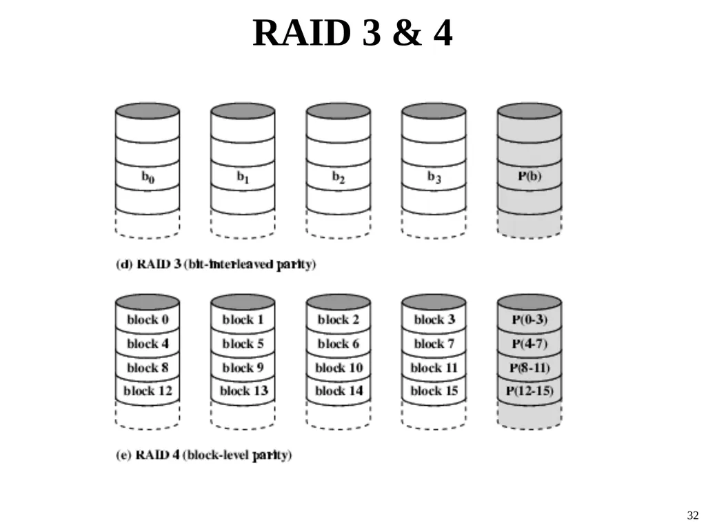
RAID 3 Similar to RAID 2
Only one redundant disk, no matter how large the array
Simple parity bit for each set of corresponding bits
Data on failed drive can be reconstructed from surviving data and parity info
Very high transfer rates 26<br>
Only one redundant disk, no matter how large the array
Simple parity bit for each set of corresponding bits
Data on failed drive can be reconstructed from surviving data and parity info
Very high transfer rates 26<br>
27
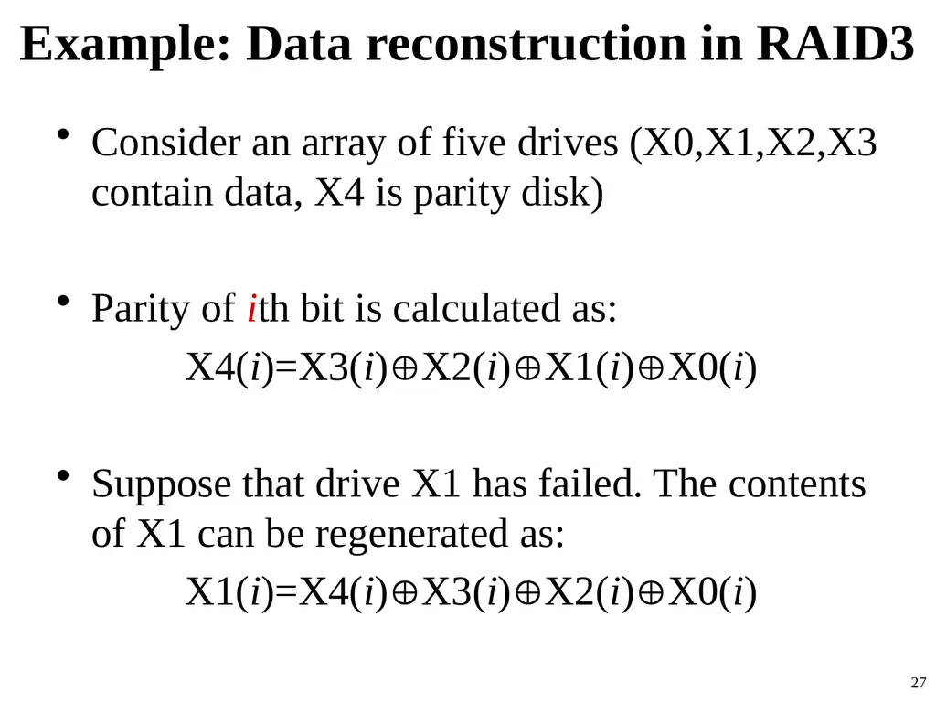
Example: Data reconstruction in RAID3 Consider an array of five drives (X0,X1,X2,X3 contain data, X4 is parity disk)
Parity of ith bit is calculated as:
X4(i)=X3(i)X2(i)X1(i)X0(i)
Suppose that drive X1 has failed. The contents of X1 can be regenerated as:
X1(i)=X4(i)X3(i)X2(i)X0(i) 27<br>
Parity of ith bit is calculated as:
X4(i)=X3(i)X2(i)X1(i)X0(i)
Suppose that drive X1 has failed. The contents of X1 can be regenerated as:
X1(i)=X4(i)X3(i)X2(i)X0(i) 27<br>
28
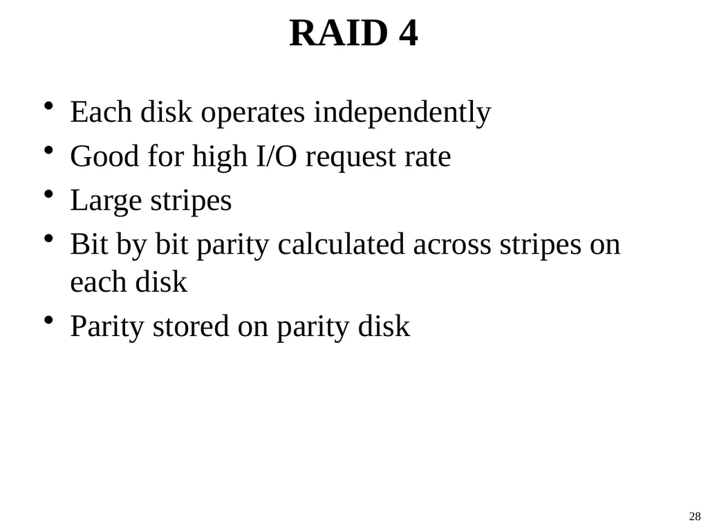
RAID 4 Each disk operates independently
Good for high I/O request rate
Large stripes
Bit by bit parity calculated across stripes on each disk
Parity stored on parity disk 28<br>
Good for high I/O request rate
Large stripes
Bit by bit parity calculated across stripes on each disk
Parity stored on parity disk 28<br>
29
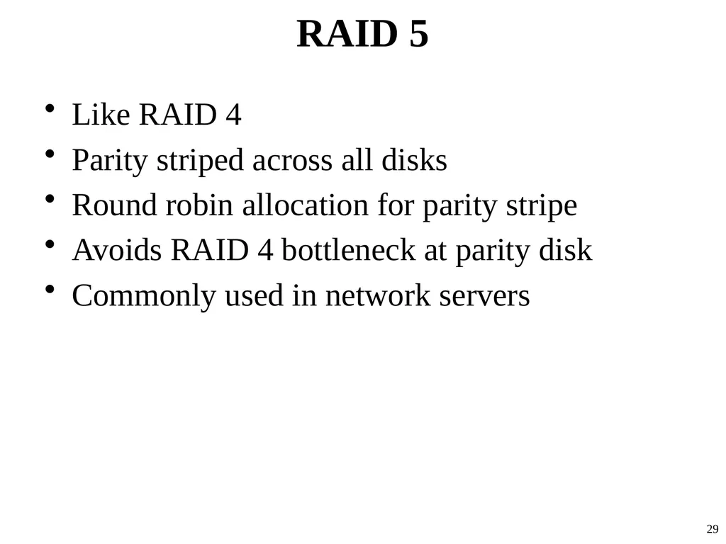
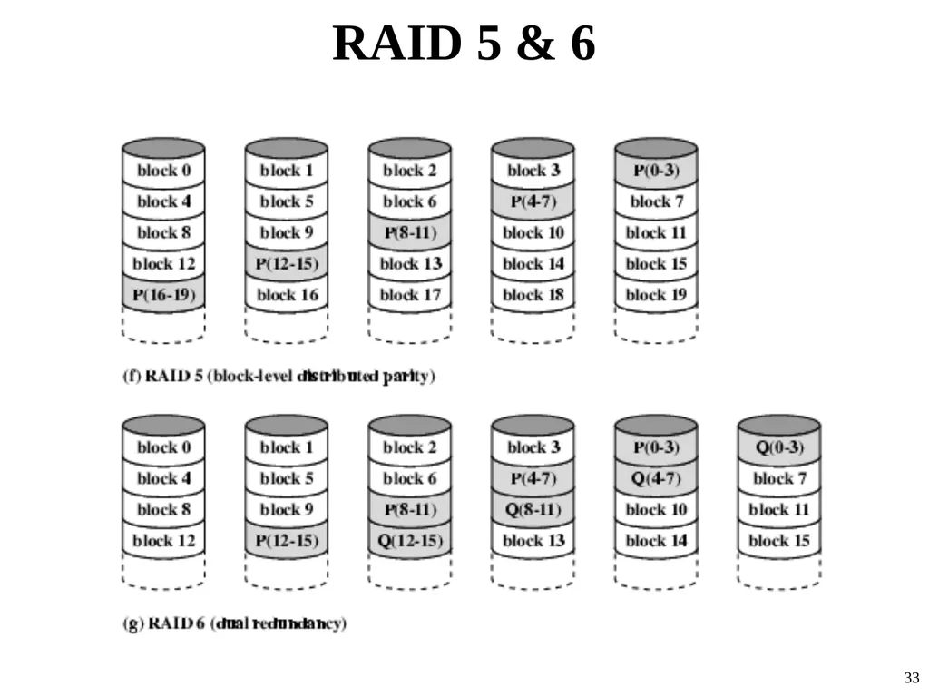
RAID 5 Like RAID 4
Parity striped across all disks
Round robin allocation for parity stripe
Avoids RAID 4 bottleneck at parity disk
Commonly used in network servers 29<br>
Parity striped across all disks
Round robin allocation for parity stripe
Avoids RAID 4 bottleneck at parity disk
Commonly used in network servers 29<br>
30
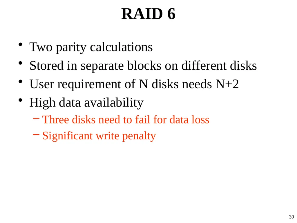
RAID 6 Two parity calculations
Stored in separate blocks on different disks
User requirement of N disks needs N+2
High data availability
Three disks need to fail for data loss
Significant write penalty 30<br>
Stored in separate blocks on different disks
User requirement of N disks needs N+2
High data availability
Three disks need to fail for data loss
Significant write penalty 30<br>
31
RAID 0, 1, 2 31<br>
32
RAID 3 & 4 32<br>
33
RAID 5 & 6 33<br>
34
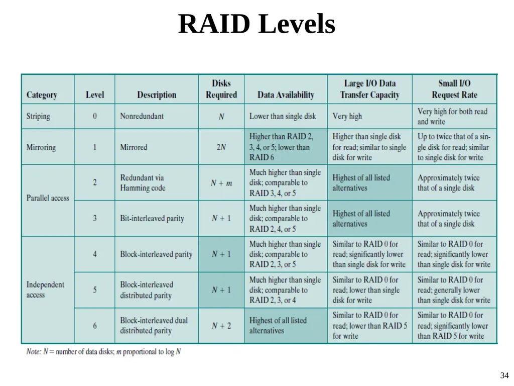
RAID Levels 34<br>
35
Data Mapping For RAID 0 35<br>
36
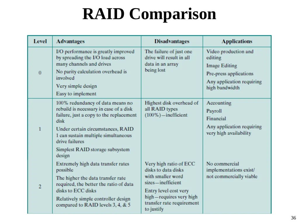
RAID Comparison 36<br>
37
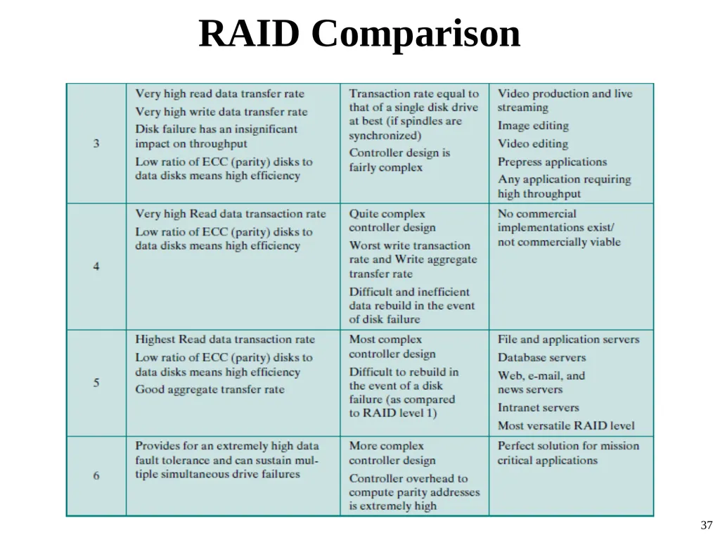
RAID Comparison 37<br>
38
Solid State Drives (SSD) A memory device made with solid state components that can be used as a replacement to a hard disk drive.
In recent years, it is used to complement or even replace hard disk drives (HDDs),
both as internal and external secondary memory
SSDs now on the market and coming on line use a type of semiconductor memory referred to as flash memory 38<br>
In recent years, it is used to complement or even replace hard disk drives (HDDs),
both as internal and external secondary memory
SSDs now on the market and coming on line use a type of semiconductor memory referred to as flash memory 38<br>
39
Flash Memory a type of semiconductor memory that has been around for a number of years
is used in many consumer electronic products,
smart phones, GPS devices, MP3 players, digital cameras, and USB devices.
In recent years, the cost and performance of flash memory has evolved to the point where it is feasible to use flash memory drives to replace HDDs.
Next slide illustrates the basic operation of a flash memory 39<br>
is used in many consumer electronic products,
smart phones, GPS devices, MP3 players, digital cameras, and USB devices.
In recent years, the cost and performance of flash memory has evolved to the point where it is feasible to use flash memory drives to replace HDDs.
Next slide illustrates the basic operation of a flash memory 39<br>
40
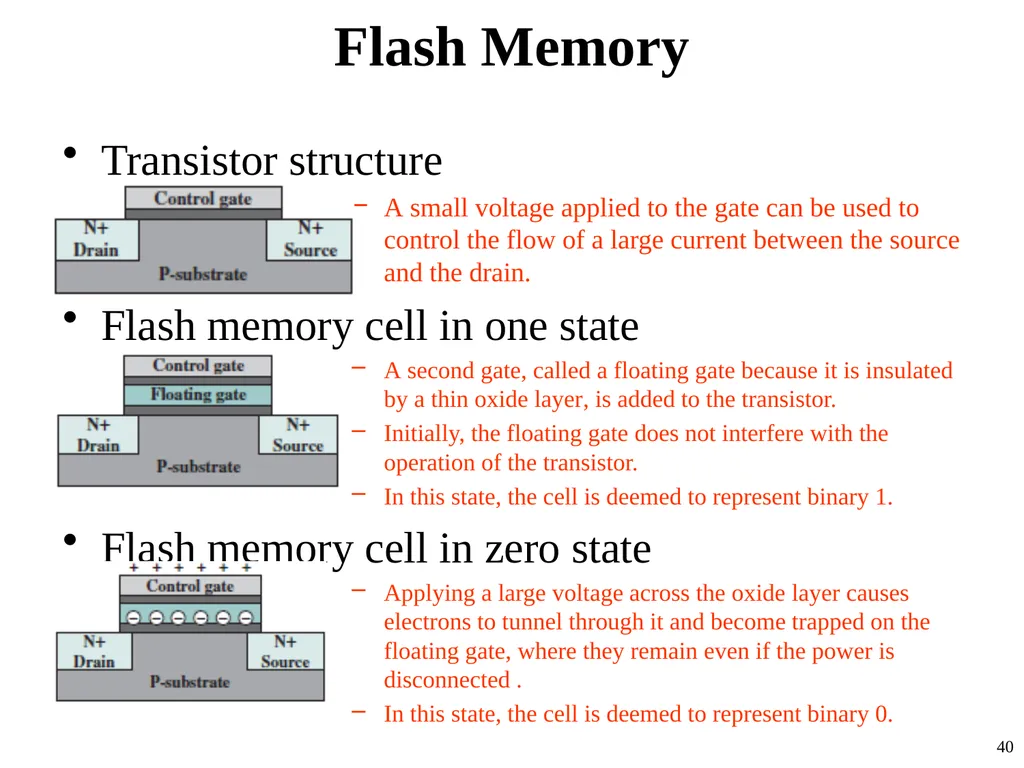
Flash Memory Transistor structure
A small voltage applied to the gate can be used to control the flow of a large current between the source and the drain.
Flash memory cell in one state
A second gate, called a floating gate because it is insulated by a thin oxide layer, is added to the transistor.
Initially, the floating gate does not interfere with the operation of the transistor.
In this state, the cell is deemed to represent binary 1.
Flash memory cell in zero state
Applying a large voltage across the oxide layer causes electrons to tunnel through it and become trapped on the floating gate, where they remain even if the power is disconnected .
In this state, the cell is deemed to represent binary 0. 40<br>
A small voltage applied to the gate can be used to control the flow of a large current between the source and the drain.
Flash memory cell in one state
A second gate, called a floating gate because it is insulated by a thin oxide layer, is added to the transistor.
Initially, the floating gate does not interfere with the operation of the transistor.
In this state, the cell is deemed to represent binary 1.
Flash memory cell in zero state
Applying a large voltage across the oxide layer causes electrons to tunnel through it and become trapped on the floating gate, where they remain even if the power is disconnected .
In this state, the cell is deemed to represent binary 0. 40<br>
41
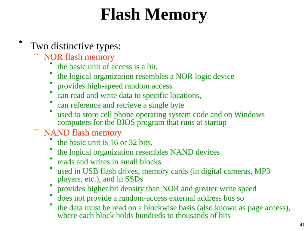
Flash Memory Two distinctive types:
NOR flash memory
the basic unit of access is a bit,
the logical organization resembles a NOR logic device
provides high-speed random access
can read and write data to specific locations,
can reference and retrieve a single byte
used to store cell phone operating system code and on Windows computers for the BIOS program that runs at startup
NAND flash memory
the basic unit is 16 or 32 bits,
the logical organization resembles NAND devices
reads and writes in small blocks
used in USB flash drives, memory cards (in digital cameras, MP3 players, etc.), and in SSDs
provides higher bit density than NOR and greater write speed
does not provide a random-access external address bus so
the data must be read on a blockwise basis (also known as page access), where each block holds hundreds to thousands of bits 41<br>
NOR flash memory
the basic unit of access is a bit,
the logical organization resembles a NOR logic device
provides high-speed random access
can read and write data to specific locations,
can reference and retrieve a single byte
used to store cell phone operating system code and on Windows computers for the BIOS program that runs at startup
NAND flash memory
the basic unit is 16 or 32 bits,
the logical organization resembles NAND devices
reads and writes in small blocks
used in USB flash drives, memory cards (in digital cameras, MP3 players, etc.), and in SSDs
provides higher bit density than NOR and greater write speed
does not provide a random-access external address bus so
the data must be read on a blockwise basis (also known as page access), where each block holds hundreds to thousands of bits 41<br>
42
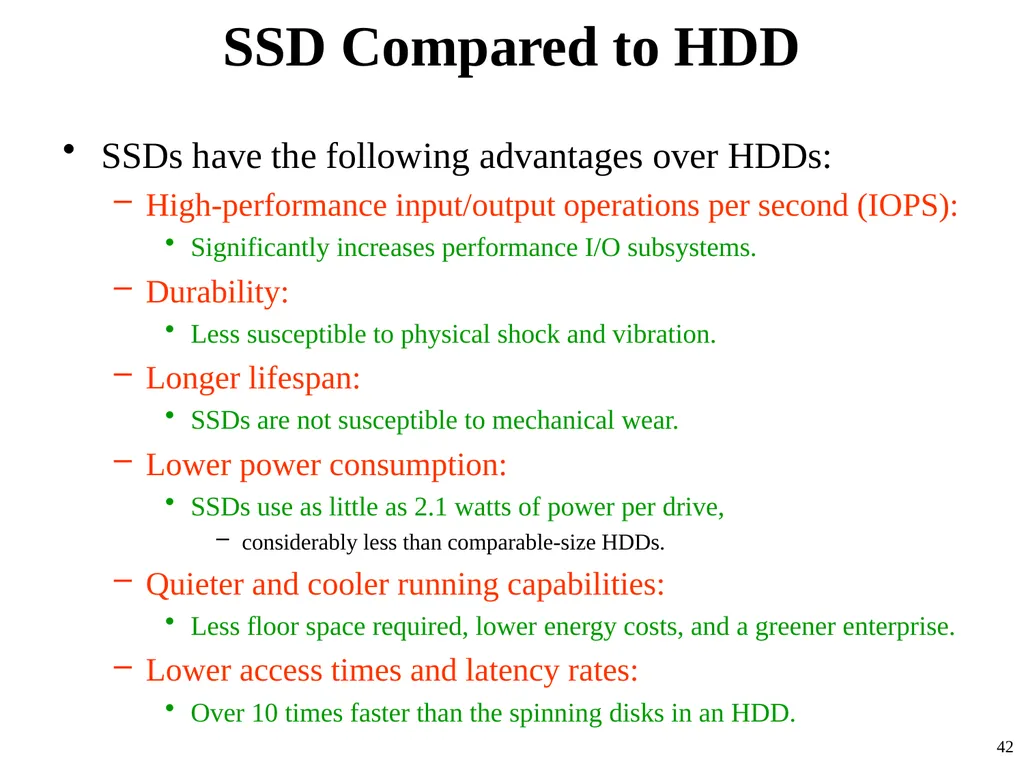
SSD Compared to HDD SSDs have the following advantages over HDDs:
High-performance input/output operations per second (IOPS):
Significantly increases performance I/O subsystems.
Durability:
Less susceptible to physical shock and vibration.
Longer lifespan:
SSDs are not susceptible to mechanical wear.
Lower power consumption:
SSDs use as little as 2.1 watts of power per drive,
considerably less than comparable-size HDDs.
Quieter and cooler running capabilities:
Less floor space required, lower energy costs, and a greener enterprise.
Lower access times and latency rates:
Over 10 times faster than the spinning disks in an HDD. 42<br>
High-performance input/output operations per second (IOPS):
Significantly increases performance I/O subsystems.
Durability:
Less susceptible to physical shock and vibration.
Longer lifespan:
SSDs are not susceptible to mechanical wear.
Lower power consumption:
SSDs use as little as 2.1 watts of power per drive,
considerably less than comparable-size HDDs.
Quieter and cooler running capabilities:
Less floor space required, lower energy costs, and a greener enterprise.
Lower access times and latency rates:
Over 10 times faster than the spinning disks in an HDD. 42<br>
43
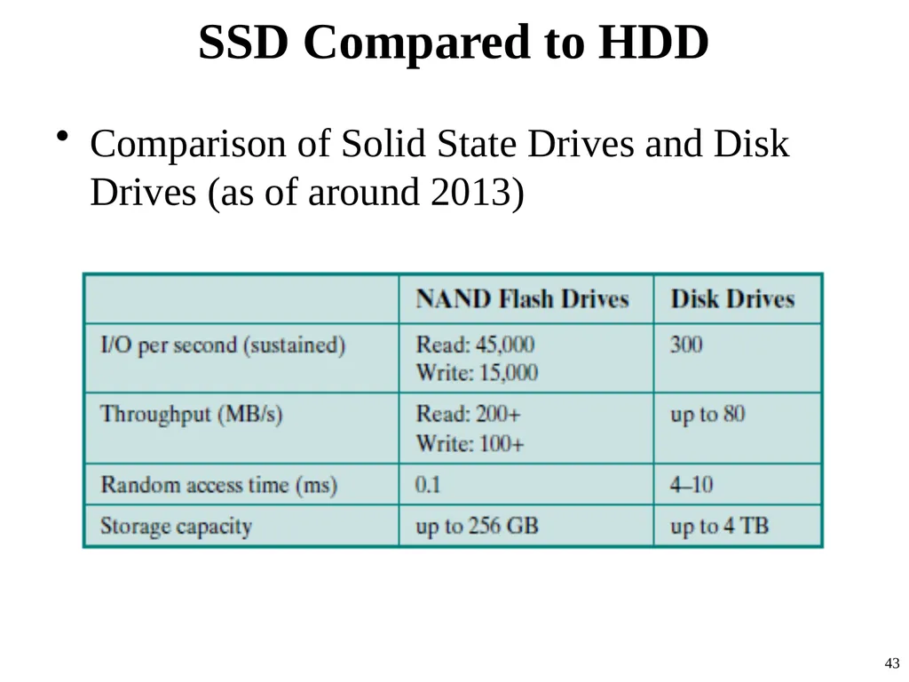
SSD Compared to HDD Comparison of Solid State Drives and Disk Drives (as of around 2013) 43<br>
44
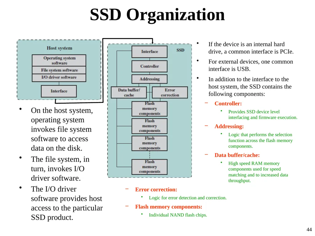
SSD Organization On the host system, operating system invokes file system software to access data on the disk.
The file system, in turn, invokes I/O driver software.
The I/O driver software provides host access to the particular SSD product. 44 If the device is an internal hard drive, a common interface is PCIe.
For external devices, one common interface is USB.
In addition to the interface to the host system, the SSD contains the following components:
Controller:
Provides SSD device level interfacing and firmware execution.
Addressing:
Logic that performs the selection function across the flash memory components.
Data buffer/cache:
High speed RAM memory components used for speed matching and to increased data throughput.
Error correction:
Logic for error detection and correction.
Flash memory components:
Individual NAND flash chips.<br>
The file system, in turn, invokes I/O driver software.
The I/O driver software provides host access to the particular SSD product. 44 If the device is an internal hard drive, a common interface is PCIe.
For external devices, one common interface is USB.
In addition to the interface to the host system, the SSD contains the following components:
Controller:
Provides SSD device level interfacing and firmware execution.
Addressing:
Logic that performs the selection function across the flash memory components.
Data buffer/cache:
High speed RAM memory components used for speed matching and to increased data throughput.
Error correction:
Logic for error detection and correction.
Flash memory components:
Individual NAND flash chips.<br>
45
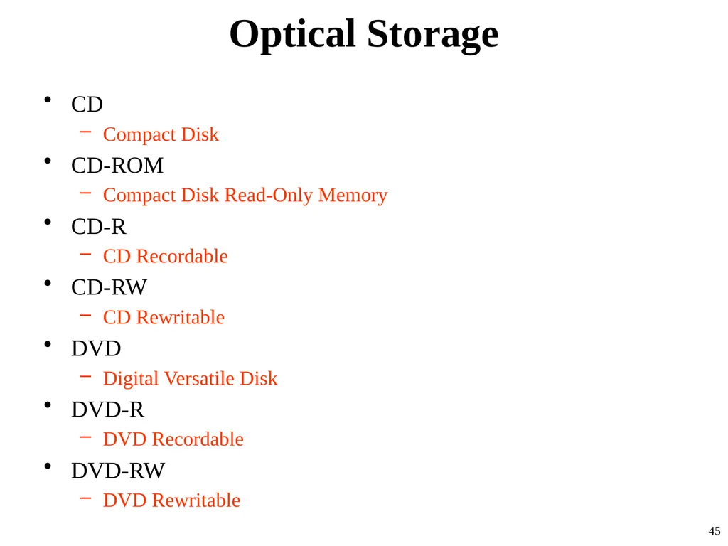
Optical Storage CD
Compact Disk
CD-ROM
Compact Disk Read-Only Memory
CD-R
CD Recordable
CD-RW
CD Rewritable
DVD
Digital Versatile Disk
DVD-R
DVD Recordable
DVD-RW
DVD Rewritable 45<br>
Compact Disk
CD-ROM
Compact Disk Read-Only Memory
CD-R
CD Recordable
CD-RW
CD Rewritable
DVD
Digital Versatile Disk
DVD-R
DVD Recordable
DVD-RW
DVD Rewritable 45<br>
46
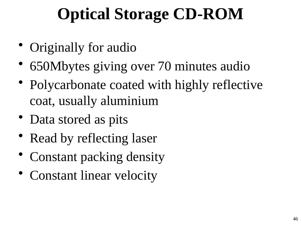
Optical Storage CD-ROM Originally for audio
650Mbytes giving over 70 minutes audio
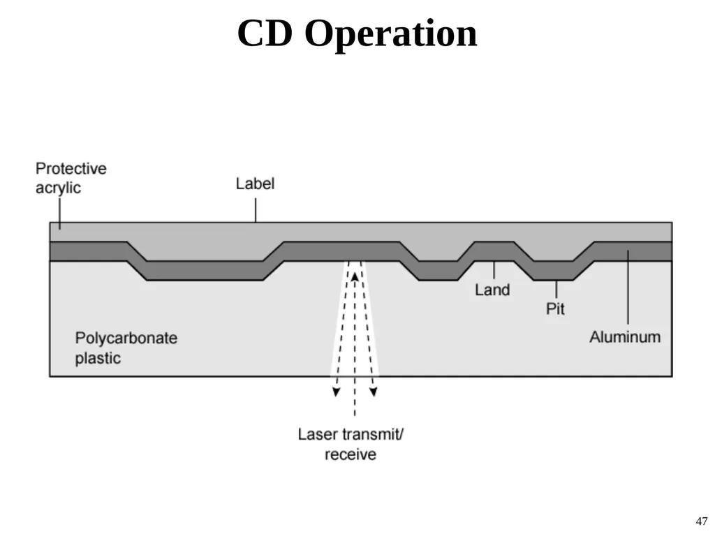
Polycarbonate coated with highly reflective coat, usually aluminium
Data stored as pits
Read by reflecting laser
Constant packing density
Constant linear velocity 46<br>
650Mbytes giving over 70 minutes audio
Polycarbonate coated with highly reflective coat, usually aluminium
Data stored as pits
Read by reflecting laser
Constant packing density
Constant linear velocity 46<br>
47
CD Operation 47<br>
48
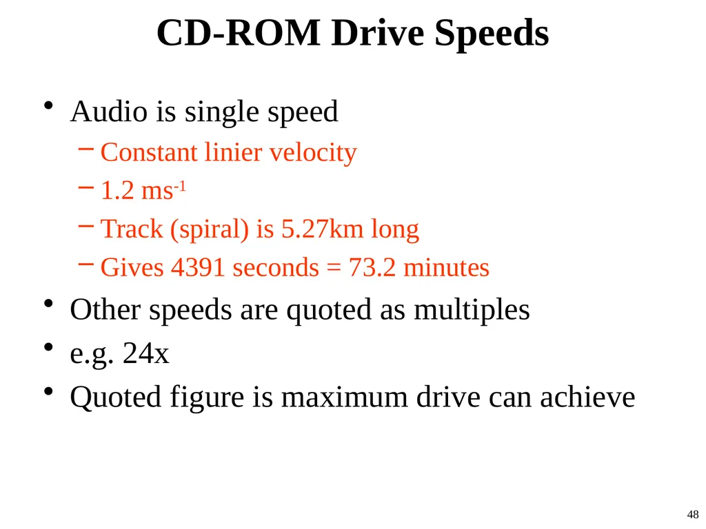
CD-ROM Drive Speeds Audio is single speed
Constant linier velocity
1.2 ms-1
Track (spiral) is 5.27km long
Gives 4391 seconds = 73.2 minutes
Other speeds are quoted as multiples
e.g. 24x
Quoted figure is maximum drive can achieve 48<br>
Constant linier velocity
1.2 ms-1
Track (spiral) is 5.27km long
Gives 4391 seconds = 73.2 minutes
Other speeds are quoted as multiples
e.g. 24x
Quoted figure is maximum drive can achieve 48<br>
49
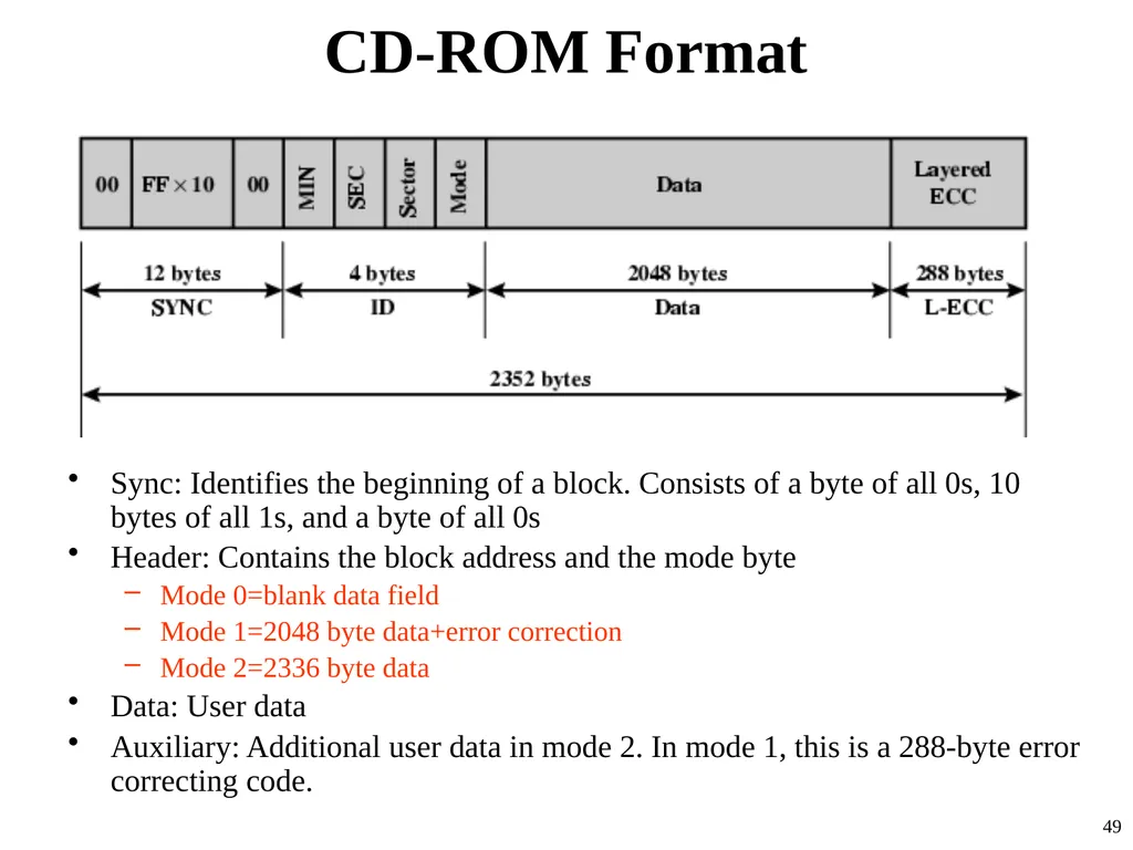
CD-ROM Format Sync: Identifies the beginning of a block. Consists of a byte of all 0s, 10 bytes of all 1s, and a byte of all 0s
Header: Contains the block address and the mode byte
Mode 0=blank data field
Mode 1=2048 byte data+error correction
Mode 2=2336 byte data
Data: User data
Auxiliary: Additional user data in mode 2. In mode 1, this is a 288-byte error correcting code. 49<br>
Header: Contains the block address and the mode byte
Mode 0=blank data field
Mode 1=2048 byte data+error correction
Mode 2=2336 byte data
Data: User data
Auxiliary: Additional user data in mode 2. In mode 1, this is a 288-byte error correcting code. 49<br>
50
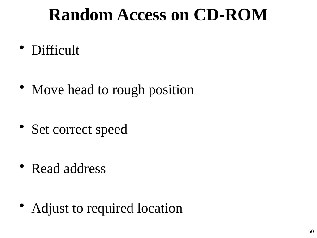
Random Access on CD-ROM Difficult
Move head to rough position
Set correct speed
Read address
Adjust to required location 50<br>
Move head to rough position
Set correct speed
Read address
Adjust to required location 50<br>
51
CD-ROM for & against Large capacity (?)
Easy to mass produce
Removable
Robust
Expensive for small runs
Slow
Read only 51<br>
Easy to mass produce
Removable
Robust
Expensive for small runs
Slow
Read only 51<br>
52
Other Optical Storage CD-Recordable (CD-R)
WORM
Now affordable
Compatible with CD-ROM drives
CD-RW
Erasable
Getting cheaper
Mostly CD-ROM drive compatible
Phase change
Material has two different reflectivities in different phase states 52<br>
WORM
Now affordable
Compatible with CD-ROM drives
CD-RW
Erasable
Getting cheaper
Mostly CD-ROM drive compatible
Phase change
Material has two different reflectivities in different phase states 52<br>
53
DVD Digital Video Disk
Used to indicate a player for movies
Only plays video disks
Digital Versatile Disk
Used to indicate a computer drive
Will read computer disks and play video disks 53<br>
Used to indicate a player for movies
Only plays video disks
Digital Versatile Disk
Used to indicate a computer drive
Will read computer disks and play video disks 53<br>
54
DVD - technology Multi-layer
Very high capacity (4.7G per layer)
Full length movie on single disk
Using MPEG compression
Finally standardized
Movies carry regional coding
Players only play correct region films 54<br>
Very high capacity (4.7G per layer)
Full length movie on single disk
Using MPEG compression
Finally standardized
Movies carry regional coding
Players only play correct region films 54<br>
55
DVD – Writable Loads of trouble with standards
First generation DVD drives may not read first generation DVD-W disks
First generation DVD drives may not read CD-RW disks 55<br>
First generation DVD drives may not read first generation DVD-W disks
First generation DVD drives may not read CD-RW disks 55<br>
56
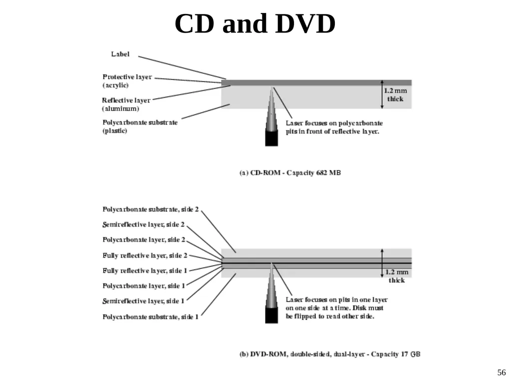
CD and DVD 56<br>
57
Magnetic Tape Serial access
Slow
Very cheap
Backup and archive
Capacity: a couple of 100 GB 57<br>
Slow
Very cheap
Backup and archive
Capacity: a couple of 100 GB 57<br>
58
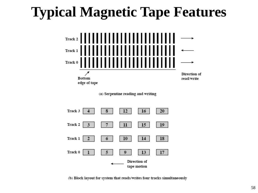
Typical Magnetic Tape Features 58<br>
59
Internet Resources Optical Storage Technology Association
Good source of information about optical storage technology and vendors
Extensive list of relevant links
DLTtape
Good collection of technical information and links to vendors
Search on RAID 59<br>
Good source of information about optical storage technology and vendors
Extensive list of relevant links
DLTtape
Good collection of technical information and links to vendors
Search on RAID 59<br>
60
60<br>