
Computer Modeling of Electronic Circuits with
GB
Published · 30 slides · 0 views
1 / 1
Description
Computer Modeling of Electronic Circuits with LTspice PHYS3360AEP3630 Lecture 2021 1 SPICE Simulation Program with Integrated Circuit Emphasis Originally developed at EE Berkeley Uses mathematical models to describe circuit elements
Related Topics
Share
Embed code
Download this presentation From Below
"Computer Modeling of Electronic Circuits with" is the property of its rightful owner. Permission is granted to download and print the materials on this website for personal, non-commercial use only, and to display it on your personal computer provided you do not modify the materials and that you retain all copyright notices contained in the materials. By downloading content from our website, you accept the terms of this agreement.
Presentation Transcript
01
Computer Modeling of Electronic Circuits with LTspice PHYS3360/AEP3630
Lecture 20/21 1<br>
Lecture 20/21 1<br>
02
SPICE Simulation Program with Integrated Circuit Emphasis Originally developed at EE Berkeley
Uses mathematical models to describe circuit elements
SPICE3 is the latest variant.
- It allows DC and time transient analysis of nonlinear circuits (transistors, diodes, capacitors, etc., also digital circuitry)
- Command line driven interface
- Available in public domain (written in C)
- Has become de-facto the industry standard
- Many spin-offs exist (use modified SPICE2 or SPICE3 as their engine), such as HSPICE, PSPICE, WinSPICE (commercial) 2<br>
Uses mathematical models to describe circuit elements
SPICE3 is the latest variant.
- It allows DC and time transient analysis of nonlinear circuits (transistors, diodes, capacitors, etc., also digital circuitry)
- Command line driven interface
- Available in public domain (written in C)
- Has become de-facto the industry standard
- Many spin-offs exist (use modified SPICE2 or SPICE3 as their engine), such as HSPICE, PSPICE, WinSPICE (commercial) 2<br>
03
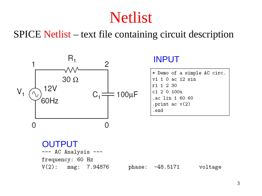
Netlist SPICE Netlist – text file containing circuit description INPUT OUTPUT 3<br>
04
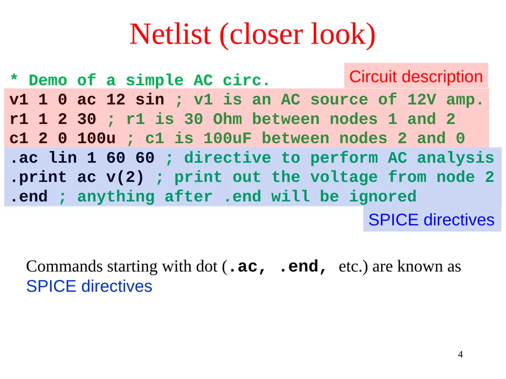
Netlist (closer look) * Demo of a simple AC circ.
v1 1 0 ac 12 sin ; v1 is an AC source of 12V amp.
r1 1 2 30 ; r1 is 30 Ohm between nodes 1 and 2
c1 2 0 100u ; c1 is 100uF between nodes 2 and 0
.ac lin 1 60 60 ; directive to perform AC analysis
.print ac v(2) ; print out the voltage from node 2
.end ; anything after .end will be ignored Commands starting with dot (.ac, .end, etc.) are known as SPICE directives Circuit description SPICE directives 4<br>
v1 1 0 ac 12 sin ; v1 is an AC source of 12V amp.
r1 1 2 30 ; r1 is 30 Ohm between nodes 1 and 2
c1 2 0 100u ; c1 is 100uF between nodes 2 and 0
.ac lin 1 60 60 ; directive to perform AC analysis
.print ac v(2) ; print out the voltage from node 2
.end ; anything after .end will be ignored Commands starting with dot (.ac, .end, etc.) are known as SPICE directives Circuit description SPICE directives 4<br>
05
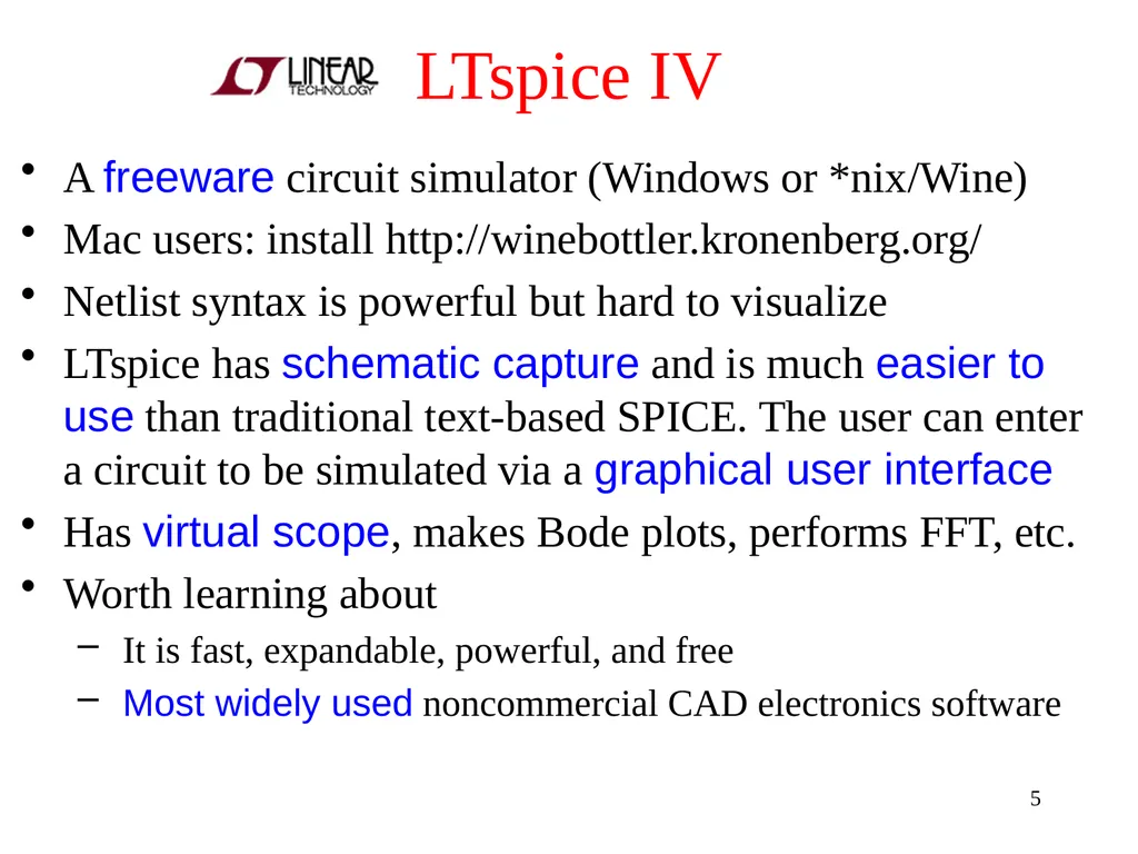
LTspice IV A freeware circuit simulator (Windows or *nix/Wine)
Mac users: install http://winebottler.kronenberg.org/
Netlist syntax is powerful but hard to visualize
LTspice has schematic capture and is much easier to use than traditional text-based SPICE. The user can enter a circuit to be simulated via a graphical user interface
Has virtual scope, makes Bode plots, performs FFT, etc.
Worth learning about
It is fast, expandable, powerful, and free
Most widely used noncommercial CAD electronics software 5<br>
Mac users: install http://winebottler.kronenberg.org/
Netlist syntax is powerful but hard to visualize
LTspice has schematic capture and is much easier to use than traditional text-based SPICE. The user can enter a circuit to be simulated via a graphical user interface
Has virtual scope, makes Bode plots, performs FFT, etc.
Worth learning about
It is fast, expandable, powerful, and free
Most widely used noncommercial CAD electronics software 5<br>
06
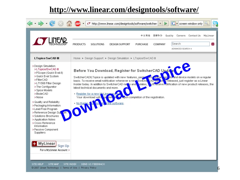
http://www.linear.com/designtools/software/ Download LTspice 6<br>
07
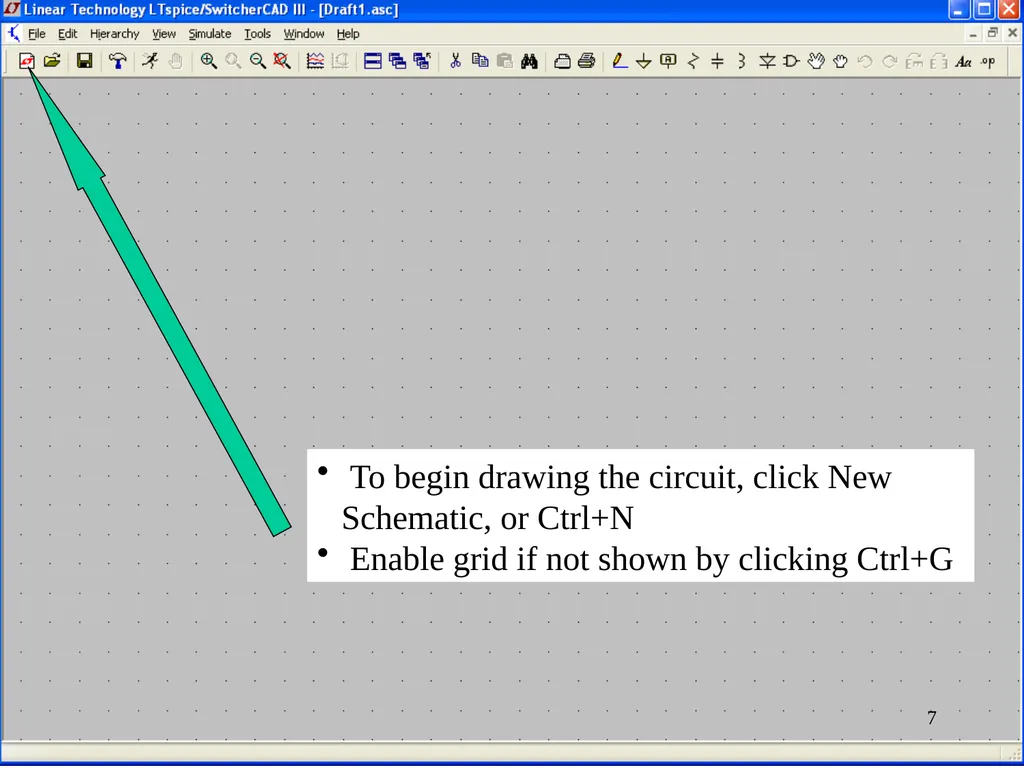
To begin drawing the circuit, click New Schematic, or Ctrl+N
Enable grid if not shown by clicking Ctrl+G 7<br>
Enable grid if not shown by clicking Ctrl+G 7<br>
08
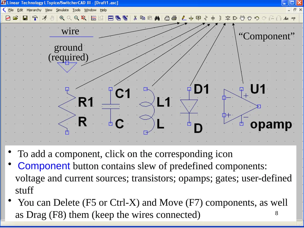
wire ground (required) “Component” To add a component, click on the corresponding icon
Component button contains slew of predefined components: voltage and current sources; transistors; opamps; gates; user-defined stuff
You can Delete (F5 or Ctrl-X) and Move (F7) components, as well as Drag (F8) them (keep the wires connected) 8<br>
Component button contains slew of predefined components: voltage and current sources; transistors; opamps; gates; user-defined stuff
You can Delete (F5 or Ctrl-X) and Move (F7) components, as well as Drag (F8) them (keep the wires connected) 8<br>
09
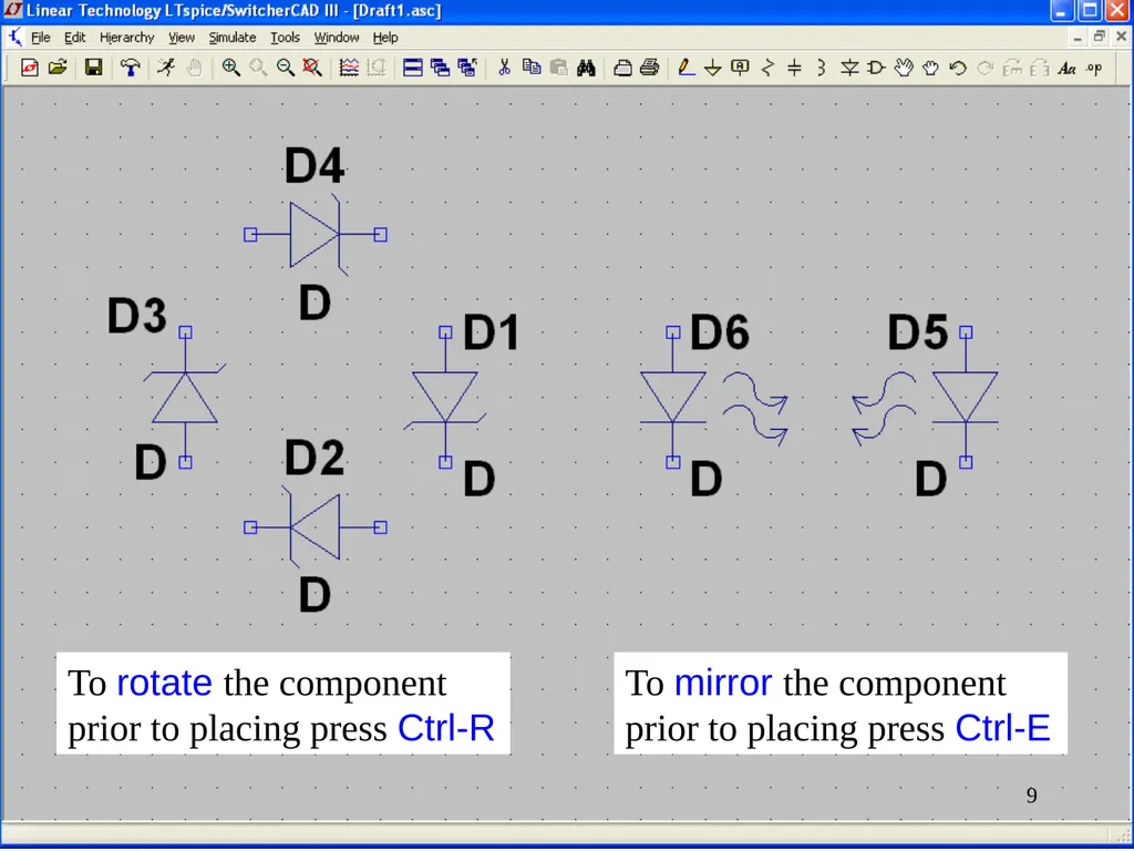
To rotate the component prior to placing press Ctrl-R To mirror the component prior to placing press Ctrl-E 9<br>
10
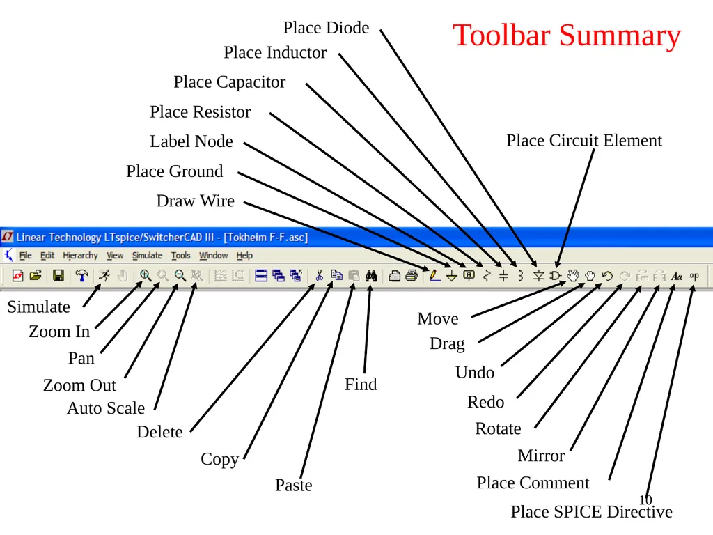
Place Circuit Element Draw Wire Place Ground Label Node Place Resistor Place Capacitor Place Inductor Place Diode Move Drag Undo Redo Rotate Mirror Place Comment Place SPICE Directive Zoom In Pan Zoom Out Auto Scale Delete Copy Paste Find Simulate Toolbar Summary 10<br>
11
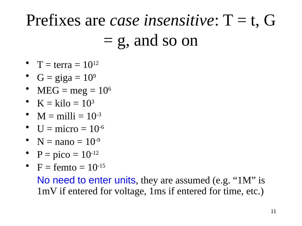
Prefixes are case insensitive: T = t, G = g, and so on T = terra = 1012
G = giga = 109
MEG = meg = 106
K = kilo = 103
M = milli = 10-3
U = micro = 10-6
N = nano = 10-9
P = pico = 10-12
F = femto = 10-15
No need to enter units, they are assumed (e.g. “1M” is 1mV if entered for voltage, 1ms if entered for time, etc.) 11<br>
G = giga = 109
MEG = meg = 106
K = kilo = 103
M = milli = 10-3
U = micro = 10-6
N = nano = 10-9
P = pico = 10-12
F = femto = 10-15
No need to enter units, they are assumed (e.g. “1M” is 1mV if entered for voltage, 1ms if entered for time, etc.) 11<br>
12
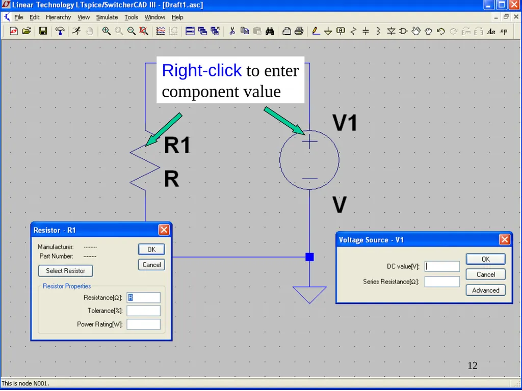
Right-click to enter component value 12<br>
13
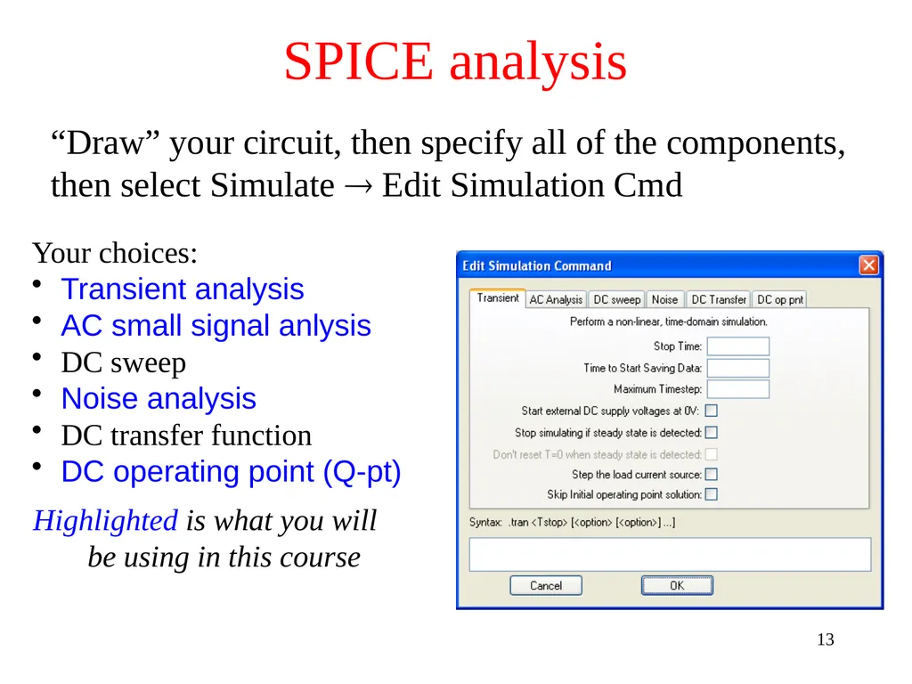
“Draw” your circuit, then specify all of the components, then select Simulate Edit Simulation Cmd Your choices:
Transient analysis
AC small signal anlysis
DC sweep
Noise analysis
DC transfer function
DC operating point (Q-pt)
Highlighted is what you will be using in this course SPICE analysis 13<br>
Transient analysis
AC small signal anlysis
DC sweep
Noise analysis
DC transfer function
DC operating point (Q-pt)
Highlighted is what you will be using in this course SPICE analysis 13<br>
14
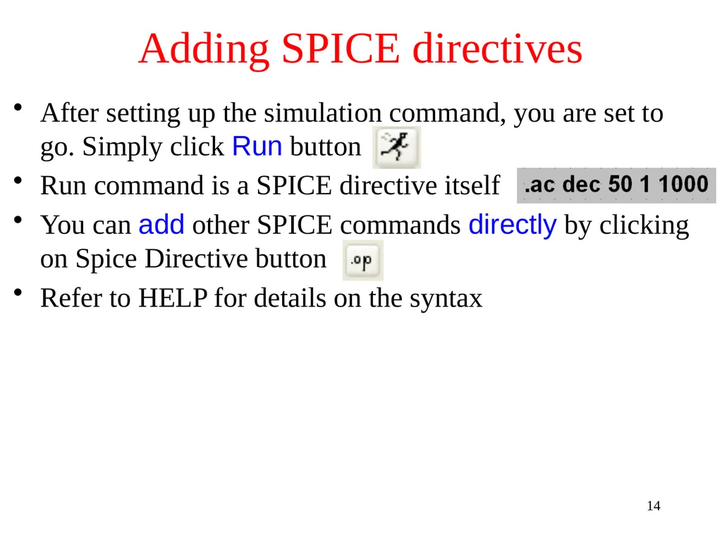
After setting up the simulation command, you are set to go. Simply click Run button
Run command is a SPICE directive itself
You can add other SPICE commands directly by clicking on Spice Directive button
Refer to HELP for details on the syntax Adding SPICE directives 14<br>
Run command is a SPICE directive itself
You can add other SPICE commands directly by clicking on Spice Directive button
Refer to HELP for details on the syntax Adding SPICE directives 14<br>
15
Your home assignment for this week includes working your way through Supplement Part 1 (a tutorial) then working home problems using LTspice.
Install LTspice on your own computer. LTspice is installed on all lab computers and in A&EP computer room
Supplement Part 2 contains LTspice experiments. They will start after the break and are to be done in the same way as the usual lab experiments, but using LTspice. Print out results using the lab printers, attach them to your lab report, etc.
You can do LTspice experiments anywhere you have access to LTspice, not just in the lab SPICE use in this course 15<br>
Install LTspice on your own computer. LTspice is installed on all lab computers and in A&EP computer room
Supplement Part 2 contains LTspice experiments. They will start after the break and are to be done in the same way as the usual lab experiments, but using LTspice. Print out results using the lab printers, attach them to your lab report, etc.
You can do LTspice experiments anywhere you have access to LTspice, not just in the lab SPICE use in this course 15<br>
16
We will look at how to setup two examples
Example1: crossover corrected push-pull amp (ex6.10)
Example2: active filter
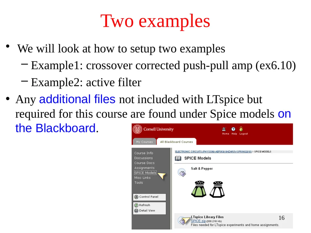
Any additional files not included with LTspice but required for this course are found under Spice models on the Blackboard. Two examples 16<br>
Example1: crossover corrected push-pull amp (ex6.10)
Example2: active filter
Any additional files not included with LTspice but required for this course are found under Spice models on the Blackboard. Two examples 16<br>
17
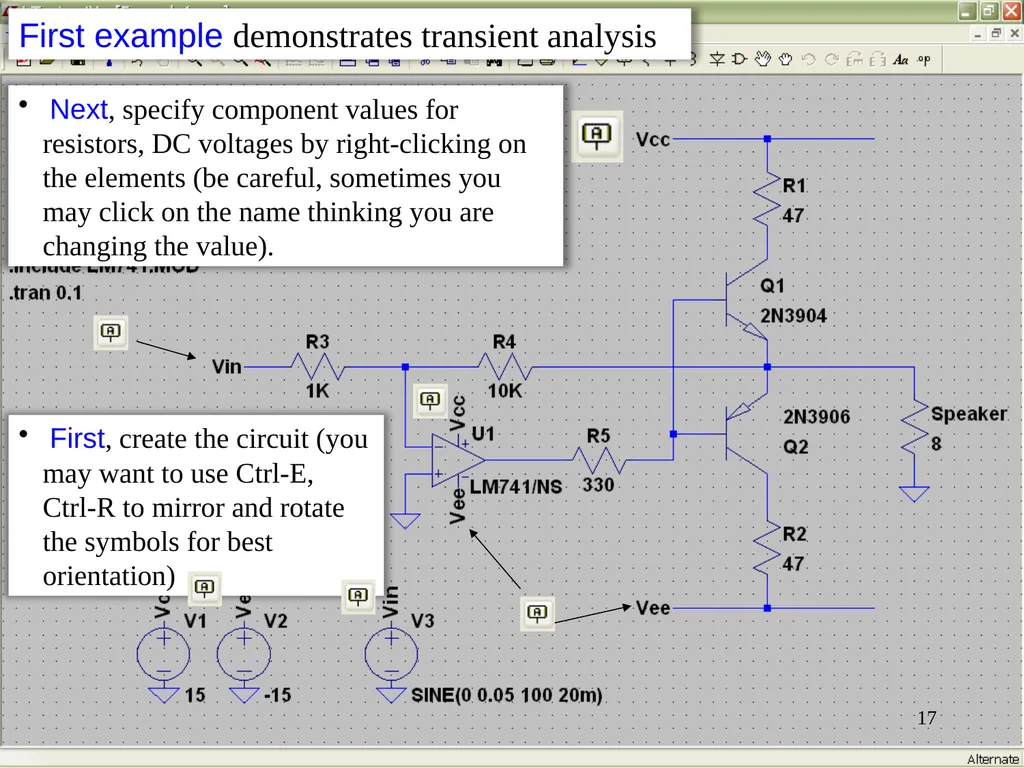
First, create the circuit (you may want to use Ctrl-E, Ctrl-R to mirror and rotate the symbols for best orientation) 17 Next, specify component values for resistors, DC voltages by right-clicking on the elements (be careful, sometimes you may click on the name thinking you are changing the value). First example demonstrates transient analysis<br>
18
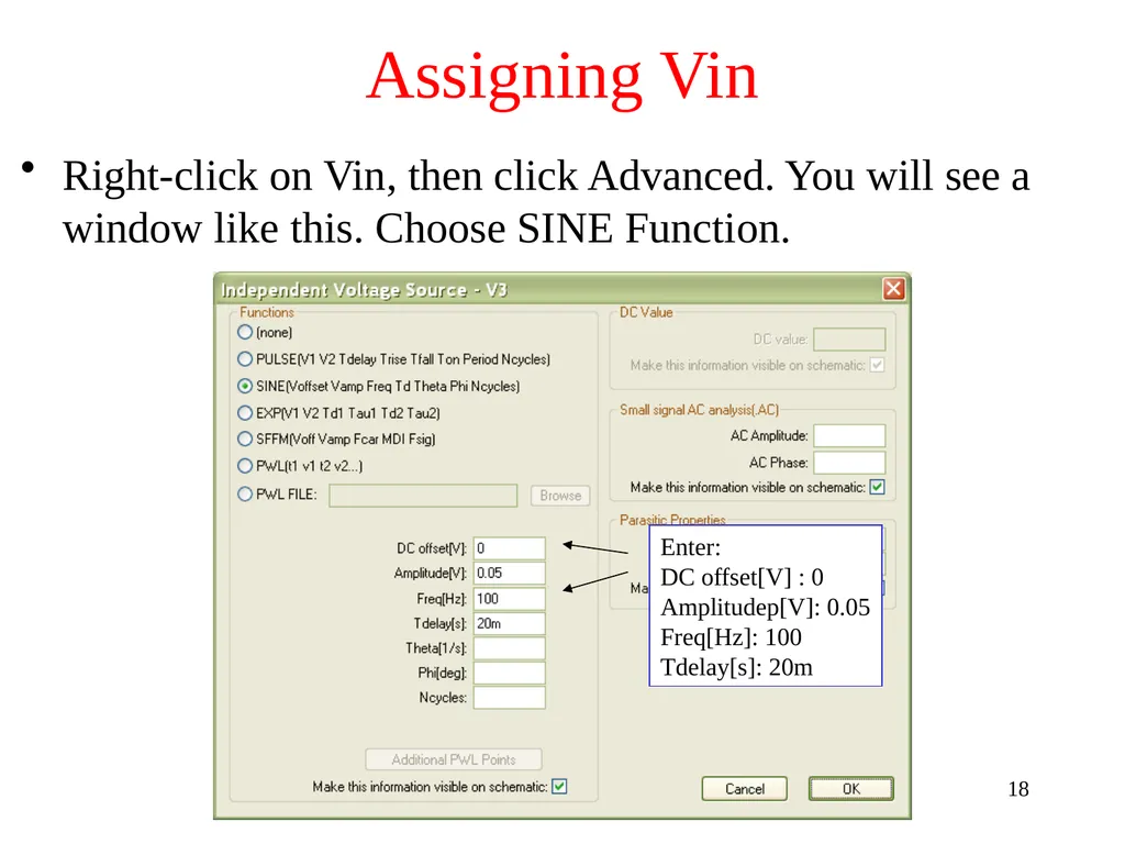
Assigning Vin Right-click on Vin, then click Advanced. You will see a window like this. Choose SINE Function. Enter:
DC offset[V] : 0
Amplitudep[V]: 0.05
Freq[Hz]: 100
Tdelay[s]: 20m 18<br>
DC offset[V] : 0
Amplitudep[V]: 0.05
Freq[Hz]: 100
Tdelay[s]: 20m 18<br>
19
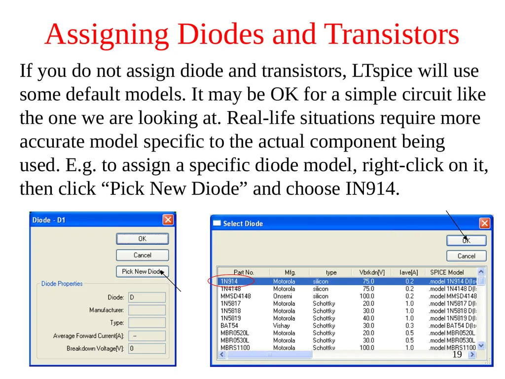
Assigning Diodes and Transistors If you do not assign diode and transistors, LTspice will use some default models. It may be OK for a simple circuit like the one we are looking at. Real-life situations require more accurate model specific to the actual component being used. E.g. to assign a specific diode model, right-click on it, then click “Pick New Diode” and choose IN914. 19<br>
20
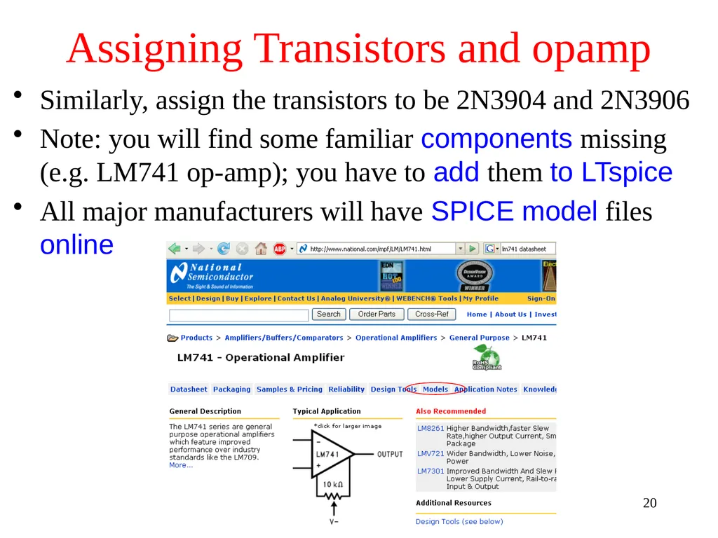
Assigning Transistors and opamp Similarly, assign the transistors to be 2N3904 and 2N3906
Note: you will find some familiar components missing (e.g. LM741 op-amp); you have to add them to LTspice
All major manufacturers will have SPICE model files online 20<br>
Note: you will find some familiar components missing (e.g. LM741 op-amp); you have to add them to LTspice
All major manufacturers will have SPICE model files online 20<br>
21
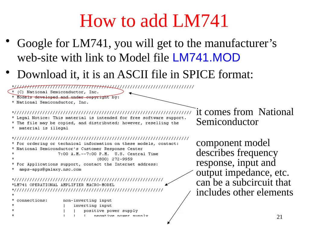
How to add LM741 Google for LM741, you will get to the manufacturer’s web-site with link to Model file LM741.MOD
Download it, it is an ASCII file in SPICE format: it comes from National Semiconductor component model describes frequency response, input and output impedance, etc. can be a subcircuit that includes other elements 21<br>
Download it, it is an ASCII file in SPICE format: it comes from National Semiconductor component model describes frequency response, input and output impedance, etc. can be a subcircuit that includes other elements 21<br>
22
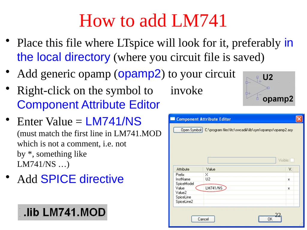
How to add LM741 Place this file where LTspice will look for it, preferably in the local directory (where you circuit file is saved)
Add generic opamp (opamp2) to your circuit
Right-click on the symbol to invoke Component Attribute Editor
Enter Value = LM741/NS (must match the first line in LM741.MOD file, which is not a comment, i.e. not preceded by *, something like .SUBCKT LM741/NS …)
Add SPICE directive 22<br>
Add generic opamp (opamp2) to your circuit
Right-click on the symbol to invoke Component Attribute Editor
Enter Value = LM741/NS (must match the first line in LM741.MOD file, which is not a comment, i.e. not preceded by *, something like .SUBCKT LM741/NS …)
Add SPICE directive 22<br>
23
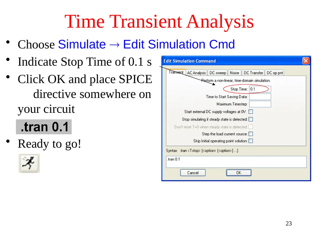
Time Transient Analysis Choose Simulate Edit Simulation Cmd
Indicate Stop Time of 0.1 s
Click OK and place SPICE directive somewhere on your circuit
Ready to go! 23<br>
Indicate Stop Time of 0.1 s
Click OK and place SPICE directive somewhere on your circuit
Ready to go! 23<br>
24
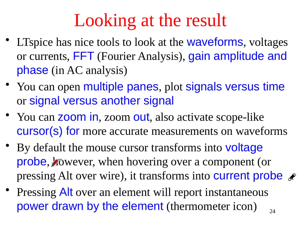
Looking at the result LTspice has nice tools to look at the waveforms, voltages or currents, FFT (Fourier Analysis), gain amplitude and phase (in AC analysis)
You can open multiple panes, plot signals versus time or signal versus another signal
You can zoom in, zoom out, also activate scope-like cursor(s) for more accurate measurements on waveforms
By default the mouse cursor transforms into voltage probe , however, when hovering over a component (or pressing Alt over wire), it transforms into current probe
Pressing Alt over an element will report instantaneous power drawn by the element (thermometer icon) 24<br>
You can open multiple panes, plot signals versus time or signal versus another signal
You can zoom in, zoom out, also activate scope-like cursor(s) for more accurate measurements on waveforms
By default the mouse cursor transforms into voltage probe , however, when hovering over a component (or pressing Alt over wire), it transforms into current probe
Pressing Alt over an element will report instantaneous power drawn by the element (thermometer icon) 24<br>
25
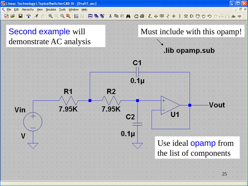
Second example will demonstrate AC analysis Use ideal opamp from the list of components Must include with this opamp! 25<br>
26
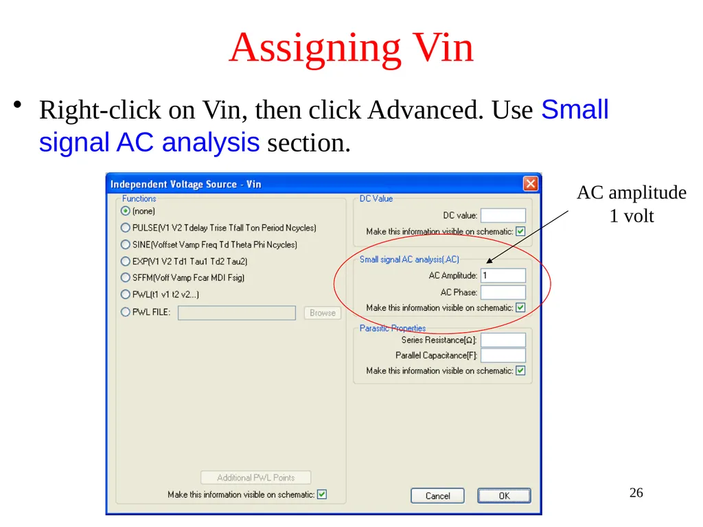
Assigning Vin Right-click on Vin, then click Advanced. Use Small signal AC analysis section. AC amplitude 1 volt 26<br>
27
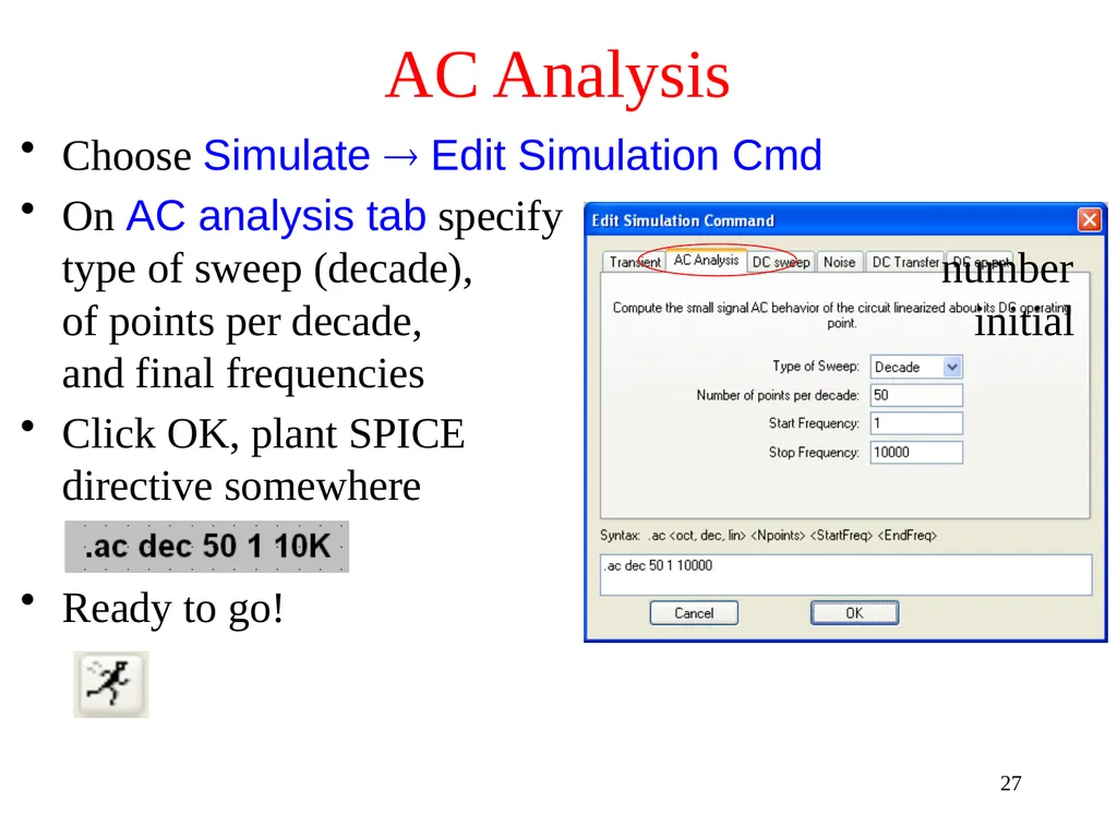
AC Analysis Choose Simulate Edit Simulation Cmd
On AC analysis tab specify type of sweep (decade), number of points per decade, initial and final frequencies
Click OK, plant SPICE directive somewhere
Ready to go! 27<br>
On AC analysis tab specify type of sweep (decade), number of points per decade, initial and final frequencies
Click OK, plant SPICE directive somewhere
Ready to go! 27<br>
28
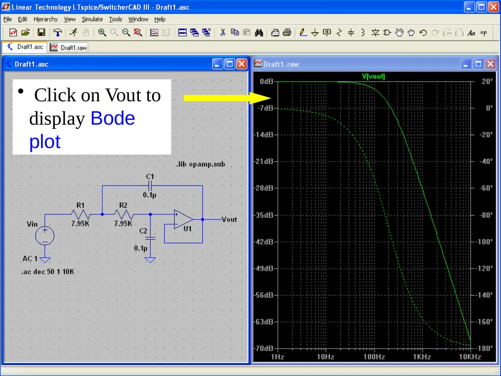
Click on Vout to display Bode plot 28<br>
29
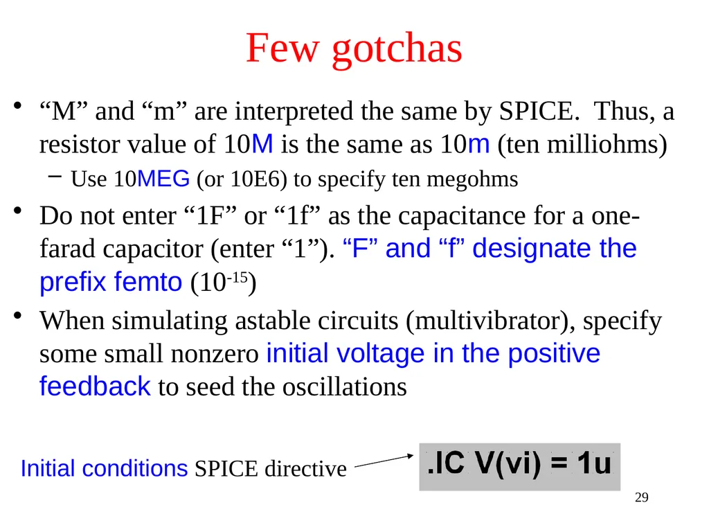
Few gotchas “M” and “m” are interpreted the same by SPICE. Thus, a resistor value of 10M is the same as 10m (ten milliohms)
Use 10MEG (or 10E6) to specify ten megohms
Do not enter “1F” or “1f” as the capacitance for a one-farad capacitor (enter “1”). “F” and “f” designate the prefix femto (10-15)
When simulating astable circuits (multivibrator), specify some small nonzero initial voltage in the positive feedback to seed the oscillations Initial conditions SPICE directive 29<br>
Use 10MEG (or 10E6) to specify ten megohms
Do not enter “1F” or “1f” as the capacitance for a one-farad capacitor (enter “1”). “F” and “f” designate the prefix femto (10-15)
When simulating astable circuits (multivibrator), specify some small nonzero initial voltage in the positive feedback to seed the oscillations Initial conditions SPICE directive 29<br>
30
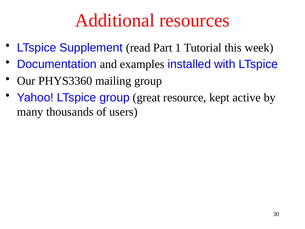
Additional resources LTspice Supplement (read Part 1 Tutorial this week)
Documentation and examples installed with LTspice
Our PHYS3360 mailing group
Yahoo! LTspice group (great resource, kept active by many thousands of users) 30<br>
Documentation and examples installed with LTspice
Our PHYS3360 mailing group
Yahoo! LTspice group (great resource, kept active by many thousands of users) 30<br>