
Crane Rigging Basic Safety DISCLAIMER This
EM
Published · 103 slides · 0 views

1 / 1




Description
Crane Rigging Basic Safety DISCLAIMER This training material presents very important, pertinent information. It should not be assumed, however, that this program satisfies every legal requirement of every state. Some states require the
Related Topics
Share
Embed code
Download this presentation From Below
"Crane Rigging Basic Safety DISCLAIMER This" is the property of its rightful owner. Permission is granted to download and print the materials on this website for personal, non-commercial use only, and to display it on your personal computer provided you do not modify the materials and that you retain all copyright notices contained in the materials. By downloading content from our website, you accept the terms of this agreement.
Presentation Transcript
01
Crane Rigging Basic Safety<br>
02
DISCLAIMER
This training material presents very important, pertinent information. It should not be assumed, however, that this program satisfies every legal requirement of every state. Some states require the training be developed and delivered by an individual with specific training and experience.
This training is AWARENESS LEVEL and does not authorize any person to perform work or validate their level of competency; it must be supplemented with operation and process-specific assessments and training, as well as management oversight, to assure that all training is understood and followed. Your organization must do an evaluation of all exposures and applicable codes and regulations. In addition, establish proper controls, training, and protective measures to effectively control exposures and assure compliance.
This program is neither a determination that the conditions and practices of your organization are safe, nor a warranty that reliance upon this program will prevent accidents and losses or satisfy local, state, or federal regulations. How to Use this Presentation This presentation contains base material for use in an instructor-led training setting. You may modify this presentation to satisfy the specific training needs of your organization.
On some slides, the display text is supplemented with additional material in the slide notes.
This content is licensed for modification and use in a classroom setting. You may not redistribute this material in any form. Introduction<br>
This training is AWARENESS LEVEL and does not authorize any person to perform work or validate their level of competency; it must be supplemented with operation and process-specific assessments and training, as well as management oversight, to assure that all training is understood and followed. Your organization must do an evaluation of all exposures and applicable codes and regulations. In addition, establish proper controls, training, and protective measures to effectively control exposures and assure compliance.
This program is neither a determination that the conditions and practices of your organization are safe, nor a warranty that reliance upon this program will prevent accidents and losses or satisfy local, state, or federal regulations. How to Use this Presentation This presentation contains base material for use in an instructor-led training setting. You may modify this presentation to satisfy the specific training needs of your organization.
On some slides, the display text is supplemented with additional material in the slide notes.
This content is licensed for modification and use in a classroom setting. You may not redistribute this material in any form. Introduction<br>
03
Introduction Safety from the Ground Up
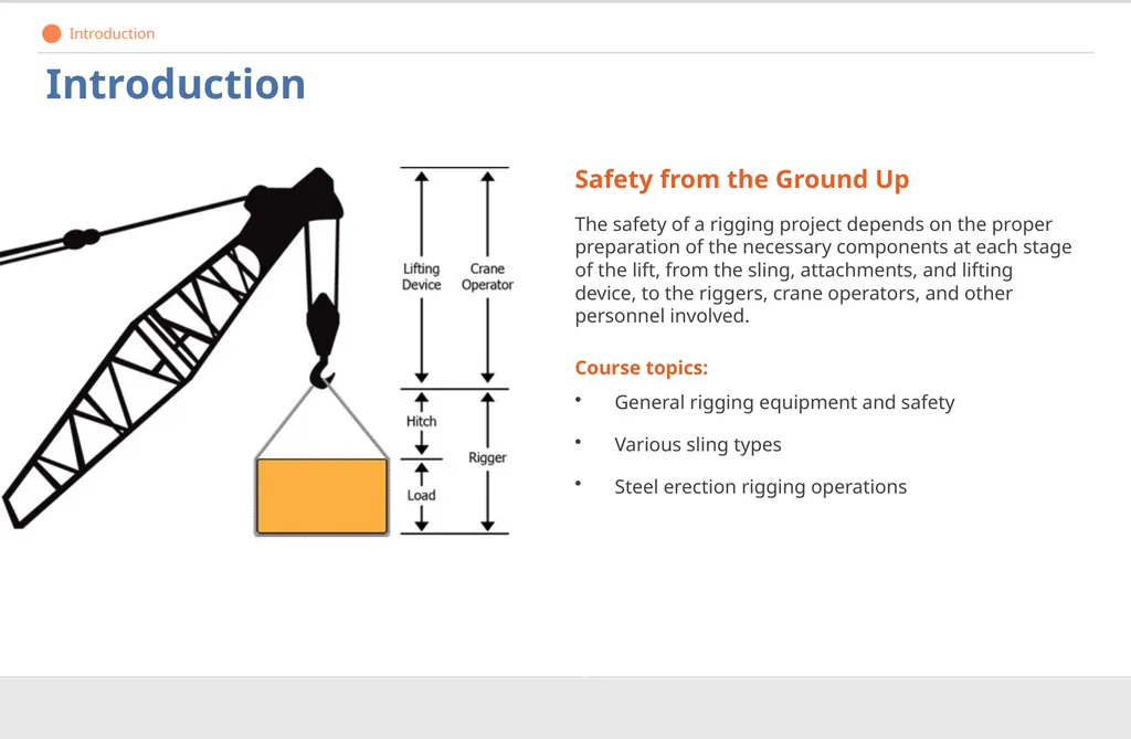
The safety of a rigging project depends on the proper preparation of the necessary components at each stage of the lift, from the sling, attachments, and lifting device, to the riggers, crane operators, and other personnel involved.
Course topics:
General rigging equipment and safety
Various sling types
Steel erection rigging operations Introduction<br>
The safety of a rigging project depends on the proper preparation of the necessary components at each stage of the lift, from the sling, attachments, and lifting device, to the riggers, crane operators, and other personnel involved.
Course topics:
General rigging equipment and safety
Various sling types
Steel erection rigging operations Introduction<br>
04
Introduction Course Overview General Rigging Safety
Alloy Steel Chain Slings
Wire Rope Slings
Metal Mesh Slings
Natural and Synthetic Fiber Rope
Synthetic Web Slings
Steel Erection Rigging
Hand Signals<br>
Alloy Steel Chain Slings
Wire Rope Slings
Metal Mesh Slings
Natural and Synthetic Fiber Rope
Synthetic Web Slings
Steel Erection Rigging
Hand Signals<br>
05
General Rigging Safety What you need to know:
General safety practices
Inspection requirements
Proper identification of equipment limits
Proper storage of equipment
Hitches and slings 1<br>
General safety practices
Inspection requirements
Proper identification of equipment limits
Proper storage of equipment
Hitches and slings 1<br>
06
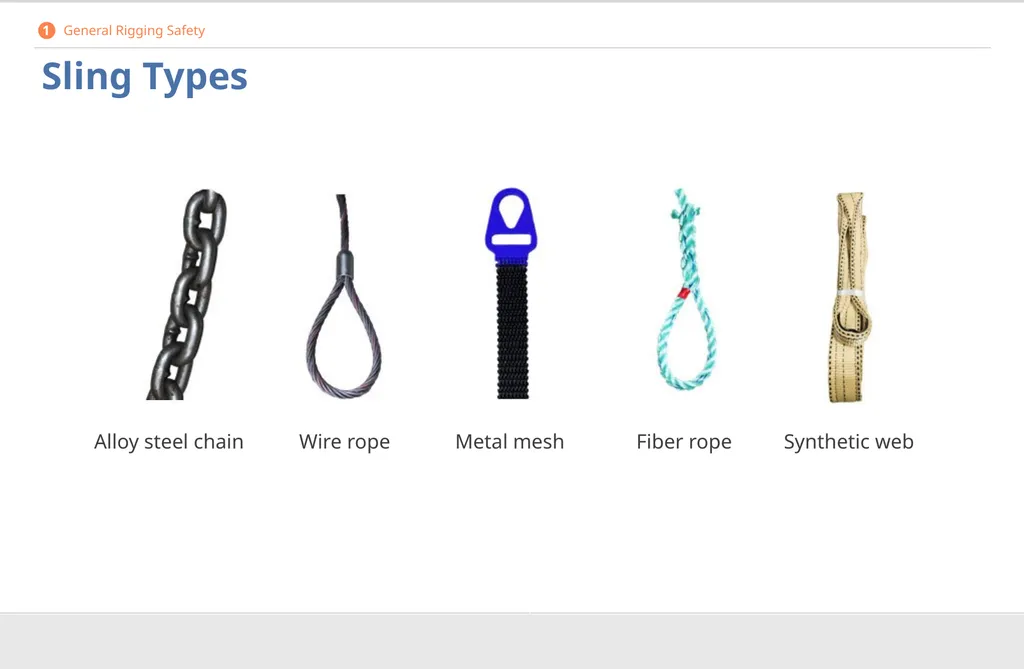
Sling Types Alloy steel chain Wire rope Metal mesh Fiber rope Synthetic web 1 General Rigging Safety<br>
07
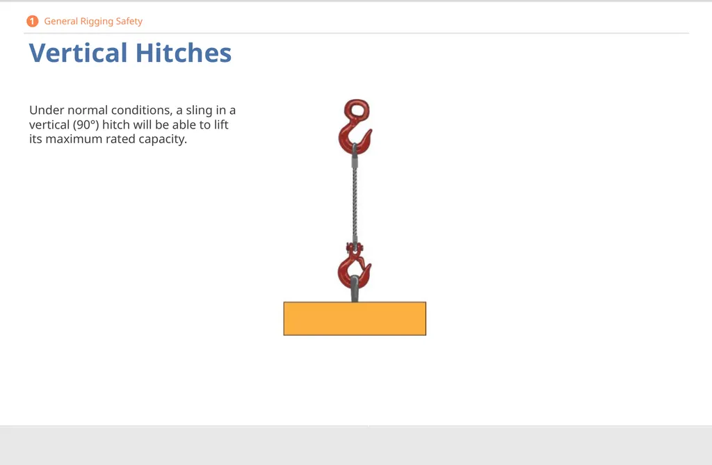
Vertical Hitches Under normal conditions, a sling in a vertical (90°) hitch will be able to lift its maximum rated capacity. 1 General Rigging Safety<br>
08
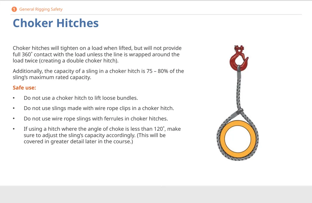
Choker Hitches Choker hitches will tighten on a load when lifted, but will not provide full 360˚ contact with the load unless the line is wrapped around the load twice (creating a double choker hitch).
Additionally, the capacity of a sling in a choker hitch is 75 – 80% of the sling’s maximum rated capacity.
Safe use:
Do not use a choker hitch to lift loose bundles.
Do not use slings made with wire rope clips in a choker hitch.
Do not use wire rope slings with ferrules in choker hitches.
If using a hitch where the angle of choke is less than 120˚, make sure to adjust the sling’s capacity accordingly. (This will be covered in greater detail later in the course.) 1 General Rigging Safety<br>
Additionally, the capacity of a sling in a choker hitch is 75 – 80% of the sling’s maximum rated capacity.
Safe use:
Do not use a choker hitch to lift loose bundles.
Do not use slings made with wire rope clips in a choker hitch.
Do not use wire rope slings with ferrules in choker hitches.
If using a hitch where the angle of choke is less than 120˚, make sure to adjust the sling’s capacity accordingly. (This will be covered in greater detail later in the course.) 1 General Rigging Safety<br>
09
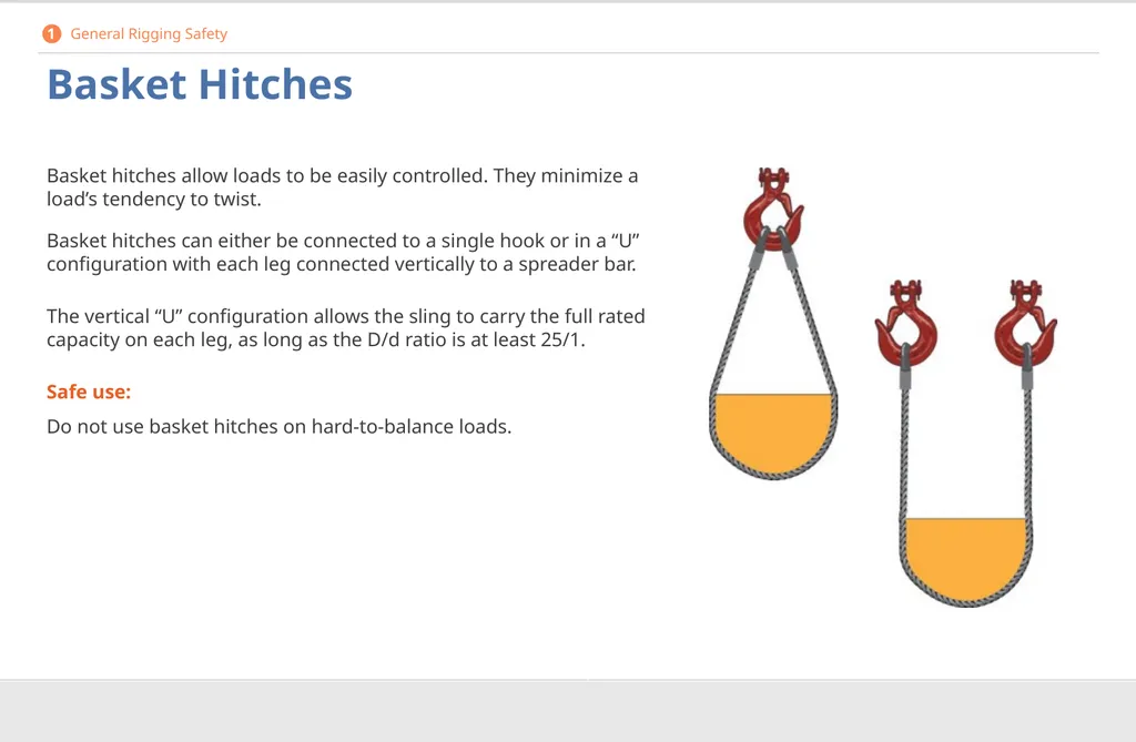
Basket Hitches Basket hitches allow loads to be easily controlled. They minimize a load’s tendency to twist.
Basket hitches can either be connected to a single hook or in a “U” configuration with each leg connected vertically to a spreader bar.
The vertical “U” configuration allows the sling to carry the full rated capacity on each leg, as long as the D/d ratio is at least 25/1.
Safe use:
Do not use basket hitches on hard-to-balance loads. 1 General Rigging Safety<br>
Basket hitches can either be connected to a single hook or in a “U” configuration with each leg connected vertically to a spreader bar.
The vertical “U” configuration allows the sling to carry the full rated capacity on each leg, as long as the D/d ratio is at least 25/1.
Safe use:
Do not use basket hitches on hard-to-balance loads. 1 General Rigging Safety<br>
10
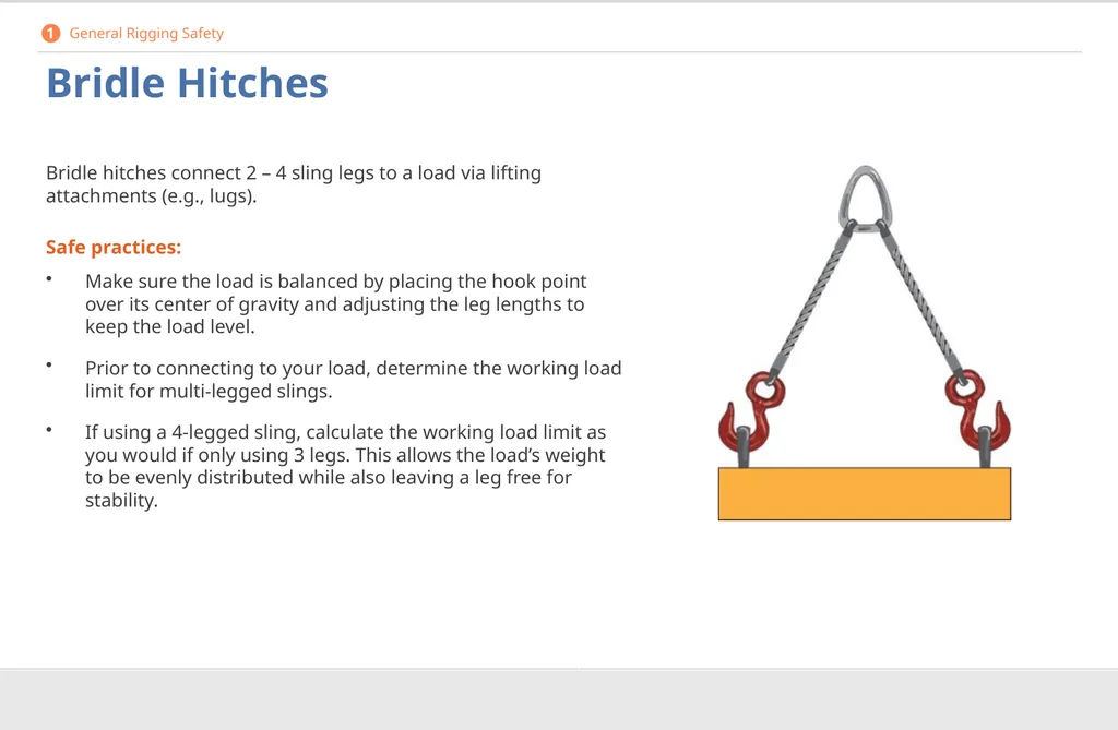
Bridle Hitches Bridle hitches connect 2 – 4 sling legs to a load via lifting attachments (e.g., lugs).
Safe practices:
Make sure the load is balanced by placing the hook point over its center of gravity and adjusting the leg lengths to keep the load level.
Prior to connecting to your load, determine the working load limit for multi-legged slings.
If using a 4-legged sling, calculate the working load limit as you would if only using 3 legs. This allows the load’s weight to be evenly distributed while also leaving a leg free for stability. 1 General Rigging Safety<br>
Safe practices:
Make sure the load is balanced by placing the hook point over its center of gravity and adjusting the leg lengths to keep the load level.
Prior to connecting to your load, determine the working load limit for multi-legged slings.
If using a 4-legged sling, calculate the working load limit as you would if only using 3 legs. This allows the load’s weight to be evenly distributed while also leaving a leg free for stability. 1 General Rigging Safety<br>
11
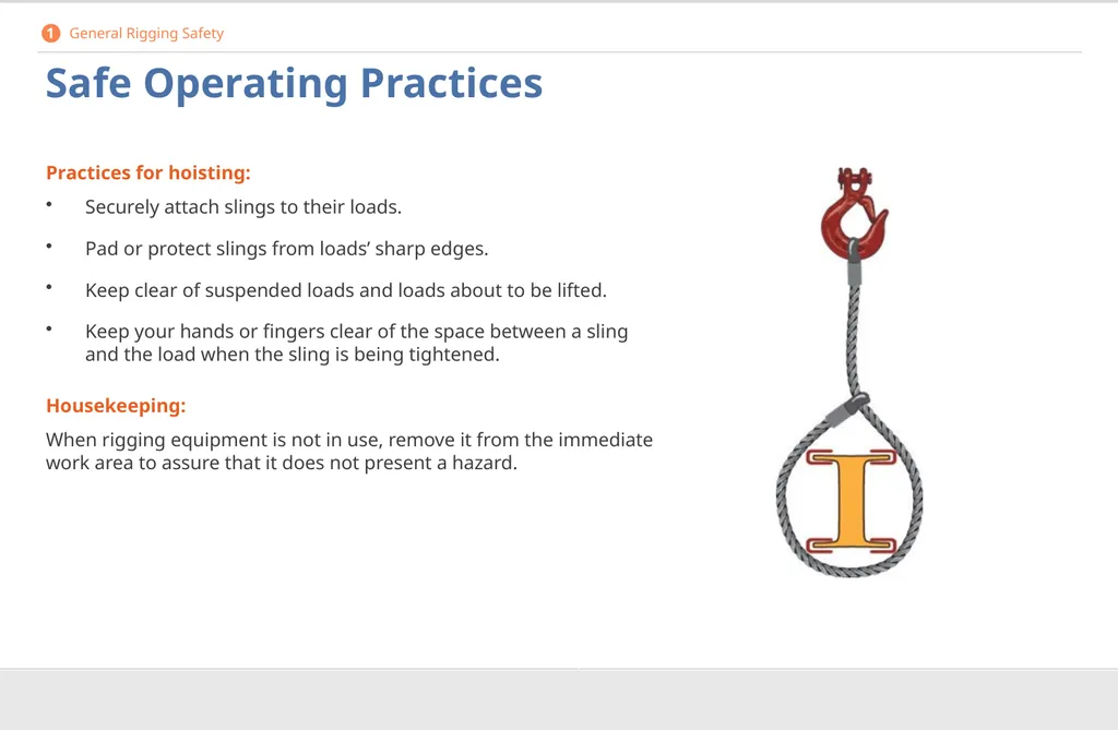
Safe Operating Practices Practices for hoisting:
Securely attach slings to their loads.
Pad or protect slings from loads’ sharp edges.
Keep clear of suspended loads and loads about to be lifted.
Keep your hands or fingers clear of the space between a sling and the load when the sling is being tightened.
Housekeeping:
When rigging equipment is not in use, remove it from the immediate work area to assure that it does not present a hazard. 1 General Rigging Safety<br>
Securely attach slings to their loads.
Pad or protect slings from loads’ sharp edges.
Keep clear of suspended loads and loads about to be lifted.
Keep your hands or fingers clear of the space between a sling and the load when the sling is being tightened.
Housekeeping:
When rigging equipment is not in use, remove it from the immediate work area to assure that it does not present a hazard. 1 General Rigging Safety<br>
12
Sling Safety Restrictions Never:
Load slings in excess of their rated capacities.
Use damaged or defective slings.
Use slings that are shortened with knots, bolts, or other makeshift devices or slings with kinked legs.
Rest a load on a sling. (However, if a load does rest on a sling, do not pull the sling out from under the load.)
Ride on the sling or the load, unless the load is specifically designed and tested for carrying personnel.
Shock load, which is allowing the load to free fall, changing the load’s center of gravity during hoisting, or both. 1 General Rigging Safety<br>
Load slings in excess of their rated capacities.
Use damaged or defective slings.
Use slings that are shortened with knots, bolts, or other makeshift devices or slings with kinked legs.
Rest a load on a sling. (However, if a load does rest on a sling, do not pull the sling out from under the load.)
Ride on the sling or the load, unless the load is specifically designed and tested for carrying personnel.
Shock load, which is allowing the load to free fall, changing the load’s center of gravity during hoisting, or both. 1 General Rigging Safety<br>
13
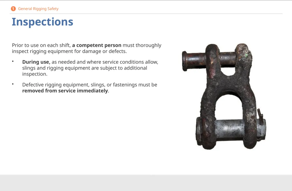
Inspections Prior to use on each shift, a competent person must thoroughly inspect rigging equipment for damage or defects.
During use, as needed and where service conditions allow, slings and rigging equipment are subject to additional inspection.
Defective rigging equipment, slings, or fastenings must be removed from service immediately. 1 General Rigging Safety<br>
During use, as needed and where service conditions allow, slings and rigging equipment are subject to additional inspection.
Defective rigging equipment, slings, or fastenings must be removed from service immediately. 1 General Rigging Safety<br>
14
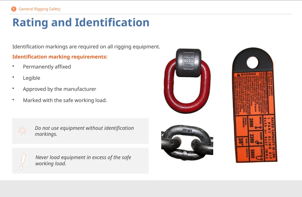
Rating and Identification Identification markings are required on all rigging equipment.
Identification marking requirements:
Permanently affixed
Legible
Approved by the manufacturer
Marked with the safe working load. 1 General Rigging Safety ! * Never load equipment in excess of the safe working load. Do not use equipment without identification markings.<br>
Identification marking requirements:
Permanently affixed
Legible
Approved by the manufacturer
Marked with the safe working load. 1 General Rigging Safety ! * Never load equipment in excess of the safe working load. Do not use equipment without identification markings.<br>
15
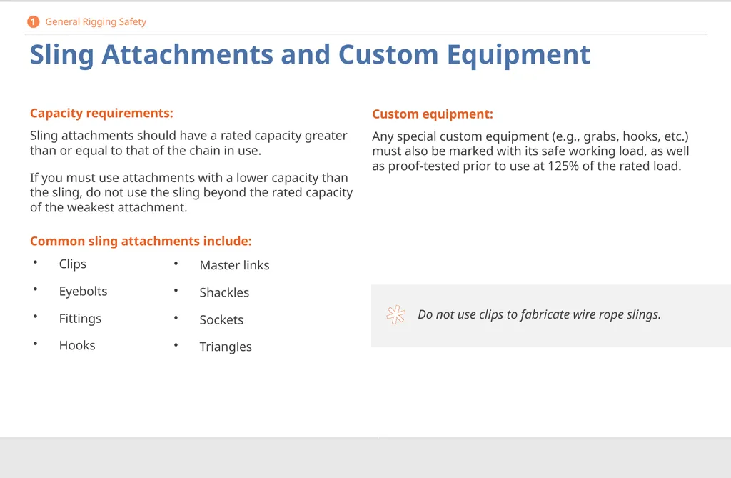
* Sling Attachments and Custom Equipment Capacity requirements:
Sling attachments should have a rated capacity greater than or equal to that of the chain in use.
If you must use attachments with a lower capacity than the sling, do not use the sling beyond the rated capacity of the weakest attachment.
Common sling attachments include: Custom equipment:
Any special custom equipment (e.g., grabs, hooks, etc.) must also be marked with its safe working load, as well as proof-tested prior to use at 125% of the rated load. Master links
Shackles
Sockets
Triangles Do not use clips to fabricate wire rope slings. Clips
Eyebolts
Fittings
Hooks 1 General Rigging Safety<br>
Sling attachments should have a rated capacity greater than or equal to that of the chain in use.
If you must use attachments with a lower capacity than the sling, do not use the sling beyond the rated capacity of the weakest attachment.
Common sling attachments include: Custom equipment:
Any special custom equipment (e.g., grabs, hooks, etc.) must also be marked with its safe working load, as well as proof-tested prior to use at 125% of the rated load. Master links
Shackles
Sockets
Triangles Do not use clips to fabricate wire rope slings. Clips
Eyebolts
Fittings
Hooks 1 General Rigging Safety<br>
16
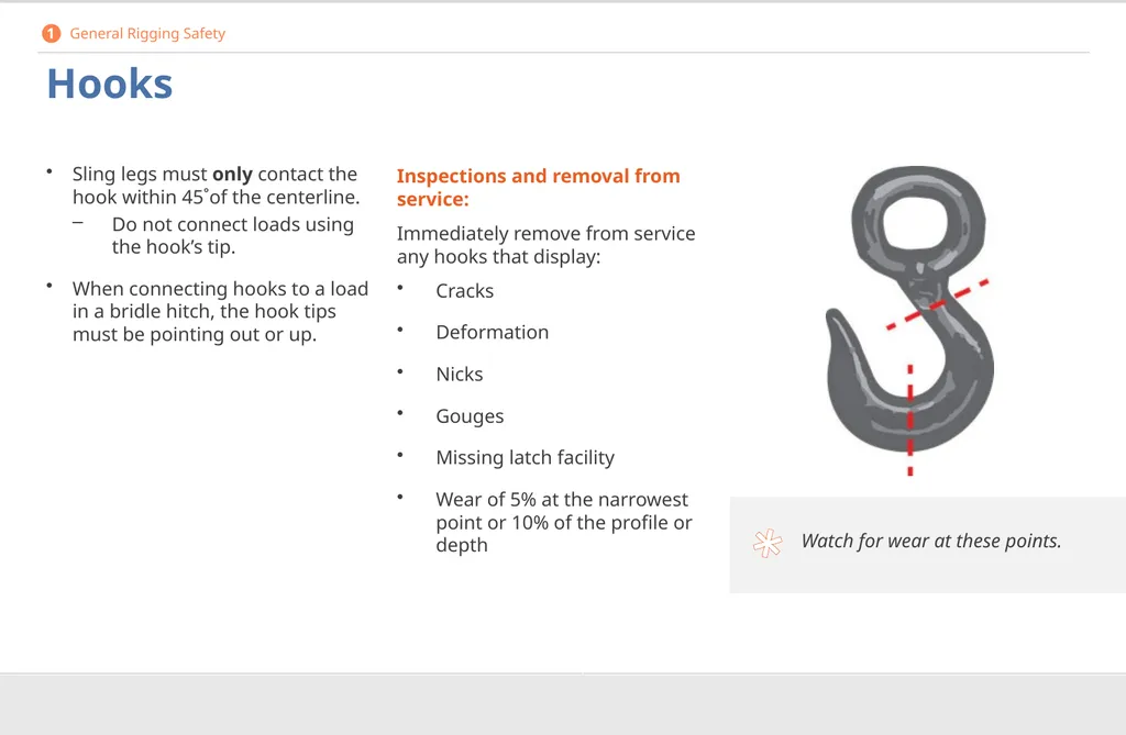
Hooks Sling legs must only contact the hook within 45˚of the centerline.
Do not connect loads using the hook’s tip.
When connecting hooks to a load in a bridle hitch, the hook tips must be pointing out or up. Watch for wear at these points. * 1 General Rigging Safety Inspections and removal from service:
Immediately remove from service any hooks that display:
Cracks
Deformation
Nicks
Gouges
Missing latch facility
Wear of 5% at the narrowest point or 10% of the profile or depth<br>
Do not connect loads using the hook’s tip.
When connecting hooks to a load in a bridle hitch, the hook tips must be pointing out or up. Watch for wear at these points. * 1 General Rigging Safety Inspections and removal from service:
Immediately remove from service any hooks that display:
Cracks
Deformation
Nicks
Gouges
Missing latch facility
Wear of 5% at the narrowest point or 10% of the profile or depth<br>
17
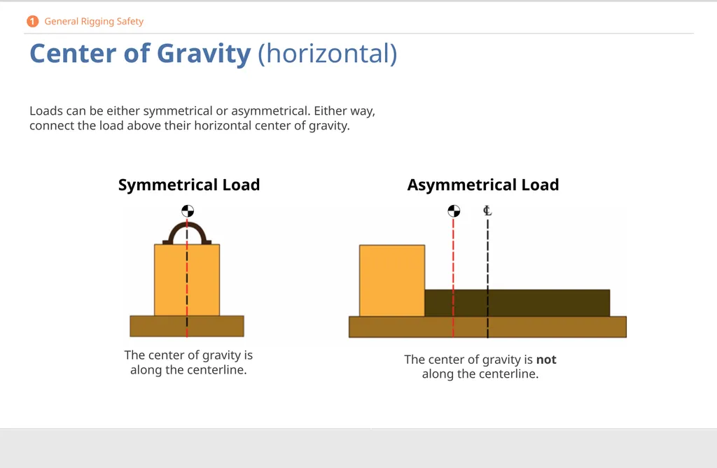
Center of Gravity (horizontal) Loads can be either symmetrical or asymmetrical. Either way, connect the load above their horizontal center of gravity. Symmetrical Load Asymmetrical Load The center of gravity is along the centerline. The center of gravity is not along the centerline. 1 General Rigging Safety<br>
18
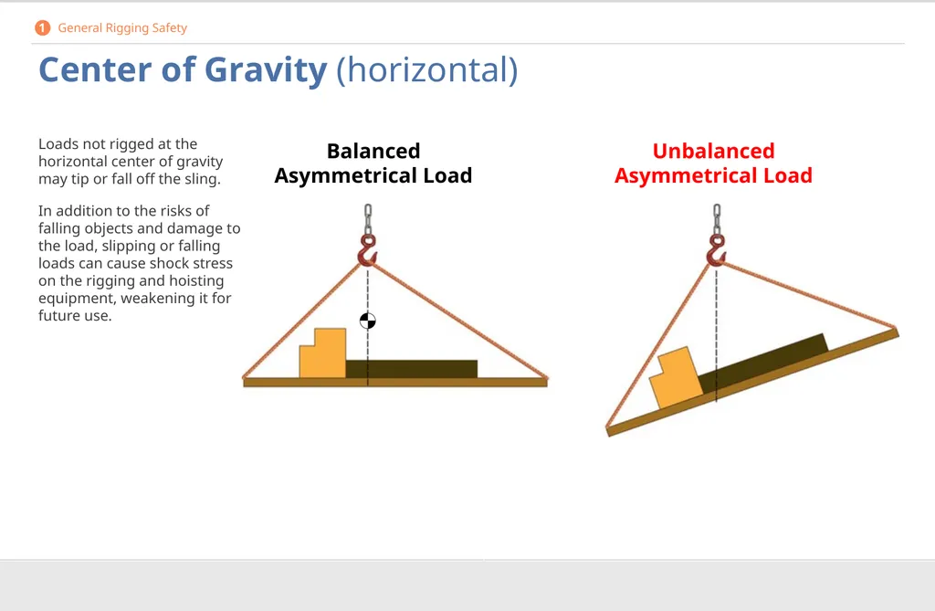
Center of Gravity (horizontal) Loads not rigged at the horizontal center of gravity may tip or fall off the sling.
In addition to the risks of falling objects and damage to the load, slipping or falling loads can cause shock stress on the rigging and hoisting equipment, weakening it for future use. Balanced
Asymmetrical Load Unbalanced
Asymmetrical Load 1 General Rigging Safety<br>
In addition to the risks of falling objects and damage to the load, slipping or falling loads can cause shock stress on the rigging and hoisting equipment, weakening it for future use. Balanced
Asymmetrical Load Unbalanced
Asymmetrical Load 1 General Rigging Safety<br>
19
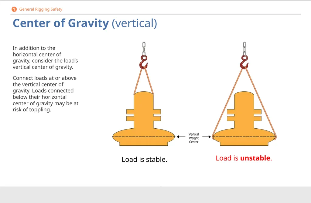
Center of Gravity (vertical) In addition to the horizontal center of gravity, consider the load’s vertical center of gravity.
Connect loads at or above the vertical center of gravity. Loads connected below their horizontal center of gravity may be at risk of toppling. Load is stable. Load is unstable. 1 General Rigging Safety<br>
Connect loads at or above the vertical center of gravity. Loads connected below their horizontal center of gravity may be at risk of toppling. Load is stable. Load is unstable. 1 General Rigging Safety<br>
20
Environmental Conditions Be aware of environmental conditions that may affect the capacity of the sling or other components.
Weather:
Wind
Precipitation
Temperature
Visibility
Worksite features:
Power lines or other overhead obstructions
Uneven or unstable surfaces
Reactive substances:
Chemicals which may damage slings, other rigging components, or personnel If any of these conditions are present, follow the manufacturer recommendations. * 1 General Rigging Safety<br>
Weather:
Wind
Precipitation
Temperature
Visibility
Worksite features:
Power lines or other overhead obstructions
Uneven or unstable surfaces
Reactive substances:
Chemicals which may damage slings, other rigging components, or personnel If any of these conditions are present, follow the manufacturer recommendations. * 1 General Rigging Safety<br>
21
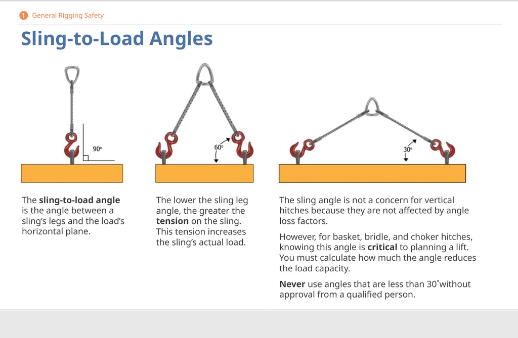
Sling-to-Load Angles The sling-to-load angle is the angle between a sling’s legs and the load’s horizontal plane. The lower the sling leg angle, the greater the tension on the sling. This tension increases the sling’s actual load. The sling angle is not a concern for vertical hitches because they are not affected by angle loss factors.
However, for basket, bridle, and choker hitches, knowing this angle is critical to planning a lift. You must calculate how much the angle reduces the load capacity.
Never use angles that are less than 30˚without approval from a qualified person. 1 General Rigging Safety<br>
However, for basket, bridle, and choker hitches, knowing this angle is critical to planning a lift. You must calculate how much the angle reduces the load capacity.
Never use angles that are less than 30˚without approval from a qualified person. 1 General Rigging Safety<br>
22
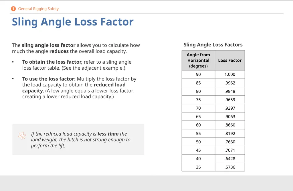
* Sling Angle Loss Factor The sling angle loss factor allows you to calculate how much the angle reduces the overall load capacity.
To obtain the loss factor, refer to a sling angle loss factor table. (See the adjacent example.)
To use the loss factor: Multiply the loss factor by the load capacity to obtain the reduced load capacity. (A low angle equals a lower loss factor, creating a lower reduced load capacity.) Sling Angle Loss Factors If the reduced load capacity is less than the load weight, the hitch is not strong enough to perform the lift. 1 General Rigging Safety<br>
To obtain the loss factor, refer to a sling angle loss factor table. (See the adjacent example.)
To use the loss factor: Multiply the loss factor by the load capacity to obtain the reduced load capacity. (A low angle equals a lower loss factor, creating a lower reduced load capacity.) Sling Angle Loss Factors If the reduced load capacity is less than the load weight, the hitch is not strong enough to perform the lift. 1 General Rigging Safety<br>
23
Activity: Sling Angle Loss Factor Reduced Load Method
The reduced load method uses the sling-to-load angle to determine the reduced load limit. 1 General Rigging Safety Actual Load Method
The actual load method uses inverse proportions to determine the actual load for each sling leg.<br>
The reduced load method uses the sling-to-load angle to determine the reduced load limit. 1 General Rigging Safety Actual Load Method
The actual load method uses inverse proportions to determine the actual load for each sling leg.<br>
24
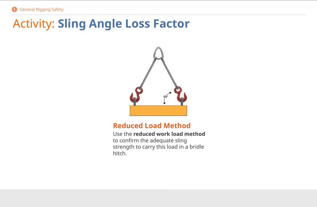
Activity: Sling Angle Loss Factor 1 General Rigging Safety Reduced Load Method
Use the reduced work load method to confirm the adequate sling strength to carry this load in a bridle hitch.<br>
Use the reduced work load method to confirm the adequate sling strength to carry this load in a bridle hitch.<br>
25
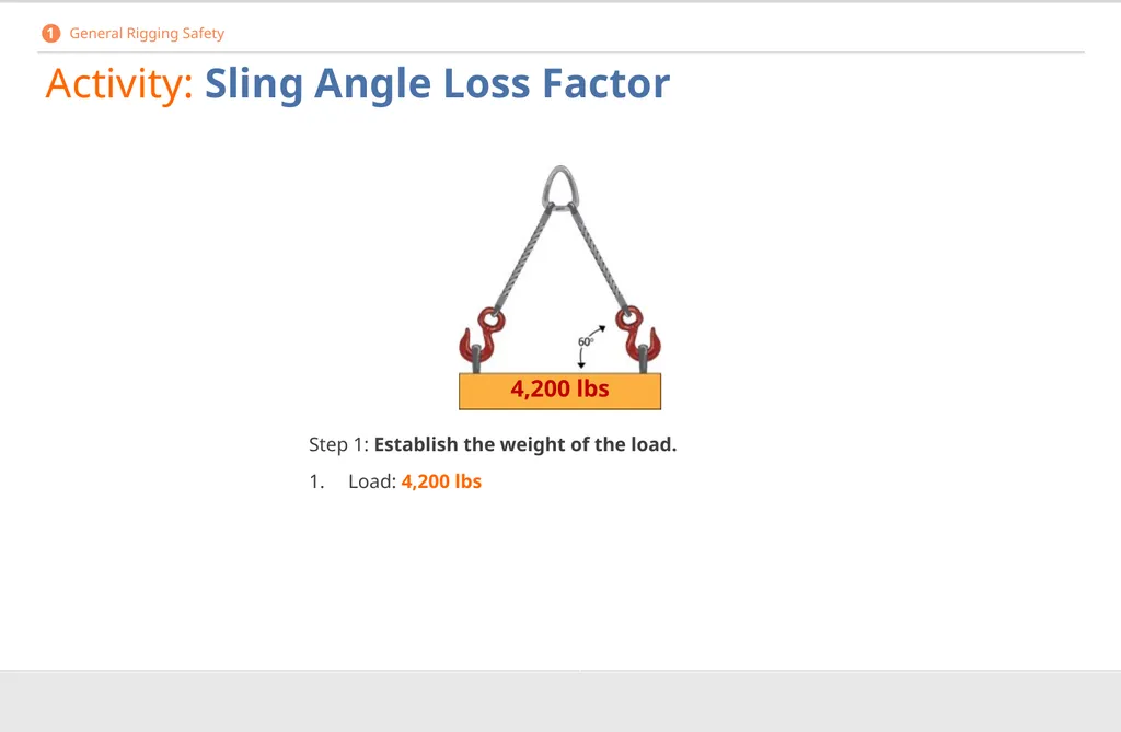
Activity: Sling Angle Loss Factor Step 1: Establish the weight of the load.
Load: 4,200 lbs 4,200 lbs 1 General Rigging Safety<br>
Load: 4,200 lbs 4,200 lbs 1 General Rigging Safety<br>
26
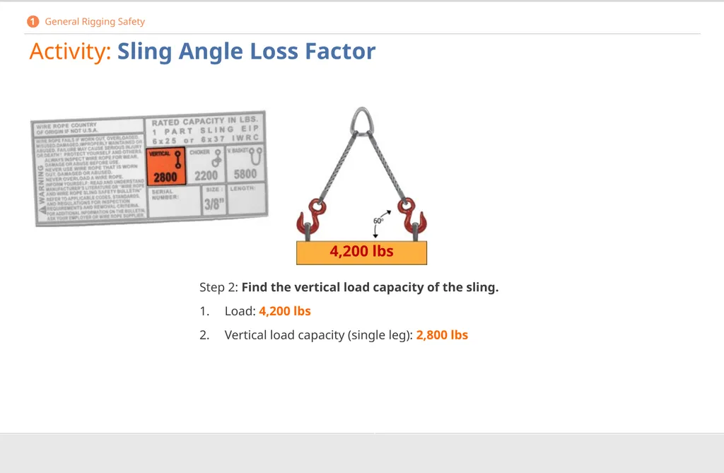
Activity: Sling Angle Loss Factor Step 2: Find the vertical load capacity of the sling.
1. Load: 4,200 lbs
2. Vertical load capacity (single leg): 2,800 lbs 1 General Rigging Safety 4,200 lbs<br>
1. Load: 4,200 lbs
2. Vertical load capacity (single leg): 2,800 lbs 1 General Rigging Safety 4,200 lbs<br>
27
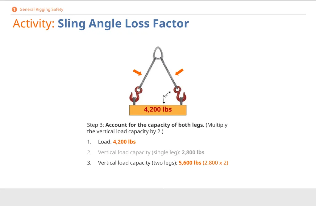
4,200 lbs Activity: Sling Angle Loss Factor Step 3: Account for the capacity of both legs. (Multiply the vertical load capacity by 2.)
1. Load: 4,200 lbs
2. Vertical load capacity (single leg): 2,800 lbs
3. Vertical load capacity (two legs): 5,600 lbs (2,800 x 2) 1 General Rigging Safety<br>
1. Load: 4,200 lbs
2. Vertical load capacity (single leg): 2,800 lbs
3. Vertical load capacity (two legs): 5,600 lbs (2,800 x 2) 1 General Rigging Safety<br>
28
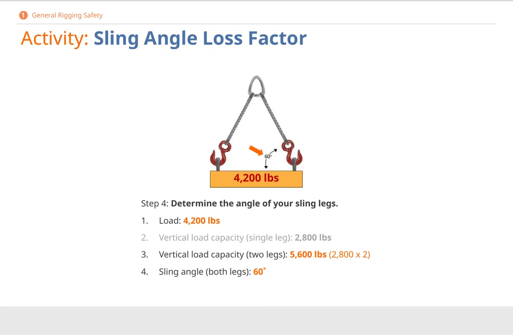
Activity: Sling Angle Loss Factor Step 4: Determine the angle of your sling legs.
1. Load: 4,200 lbs
2. Vertical load capacity (single leg): 2,800 lbs
3. Vertical load capacity (two legs): 5,600 lbs (2,800 x 2)
4. Sling angle (both legs): 60˚ 1 General Rigging Safety 4,200 lbs<br>
1. Load: 4,200 lbs
2. Vertical load capacity (single leg): 2,800 lbs
3. Vertical load capacity (two legs): 5,600 lbs (2,800 x 2)
4. Sling angle (both legs): 60˚ 1 General Rigging Safety 4,200 lbs<br>
29
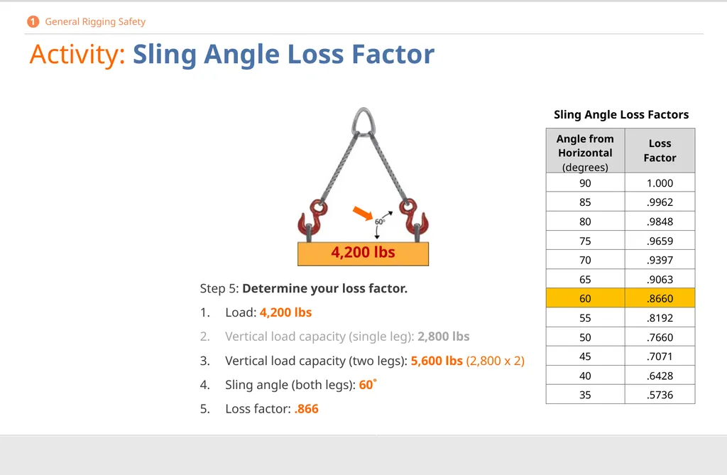
Activity: Sling Angle Loss Factor Step 5: Determine your loss factor.
1. Load: 4,200 lbs
2. Vertical load capacity (single leg): 2,800 lbs
3. Vertical load capacity (two legs): 5,600 lbs (2,800 x 2)
4. Sling angle (both legs): 60˚
5. Loss factor: .866 Sling Angle Loss Factors 1 General Rigging Safety 4,200 lbs<br>
1. Load: 4,200 lbs
2. Vertical load capacity (single leg): 2,800 lbs
3. Vertical load capacity (two legs): 5,600 lbs (2,800 x 2)
4. Sling angle (both legs): 60˚
5. Loss factor: .866 Sling Angle Loss Factors 1 General Rigging Safety 4,200 lbs<br>
30
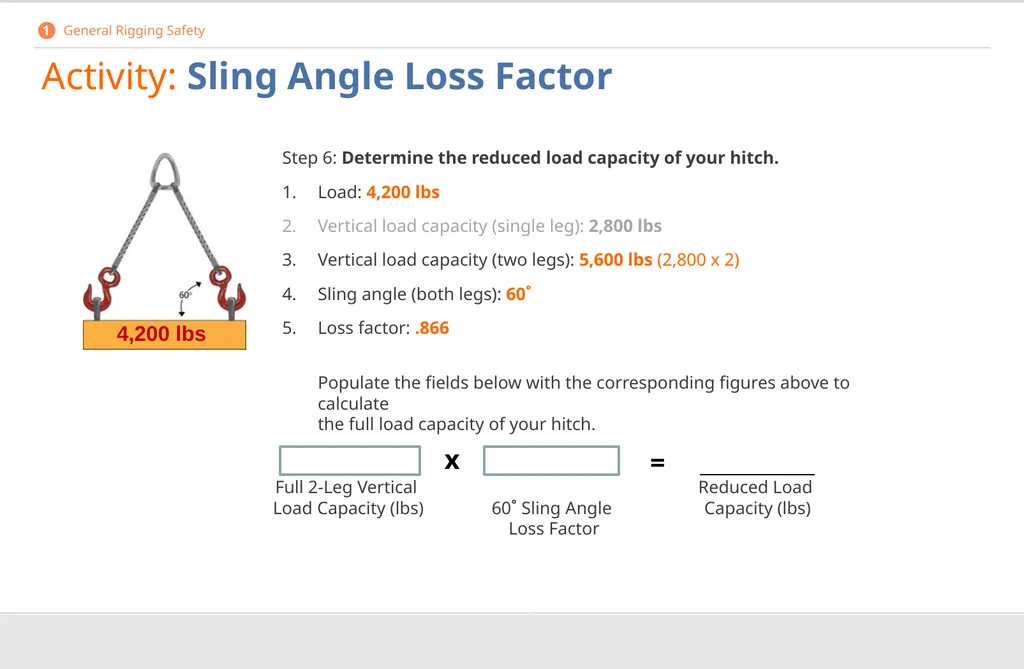
Activity: Sling Angle Loss Factor Step 6: Determine the reduced load capacity of your hitch.
1. Load: 4,200 lbs
2. Vertical load capacity (single leg): 2,800 lbs
3. Vertical load capacity (two legs): 5,600 lbs (2,800 x 2)
4. Sling angle (both legs): 60˚
5. Loss factor: .866
Populate the fields below with the corresponding figures above to calculate the full load capacity of your hitch. 4,200 lbs x = 1 General Rigging Safety Full 2-Leg Vertical
Load Capacity (lbs) 60˚ Sling Angle Loss Factor Reduced Load
Capacity (lbs)<br>
1. Load: 4,200 lbs
2. Vertical load capacity (single leg): 2,800 lbs
3. Vertical load capacity (two legs): 5,600 lbs (2,800 x 2)
4. Sling angle (both legs): 60˚
5. Loss factor: .866
Populate the fields below with the corresponding figures above to calculate the full load capacity of your hitch. 4,200 lbs x = 1 General Rigging Safety Full 2-Leg Vertical
Load Capacity (lbs) 60˚ Sling Angle Loss Factor Reduced Load
Capacity (lbs)<br>
31
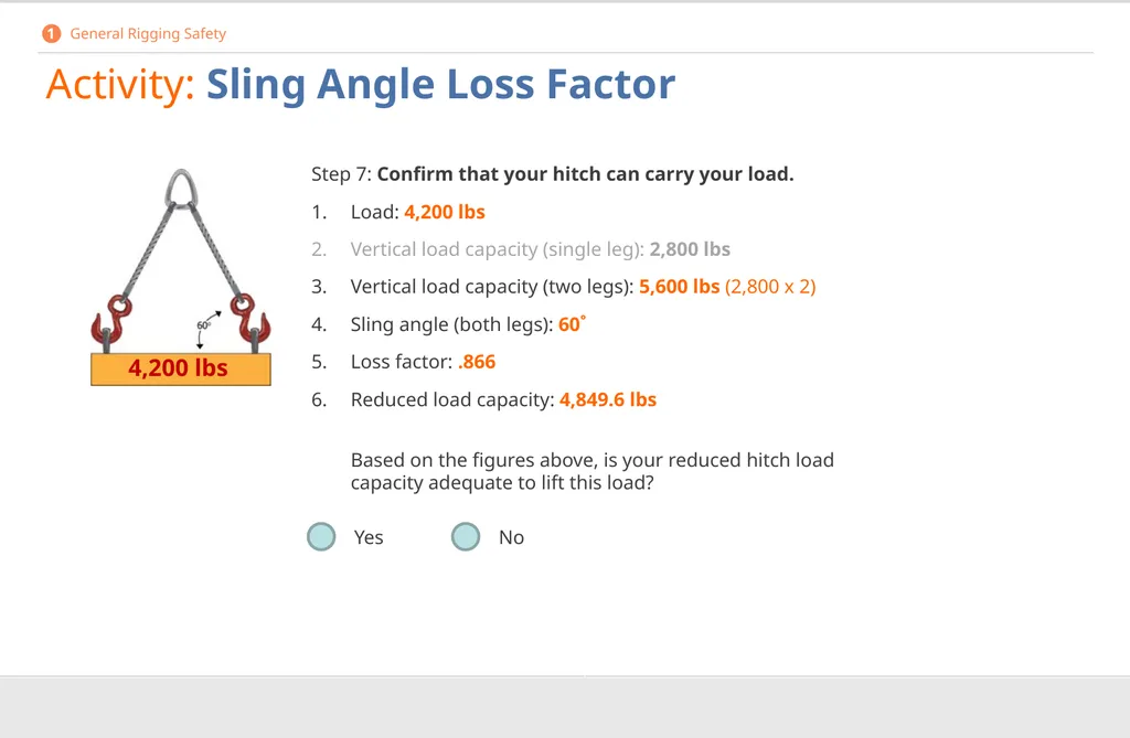
Activity: Sling Angle Loss Factor Step 7: Confirm that your hitch can carry your load.
1. Load: 4,200 lbs
2. Vertical load capacity (single leg): 2,800 lbs
3. Vertical load capacity (two legs): 5,600 lbs (2,800 x 2)
4. Sling angle (both legs): 60˚
5. Loss factor: .866
6. Reduced load capacity: 4,849.6 lbs
Based on the figures above, is your reduced hitch load capacity adequate to lift this load? Yes No 4,200 lbs 1 General Rigging Safety<br>
1. Load: 4,200 lbs
2. Vertical load capacity (single leg): 2,800 lbs
3. Vertical load capacity (two legs): 5,600 lbs (2,800 x 2)
4. Sling angle (both legs): 60˚
5. Loss factor: .866
6. Reduced load capacity: 4,849.6 lbs
Based on the figures above, is your reduced hitch load capacity adequate to lift this load? Yes No 4,200 lbs 1 General Rigging Safety<br>
32
Activity: Sling Angle Loss Factor 1 General Rigging Safety Actual Load Method
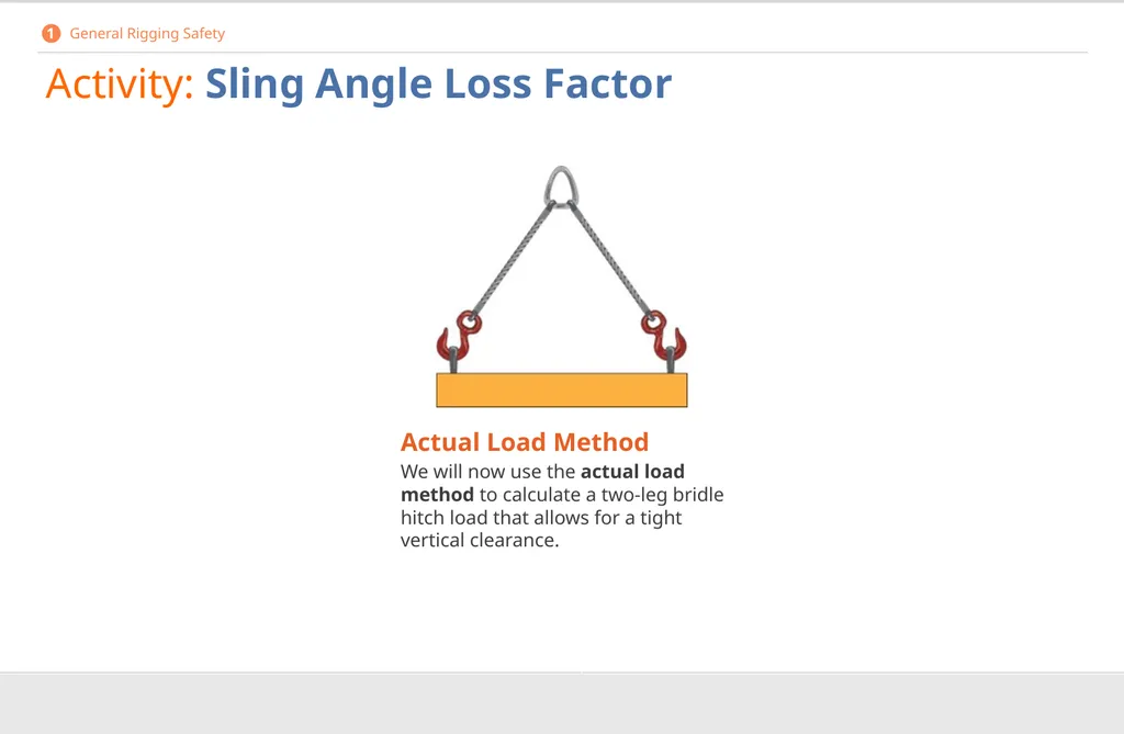
We will now use the actual load method to calculate a two-leg bridle hitch load that allows for a tight vertical clearance.<br>
We will now use the actual load method to calculate a two-leg bridle hitch load that allows for a tight vertical clearance.<br>
33
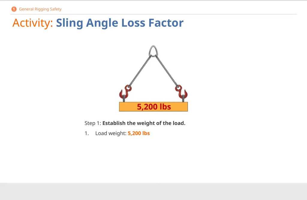
Activity: Sling Angle Loss Factor Step 1: Establish the weight of the load.
1. Load weight: 5,200 lbs 5,200 lbs 1 General Rigging Safety<br>
1. Load weight: 5,200 lbs 5,200 lbs 1 General Rigging Safety<br>
34
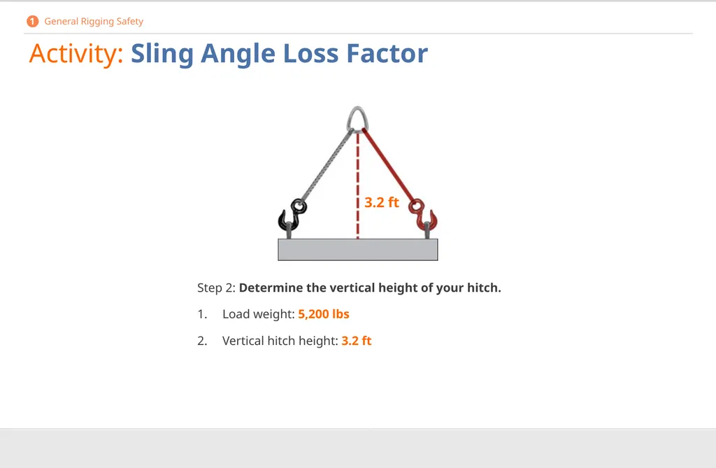
Activity: Sling Angle Loss Factor Step 2: Determine the vertical height of your hitch.
Load weight: 5,200 lbs
Vertical hitch height: 3.2 ft 3.2 ft 1 General Rigging Safety<br>
Load weight: 5,200 lbs
Vertical hitch height: 3.2 ft 3.2 ft 1 General Rigging Safety<br>
35
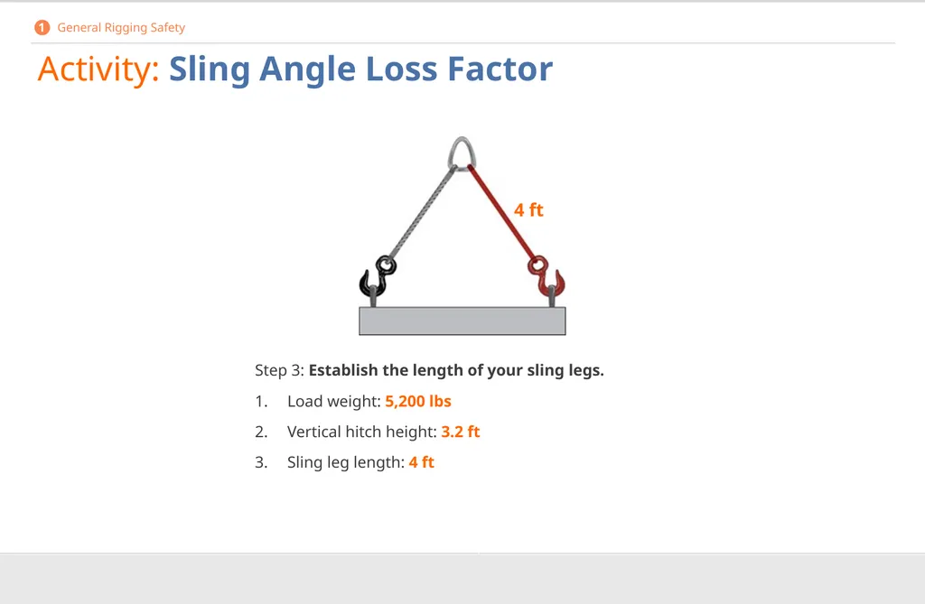
Activity: Sling Angle Loss Factor Step 3: Establish the length of your sling legs.
Load weight: 5,200 lbs
Vertical hitch height: 3.2 ft
Sling leg length: 4 ft 4 ft 1 General Rigging Safety<br>
Load weight: 5,200 lbs
Vertical hitch height: 3.2 ft
Sling leg length: 4 ft 4 ft 1 General Rigging Safety<br>
36
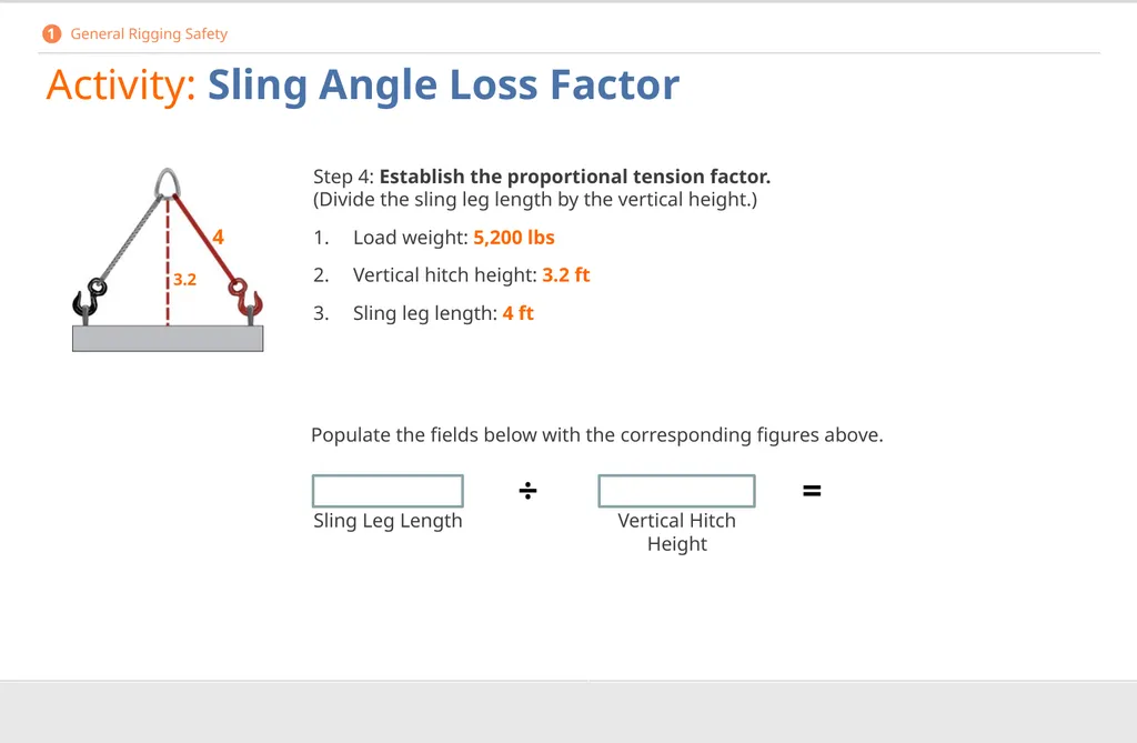
Activity: Sling Angle Loss Factor Step 4: Establish the proportional tension factor. (Divide the sling leg length by the vertical height.)
Load weight: 5,200 lbs
Vertical hitch height: 3.2 ft
Sling leg length: 4 ft Sling Leg Length Vertical Hitch Height ÷ = 3.2 4 Populate the fields below with the corresponding figures above. 1 General Rigging Safety<br>
Load weight: 5,200 lbs
Vertical hitch height: 3.2 ft
Sling leg length: 4 ft Sling Leg Length Vertical Hitch Height ÷ = 3.2 4 Populate the fields below with the corresponding figures above. 1 General Rigging Safety<br>
37
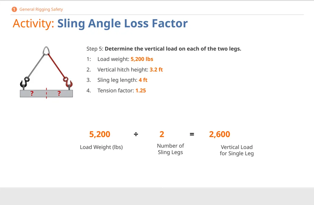
Activity: Sling Angle Loss Factor Step 5: Determine the vertical load on each of the two legs.
1: Load weight: 5,200 lbs
2. Vertical hitch height: 3.2 ft
3. Sling leg length: 4 ft
4. Tension factor: 1.25 5,200 ÷ 2 = 2,600 Load Weight (lbs) Number of Sling Legs Vertical Load for Single Leg ? ? 1 General Rigging Safety<br>
1: Load weight: 5,200 lbs
2. Vertical hitch height: 3.2 ft
3. Sling leg length: 4 ft
4. Tension factor: 1.25 5,200 ÷ 2 = 2,600 Load Weight (lbs) Number of Sling Legs Vertical Load for Single Leg ? ? 1 General Rigging Safety<br>
38
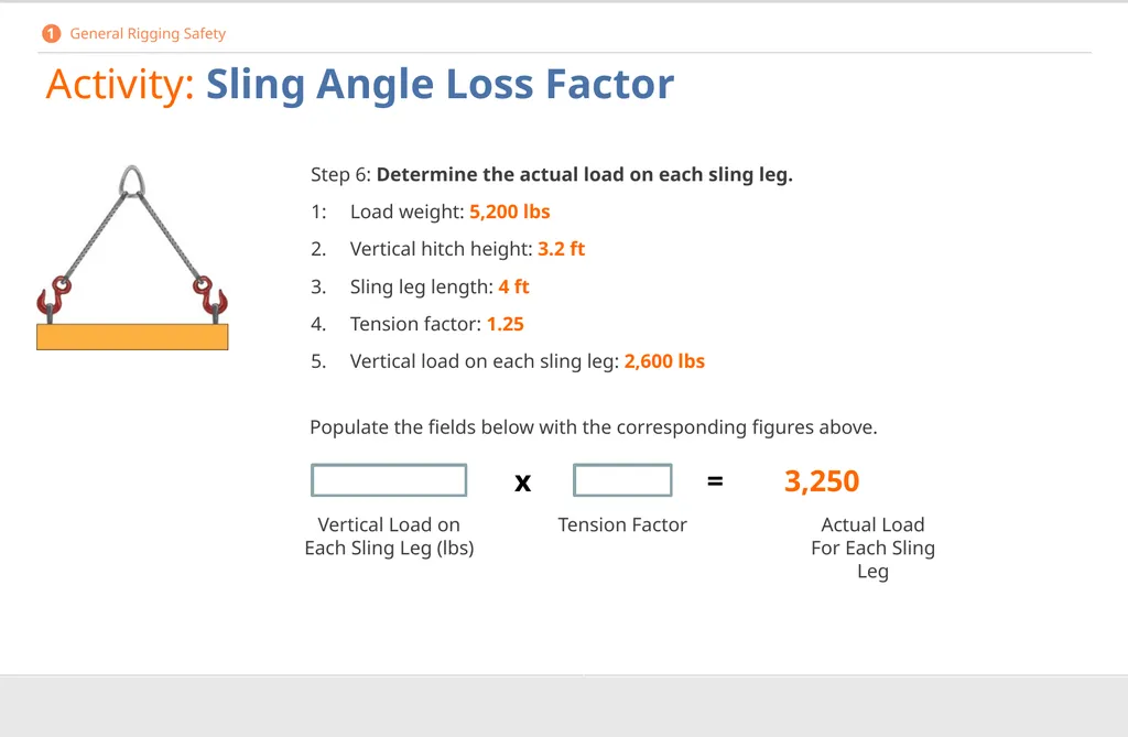
Activity: Sling Angle Loss Factor Step 6: Determine the actual load on each sling leg.
1: Load weight: 5,200 lbs
2. Vertical hitch height: 3.2 ft
3. Sling leg length: 4 ft
4. Tension factor: 1.25
5. Vertical load on each sling leg: 2,600 lbs x = 3,250 Vertical Load on Each Sling Leg (lbs) Tension Factor Actual Load For Each Sling Leg Populate the fields below with the corresponding figures above. 1 General Rigging Safety<br>
1: Load weight: 5,200 lbs
2. Vertical hitch height: 3.2 ft
3. Sling leg length: 4 ft
4. Tension factor: 1.25
5. Vertical load on each sling leg: 2,600 lbs x = 3,250 Vertical Load on Each Sling Leg (lbs) Tension Factor Actual Load For Each Sling Leg Populate the fields below with the corresponding figures above. 1 General Rigging Safety<br>
39
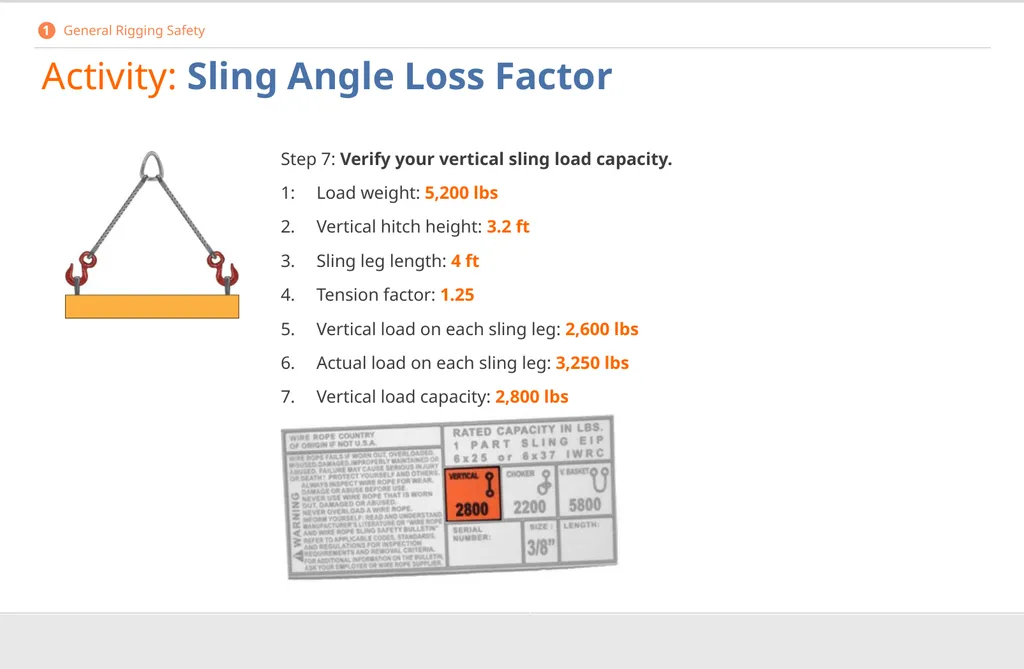
Activity: Sling Angle Loss Factor Step 7: Verify your vertical sling load capacity.
1: Load weight: 5,200 lbs
2. Vertical hitch height: 3.2 ft
3. Sling leg length: 4 ft
4. Tension factor: 1.25
5. Vertical load on each sling leg: 2,600 lbs
6. Actual load on each sling leg: 3,250 lbs
7. Vertical load capacity: 2,800 lbs 1 General Rigging Safety<br>
1: Load weight: 5,200 lbs
2. Vertical hitch height: 3.2 ft
3. Sling leg length: 4 ft
4. Tension factor: 1.25
5. Vertical load on each sling leg: 2,600 lbs
6. Actual load on each sling leg: 3,250 lbs
7. Vertical load capacity: 2,800 lbs 1 General Rigging Safety<br>
40
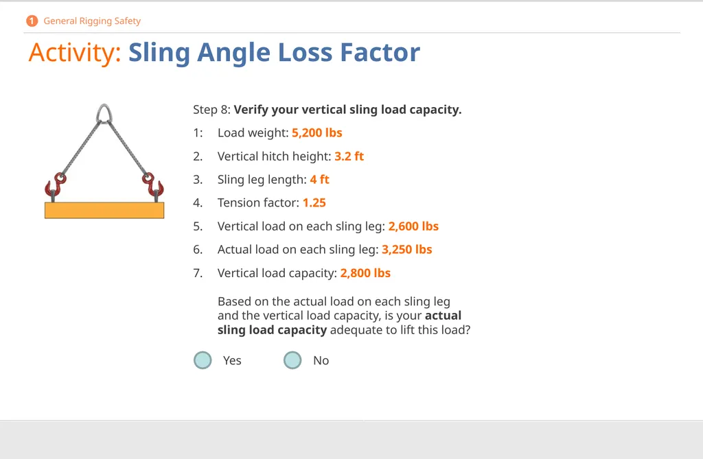
Activity: Sling Angle Loss Factor Step 8: Verify your vertical sling load capacity.
1: Load weight: 5,200 lbs
2. Vertical hitch height: 3.2 ft
3. Sling leg length: 4 ft
4. Tension factor: 1.25
5. Vertical load on each sling leg: 2,600 lbs
6. Actual load on each sling leg: 3,250 lbs
7. Vertical load capacity: 2,800 lbs
Based on the actual load on each sling leg and the vertical load capacity, is your actual sling load capacity adequate to lift this load? Yes No 1 General Rigging Safety<br>
1: Load weight: 5,200 lbs
2. Vertical hitch height: 3.2 ft
3. Sling leg length: 4 ft
4. Tension factor: 1.25
5. Vertical load on each sling leg: 2,600 lbs
6. Actual load on each sling leg: 3,250 lbs
7. Vertical load capacity: 2,800 lbs
Based on the actual load on each sling leg and the vertical load capacity, is your actual sling load capacity adequate to lift this load? Yes No 1 General Rigging Safety<br>
41
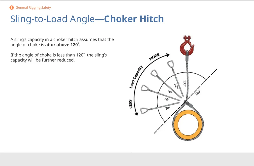
Sling-to-Load Angle—Choker Hitch A sling’s capacity in a choker hitch assumes that the angle of choke is at or above 120˚.
If the angle of choke is less than 120˚, the sling’s capacity will be further reduced. 1 General Rigging Safety<br>
42
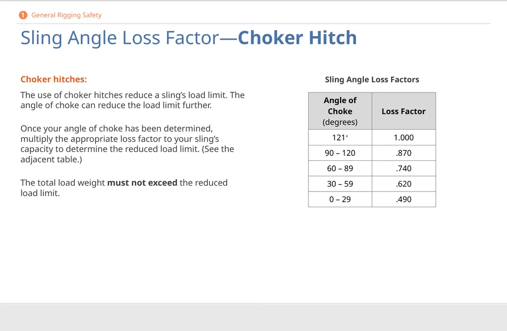
Sling Angle Loss Factor—Choker Hitch Choker hitches:
The use of choker hitches reduce a sling’s load limit. The angle of choke can reduce the load limit further.
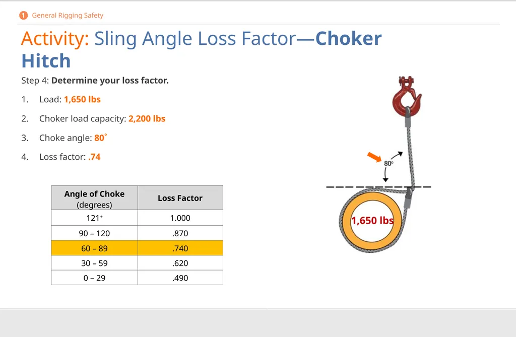
Once your angle of choke has been determined, multiply the appropriate loss factor to your sling’s capacity to determine the reduced load limit. (See the adjacent table.)
The total load weight must not exceed the reduced load limit. Sling Angle Loss Factors 1 General Rigging Safety<br>
The use of choker hitches reduce a sling’s load limit. The angle of choke can reduce the load limit further.
Once your angle of choke has been determined, multiply the appropriate loss factor to your sling’s capacity to determine the reduced load limit. (See the adjacent table.)
The total load weight must not exceed the reduced load limit. Sling Angle Loss Factors 1 General Rigging Safety<br>
43
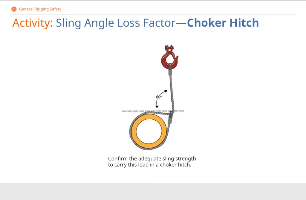
Activity: Sling Angle Loss Factor—Choker Hitch Confirm the adequate sling strength to carry this load in a choker hitch. 1 General Rigging Safety<br>
44
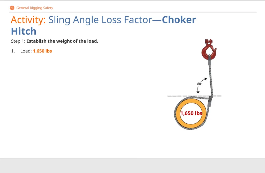
Step 1: Establish the weight of the load.
1. Load: 1,650 lbs 1,650 lbs Activity: Sling Angle Loss Factor—Choker Hitch 1 General Rigging Safety<br>
1. Load: 1,650 lbs 1,650 lbs Activity: Sling Angle Loss Factor—Choker Hitch 1 General Rigging Safety<br>
45
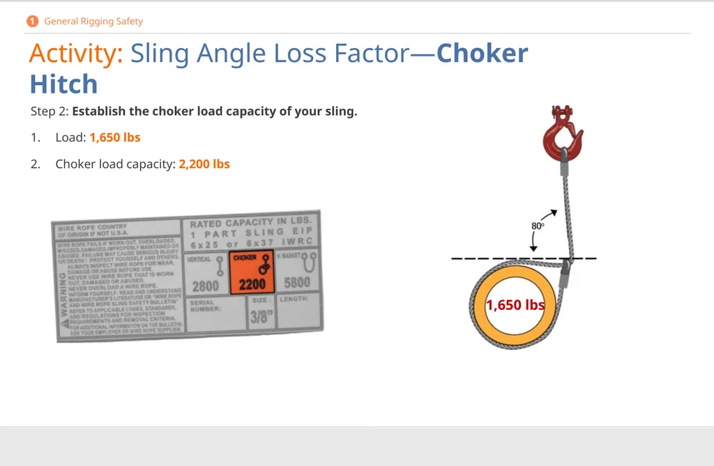
1,650 lbs Step 2: Establish the choker load capacity of your sling.
1. Load: 1,650 lbs
2. Choker load capacity: 2,200 lbs Activity: Sling Angle Loss Factor—Choker Hitch 1 General Rigging Safety<br>
1. Load: 1,650 lbs
2. Choker load capacity: 2,200 lbs Activity: Sling Angle Loss Factor—Choker Hitch 1 General Rigging Safety<br>
46
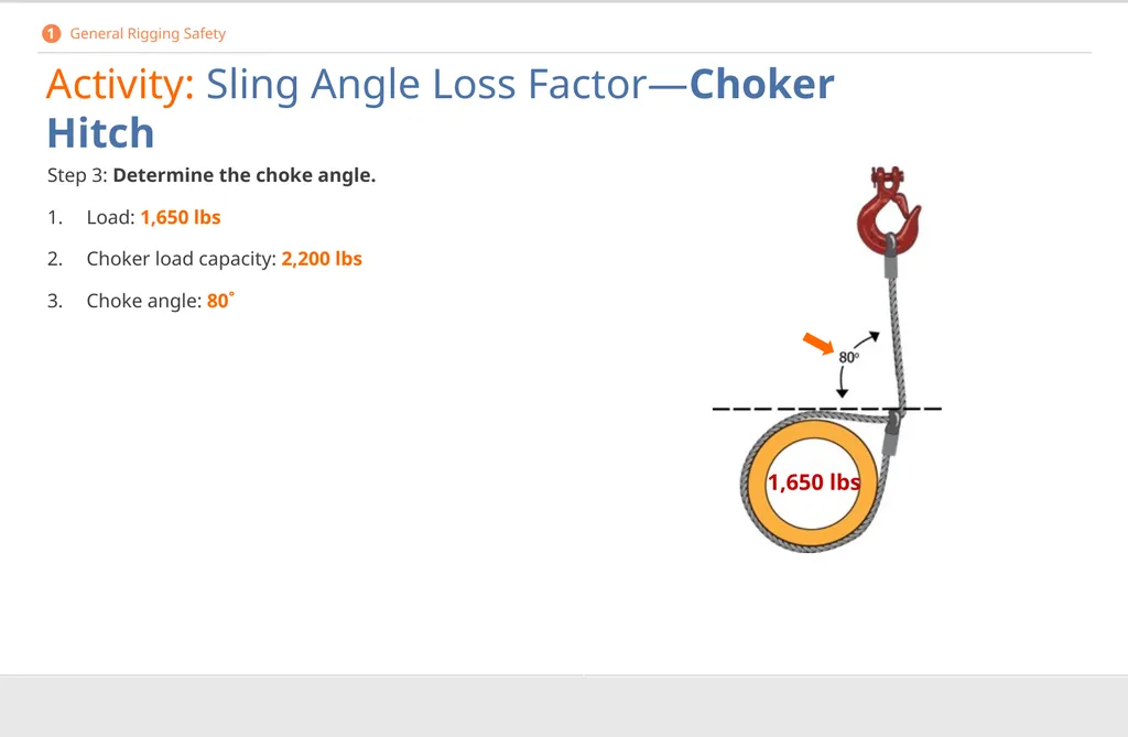
1,650 lbs Step 3: Determine the choke angle.
1. Load: 1,650 lbs
2. Choker load capacity: 2,200 lbs
3. Choke angle: 80˚ Activity: Sling Angle Loss Factor—Choker Hitch 1 General Rigging Safety<br>
1. Load: 1,650 lbs
2. Choker load capacity: 2,200 lbs
3. Choke angle: 80˚ Activity: Sling Angle Loss Factor—Choker Hitch 1 General Rigging Safety<br>
47
1,650 lbs Step 4: Determine your loss factor.
1. Load: 1,650 lbs
2. Choker load capacity: 2,200 lbs
3. Choke angle: 80˚
4. Loss factor: .74 Activity: Sling Angle Loss Factor—Choker Hitch 1 General Rigging Safety<br>
1. Load: 1,650 lbs
2. Choker load capacity: 2,200 lbs
3. Choke angle: 80˚
4. Loss factor: .74 Activity: Sling Angle Loss Factor—Choker Hitch 1 General Rigging Safety<br>
48
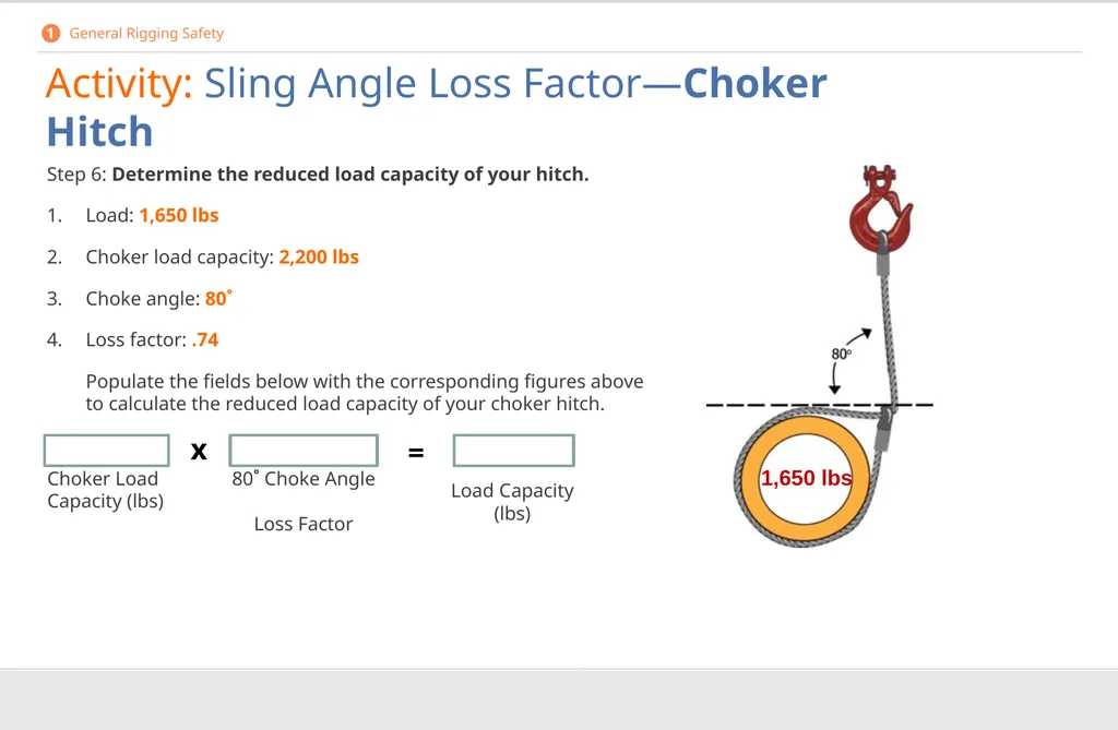
Step 6: Determine the reduced load capacity of your hitch.
1. Load: 1,650 lbs
2. Choker load capacity: 2,200 lbs
3. Choke angle: 80˚
4. Loss factor: .74
Populate the fields below with the corresponding figures above to calculate the reduced load capacity of your choker hitch. 5600
Choker Load Capacity (lbs) .866 80˚ Choke Angle Loss Factor x = Load Capacity (lbs) Activity: Sling Angle Loss Factor—Choker Hitch 1 General Rigging Safety 1,650 lbs<br>
1. Load: 1,650 lbs
2. Choker load capacity: 2,200 lbs
3. Choke angle: 80˚
4. Loss factor: .74
Populate the fields below with the corresponding figures above to calculate the reduced load capacity of your choker hitch. 5600
Choker Load Capacity (lbs) .866 80˚ Choke Angle Loss Factor x = Load Capacity (lbs) Activity: Sling Angle Loss Factor—Choker Hitch 1 General Rigging Safety 1,650 lbs<br>
49
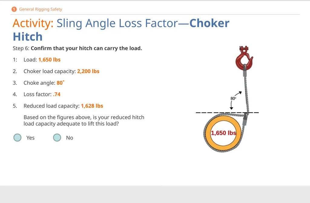
Step 6: Confirm that your hitch can carry the load.
1: Load: 1,650 lbs
2. Choker load capacity: 2,200 lbs
3. Choke angle: 80˚
4. Loss factor: .74
5. Reduced load capacity: 1,628 lbs
Based on the figures above, is your reduced hitch load capacity adequate to lift this load? Yes No Activity: Sling Angle Loss Factor—Choker Hitch 1 General Rigging Safety 1,650 lbs<br>
1: Load: 1,650 lbs
2. Choker load capacity: 2,200 lbs
3. Choke angle: 80˚
4. Loss factor: .74
5. Reduced load capacity: 1,628 lbs
Based on the figures above, is your reduced hitch load capacity adequate to lift this load? Yes No Activity: Sling Angle Loss Factor—Choker Hitch 1 General Rigging Safety 1,650 lbs<br>
50
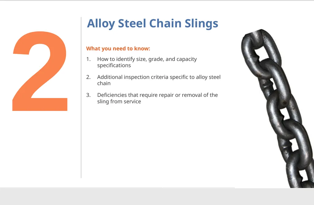
Alloy Steel Chain Slings What you need to know:
How to identify size, grade, and capacity specifications
Additional inspection criteria specific to alloy steel chain
Deficiencies that require repair or removal of the sling from service 2<br>
How to identify size, grade, and capacity specifications
Additional inspection criteria specific to alloy steel chain
Deficiencies that require repair or removal of the sling from service 2<br>
51
Identification Alloy steel chain identification markings must indicate the following:
Size
Grade
Rated capacity
Reach
Manufacturer or fabricator
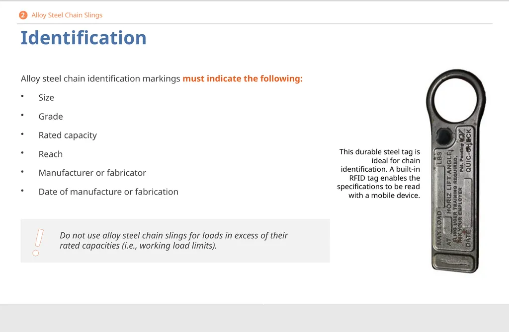
Date of manufacture or fabrication This durable steel tag is ideal for chain identification. A built-in RFID tag enables the specifications to be read with a mobile device. 2 Alloy Steel Chain Slings ! Do not use alloy steel chain slings for loads in excess of their rated capacities (i.e., working load limits).<br>
Size
Grade
Rated capacity
Reach
Manufacturer or fabricator
Date of manufacture or fabrication This durable steel tag is ideal for chain identification. A built-in RFID tag enables the specifications to be read with a mobile device. 2 Alloy Steel Chain Slings ! Do not use alloy steel chain slings for loads in excess of their rated capacities (i.e., working load limits).<br>
52
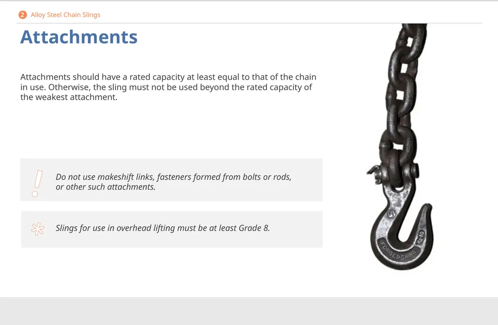
* Attachments Attachments should have a rated capacity at least equal to that of the chain in use. Otherwise, the sling must not be used beyond the rated capacity of the weakest attachment. Slings for use in overhead lifting must be at least Grade 8. 2 Alloy Steel Chain Slings ! Do not use makeshift links, fasteners formed from bolts or rods, or other such attachments.<br>
53
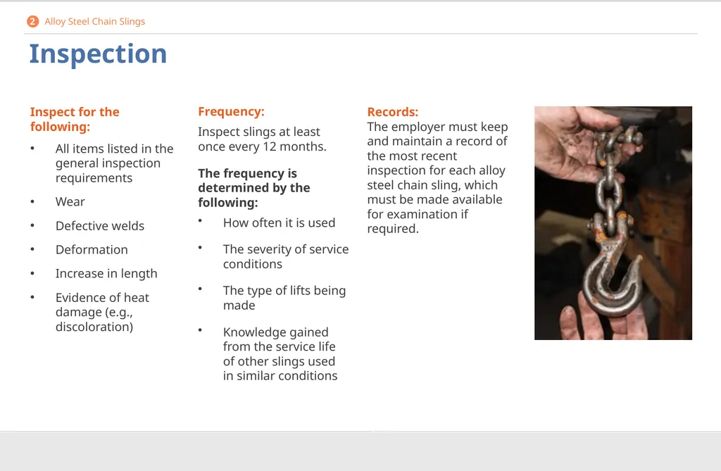
Inspection Frequency:
Inspect slings at least once every 12 months.
The frequency is determined by the following:
How often it is used
The severity of service conditions
The type of lifts being made
Knowledge gained from the service life of other slings used in similar conditions Inspect for the following:
All items listed in the general inspection requirements
Wear
Defective welds
Deformation
Increase in length
Evidence of heat damage (e.g., discoloration) Records:
The employer must keep and maintain a record of the most recent inspection for each alloy steel chain sling, which must be made available for examination if required. 2 Alloy Steel Chain Slings<br>
Inspect slings at least once every 12 months.
The frequency is determined by the following:
How often it is used
The severity of service conditions
The type of lifts being made
Knowledge gained from the service life of other slings used in similar conditions Inspect for the following:
All items listed in the general inspection requirements
Wear
Defective welds
Deformation
Increase in length
Evidence of heat damage (e.g., discoloration) Records:
The employer must keep and maintain a record of the most recent inspection for each alloy steel chain sling, which must be made available for examination if required. 2 Alloy Steel Chain Slings<br>
54
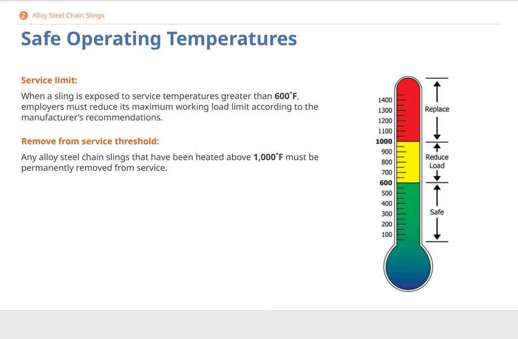
Safe Operating Temperatures Service limit:
When a sling is exposed to service temperatures greater than 600˚F, employers must reduce its maximum working load limit according to the manufacturer’s recommendations.
Remove from service threshold:
Any alloy steel chain slings that have been heated above 1,000˚F must be permanently removed from service. 2 Alloy Steel Chain Slings<br>
When a sling is exposed to service temperatures greater than 600˚F, employers must reduce its maximum working load limit according to the manufacturer’s recommendations.
Remove from service threshold:
Any alloy steel chain slings that have been heated above 1,000˚F must be permanently removed from service. 2 Alloy Steel Chain Slings<br>
55
Repair and Reconditioning Worn or damaged slings:
Worn or damaged alloy steel chain slings or attachments are not to be used until repaired. If welding or heat testing is performed, slings must also be reconditioned and proof-tested by the sling manufacturer or equivalent entity prior to re-entering service.
Broken chain:
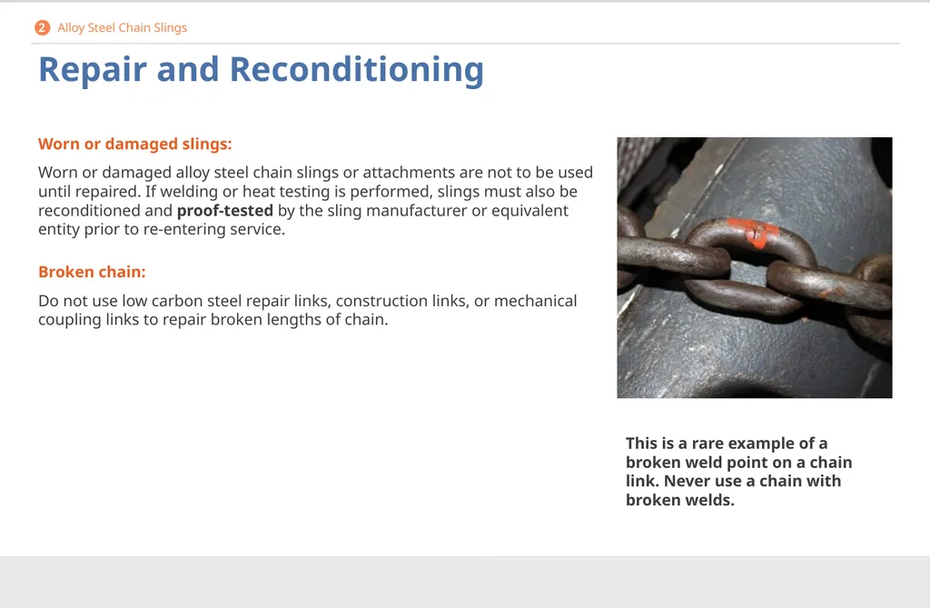
Do not use low carbon steel repair links, construction links, or mechanical coupling links to repair broken lengths of chain. This is a rare example of a broken weld point on a chain link. Never use a chain with broken welds. 2 Alloy Steel Chain Slings<br>
Worn or damaged alloy steel chain slings or attachments are not to be used until repaired. If welding or heat testing is performed, slings must also be reconditioned and proof-tested by the sling manufacturer or equivalent entity prior to re-entering service.
Broken chain:
Do not use low carbon steel repair links, construction links, or mechanical coupling links to repair broken lengths of chain. This is a rare example of a broken weld point on a chain link. Never use a chain with broken welds. 2 Alloy Steel Chain Slings<br>
56
Proof-Testing Testing before use:
Any new, repaired, or reconditioned alloy steel chain slings, including all welded components in the sling assembly, must be proof-tested before use by the sling manufacturer or equivalent entity.
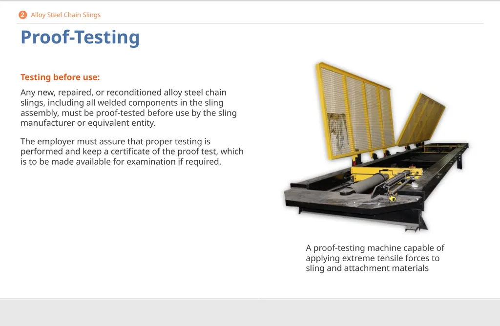
The employer must assure that proper testing is performed and keep a certificate of the proof test, which is to be made available for examination if required. A proof-testing machine capable of applying extreme tensile forces to sling and attachment materials 2 Alloy Steel Chain Slings<br>
Any new, repaired, or reconditioned alloy steel chain slings, including all welded components in the sling assembly, must be proof-tested before use by the sling manufacturer or equivalent entity.
The employer must assure that proper testing is performed and keep a certificate of the proof test, which is to be made available for examination if required. A proof-testing machine capable of applying extreme tensile forces to sling and attachment materials 2 Alloy Steel Chain Slings<br>
57
Effect of Wear Chains are prone to extreme wear during lifts.
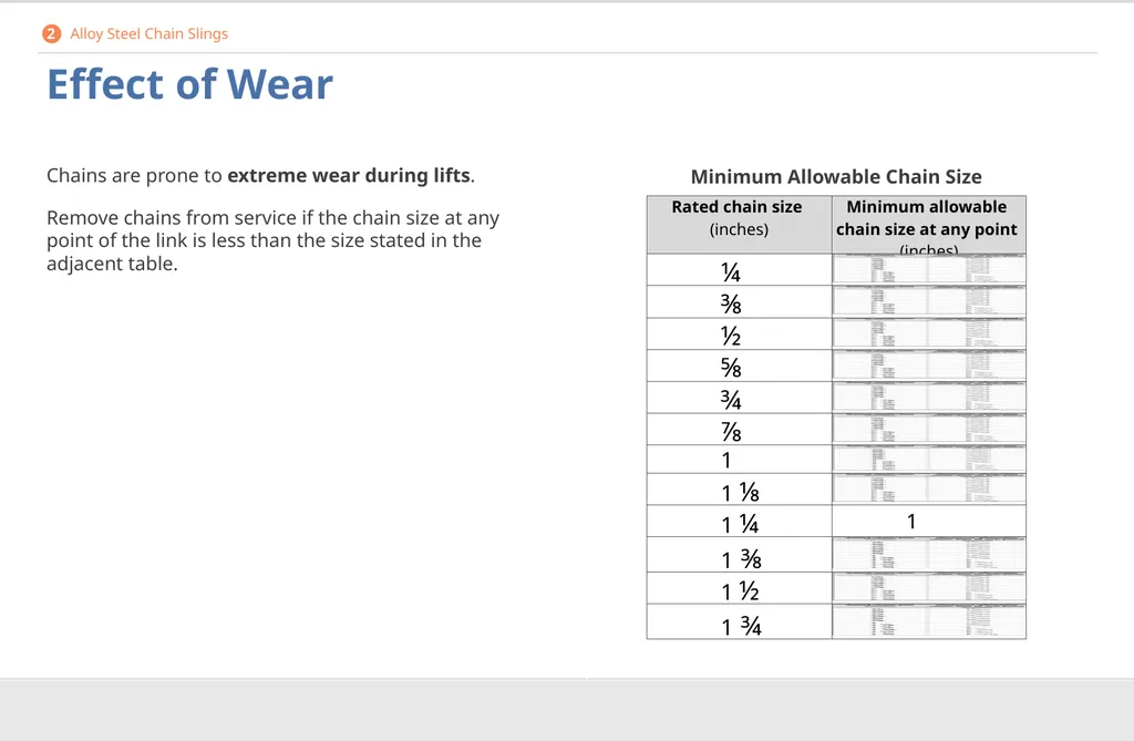
Remove chains from service if the chain size at any point of the link is less than the size stated in the adjacent table. Minimum Allowable Chain Size 2 Alloy Steel Chain Slings<br>
Remove chains from service if the chain size at any point of the link is less than the size stated in the adjacent table. Minimum Allowable Chain Size 2 Alloy Steel Chain Slings<br>
58
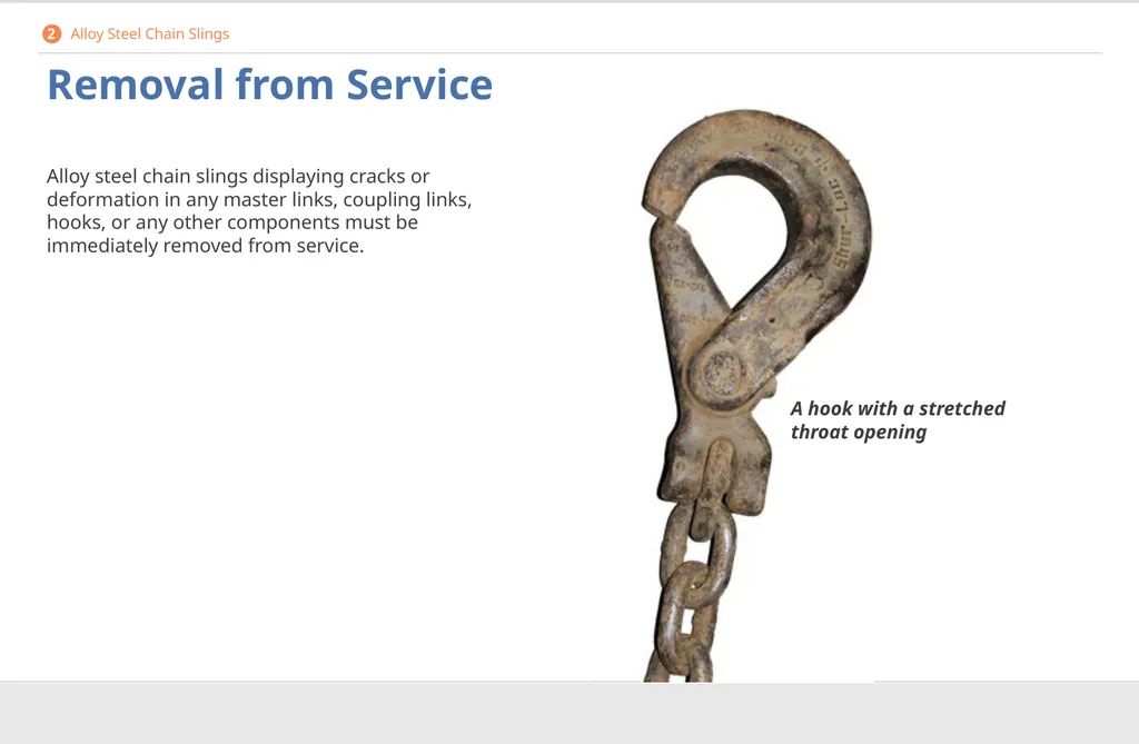
Removal from Service Alloy steel chain slings displaying cracks or deformation in any master links, coupling links, hooks, or any other components must be immediately removed from service. A hook with a stretched throat opening 2 Alloy Steel Chain Slings<br>
59
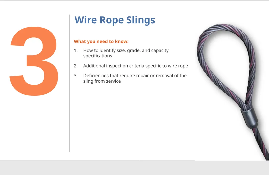
Wire Rope Slings What you need to know:
How to identify size, grade, and capacity specifications
Additional inspection criteria specific to wire rope
Deficiencies that require repair or removal of the sling from service 3<br>
How to identify size, grade, and capacity specifications
Additional inspection criteria specific to wire rope
Deficiencies that require repair or removal of the sling from service 3<br>
60
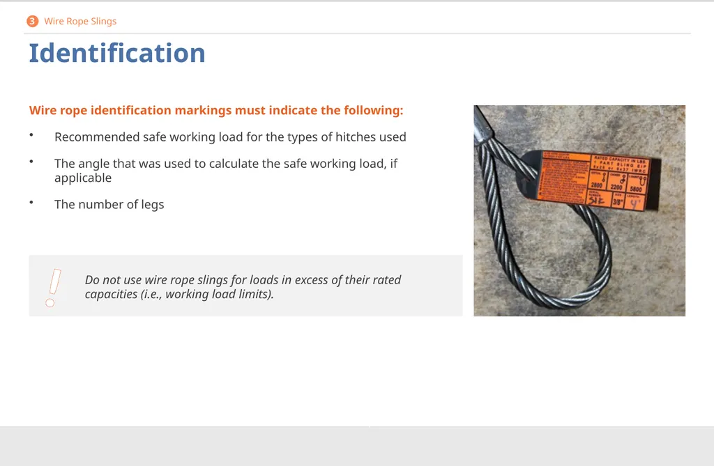
Identification Wire rope identification markings must indicate the following:
Recommended safe working load for the types of hitches used
The angle that was used to calculate the safe working load, if applicable
The number of legs 3 Wire Rope Slings ! Do not use wire rope slings for loads in excess of their rated capacities (i.e., working load limits).<br>
Recommended safe working load for the types of hitches used
The angle that was used to calculate the safe working load, if applicable
The number of legs 3 Wire Rope Slings ! Do not use wire rope slings for loads in excess of their rated capacities (i.e., working load limits).<br>
61
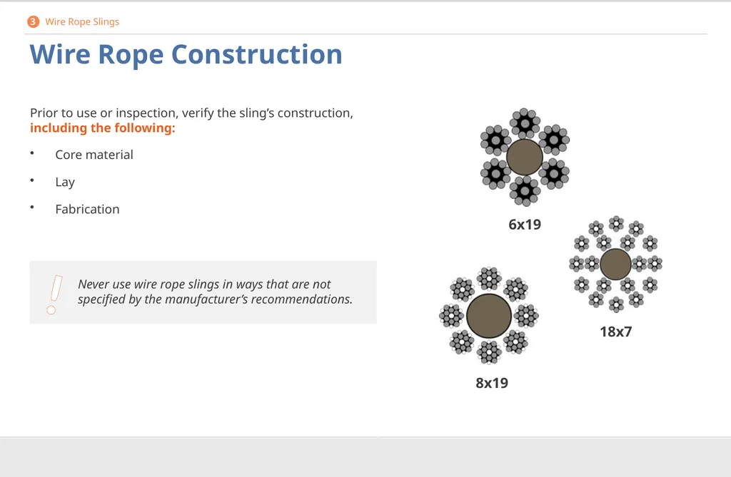
! Wire Rope Construction Prior to use or inspection, verify the sling’s construction, including the following:
Core material
Lay
Fabrication 6x19 8x19 18x7 3 Wire Rope Slings Never use wire rope slings in ways that are not specified by the manufacturer’s recommendations.<br>
Core material
Lay
Fabrication 6x19 8x19 18x7 3 Wire Rope Slings Never use wire rope slings in ways that are not specified by the manufacturer’s recommendations.<br>
62
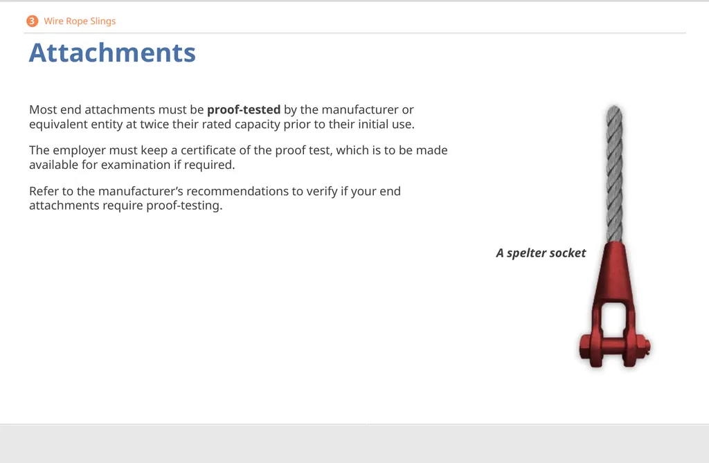
Attachments Most end attachments must be proof-tested by the manufacturer or equivalent entity at twice their rated capacity prior to their initial use.
The employer must keep a certificate of the proof test, which is to be made available for examination if required.
Refer to the manufacturer’s recommendations to verify if your end attachments require proof-testing. A spelter socket 3 Wire Rope Slings<br>
The employer must keep a certificate of the proof test, which is to be made available for examination if required.
Refer to the manufacturer’s recommendations to verify if your end attachments require proof-testing. A spelter socket 3 Wire Rope Slings<br>
63
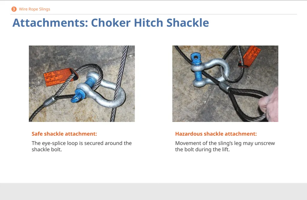
Attachments: Choker Hitch Shackle Safe shackle attachment:
The eye-splice loop is secured around the shackle bolt. Hazardous shackle attachment:
Movement of the sling’s leg may unscrew the bolt during the lift. 3 Wire Rope Slings<br>
The eye-splice loop is secured around the shackle bolt. Hazardous shackle attachment:
Movement of the sling’s leg may unscrew the bolt during the lift. 3 Wire Rope Slings<br>
64
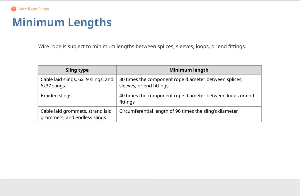
Minimum Lengths Wire rope is subject to minimum lengths between splices, sleeves, loops, or end fittings. 3 Wire Rope Slings<br>
65
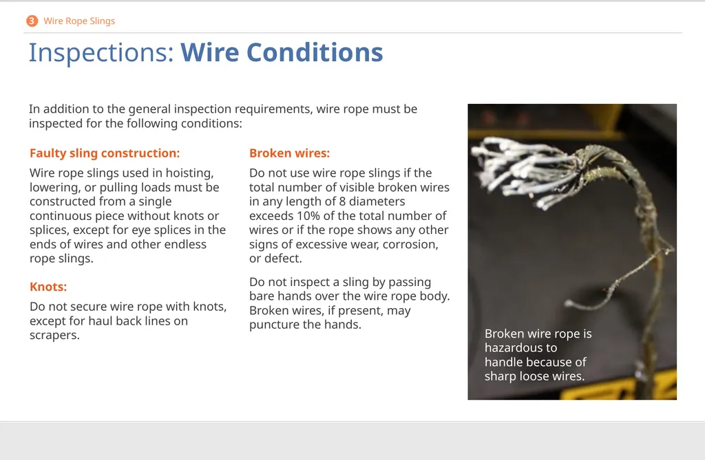
Inspections: Wire Conditions In addition to the general inspection requirements, wire rope must be inspected for the following conditions: Broken wire rope is hazardous to handle because of sharp loose wires. Faulty sling construction:
Wire rope slings used in hoisting, lowering, or pulling loads must be constructed from a single continuous piece without knots or splices, except for eye splices in the ends of wires and other endless rope slings.
Knots:
Do not secure wire rope with knots, except for haul back lines on scrapers. Broken wires:
Do not use wire rope slings if the total number of visible broken wires in any length of 8 diameters exceeds 10% of the total number of wires or if the rope shows any other signs of excessive wear, corrosion, or defect.
Do not inspect a sling by passing bare hands over the wire rope body. Broken wires, if present, may puncture the hands. 3 Wire Rope Slings<br>
Wire rope slings used in hoisting, lowering, or pulling loads must be constructed from a single continuous piece without knots or splices, except for eye splices in the ends of wires and other endless rope slings.
Knots:
Do not secure wire rope with knots, except for haul back lines on scrapers. Broken wires:
Do not use wire rope slings if the total number of visible broken wires in any length of 8 diameters exceeds 10% of the total number of wires or if the rope shows any other signs of excessive wear, corrosion, or defect.
Do not inspect a sling by passing bare hands over the wire rope body. Broken wires, if present, may puncture the hands. 3 Wire Rope Slings<br>
66
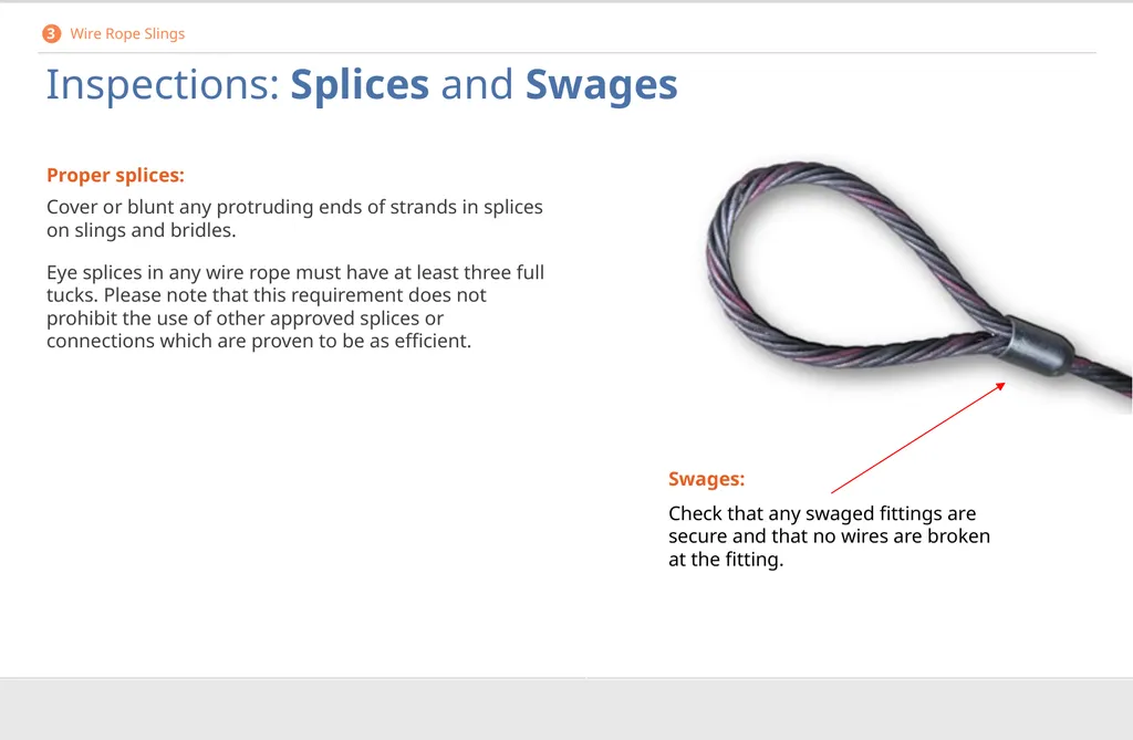
Inspections: Splices and Swages Proper splices:
Cover or blunt any protruding ends of strands in splices on slings and bridles.
Eye splices in any wire rope must have at least three full tucks. Please note that this requirement does not prohibit the use of other approved splices or connections which are proven to be as efficient. Swages:
Check that any swaged fittings are secure and that no wires are broken at the fitting. 3 Wire Rope Slings<br>
Cover or blunt any protruding ends of strands in splices on slings and bridles.
Eye splices in any wire rope must have at least three full tucks. Please note that this requirement does not prohibit the use of other approved splices or connections which are proven to be as efficient. Swages:
Check that any swaged fittings are secure and that no wires are broken at the fitting. 3 Wire Rope Slings<br>
67
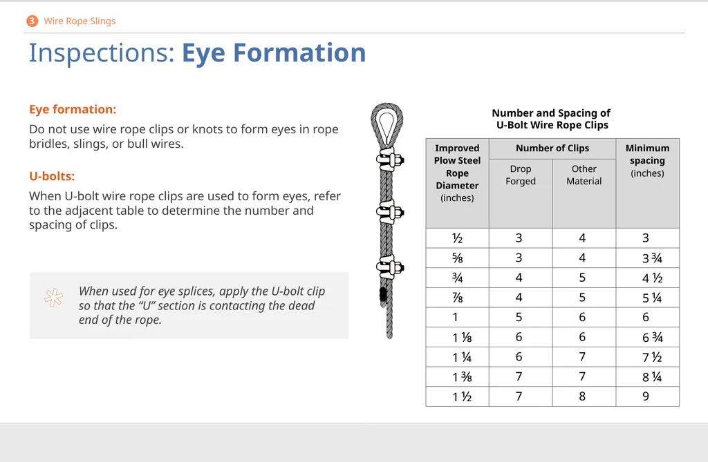
* Inspections: Eye Formation Eye formation:
Do not use wire rope clips or knots to form eyes in rope bridles, slings, or bull wires.
U-bolts:
When U-bolt wire rope clips are used to form eyes, refer to the adjacent table to determine the number and spacing of clips. Number and Spacing of U-Bolt Wire Rope Clips 3 Wire Rope Slings When used for eye splices, apply the U-bolt clip so that the “U” section is contacting the dead end of the rope.<br>
Do not use wire rope clips or knots to form eyes in rope bridles, slings, or bull wires.
U-bolts:
When U-bolt wire rope clips are used to form eyes, refer to the adjacent table to determine the number and spacing of clips. Number and Spacing of U-Bolt Wire Rope Clips 3 Wire Rope Slings When used for eye splices, apply the U-bolt clip so that the “U” section is contacting the dead end of the rope.<br>
68
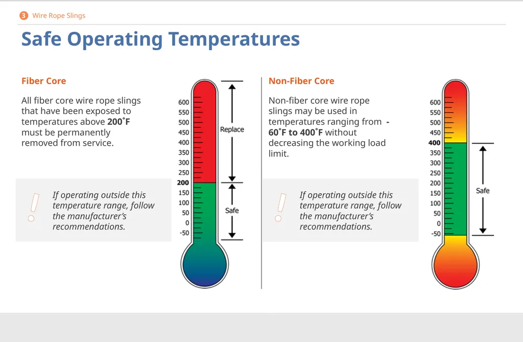
Safe Operating Temperatures Fiber Core
All fiber core wire rope slings that have been exposed to temperatures above 200˚F must be permanently removed from service. Non-Fiber Core
Non-fiber core wire rope slings may be used in temperatures ranging from -60˚F to 400˚F without decreasing the working load limit. 3 Wire Rope Slings ! If operating outside this temperature range, follow the manufacturer’s recommendations. ! If operating outside this temperature range, follow the manufacturer’s recommendations.<br>
All fiber core wire rope slings that have been exposed to temperatures above 200˚F must be permanently removed from service. Non-Fiber Core
Non-fiber core wire rope slings may be used in temperatures ranging from -60˚F to 400˚F without decreasing the working load limit. 3 Wire Rope Slings ! If operating outside this temperature range, follow the manufacturer’s recommendations. ! If operating outside this temperature range, follow the manufacturer’s recommendations.<br>
69
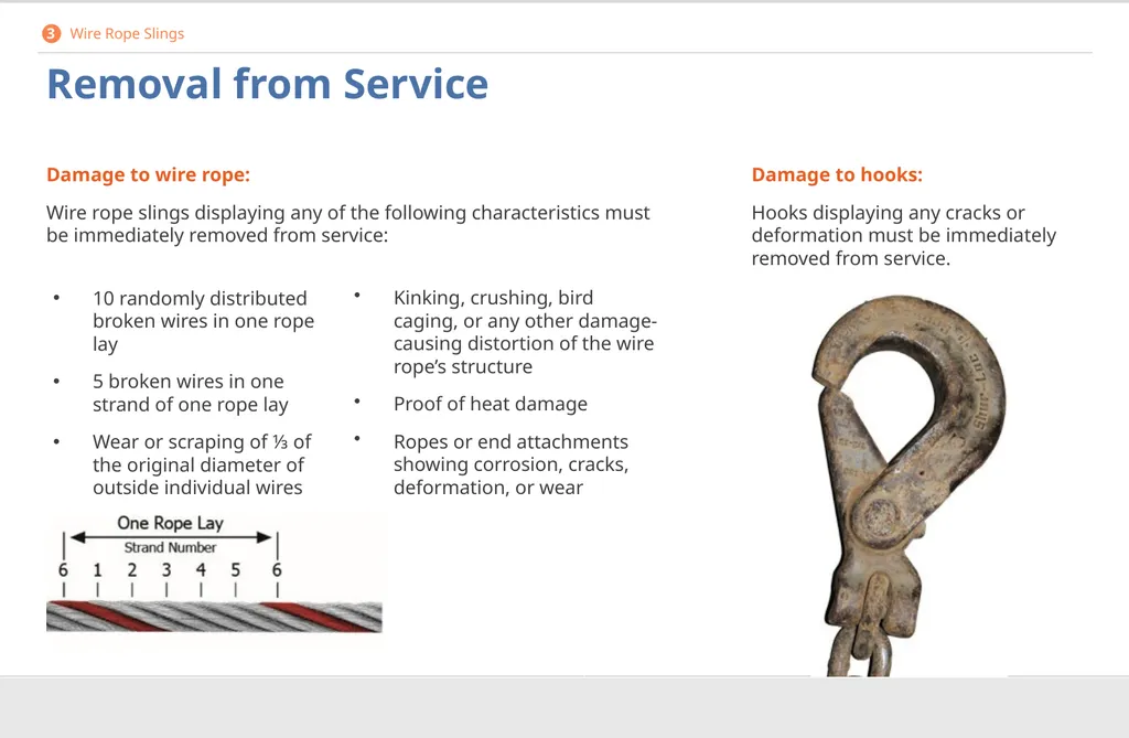
Removal from Service Damage to wire rope:
Wire rope slings displaying any of the following characteristics must be immediately removed from service: Damage to hooks:
Hooks displaying any cracks or deformation must be immediately removed from service. 3 Wire Rope Slings Kinking, crushing, bird caging, or any other damage-causing distortion of the wire rope’s structure
Proof of heat damage
Ropes or end attachments showing corrosion, cracks, deformation, or wear 10 randomly distributed broken wires in one rope lay
5 broken wires in one strand of one rope lay
Wear or scraping of ⅓ of the original diameter of outside individual wires<br>
Wire rope slings displaying any of the following characteristics must be immediately removed from service: Damage to hooks:
Hooks displaying any cracks or deformation must be immediately removed from service. 3 Wire Rope Slings Kinking, crushing, bird caging, or any other damage-causing distortion of the wire rope’s structure
Proof of heat damage
Ropes or end attachments showing corrosion, cracks, deformation, or wear 10 randomly distributed broken wires in one rope lay
5 broken wires in one strand of one rope lay
Wear or scraping of ⅓ of the original diameter of outside individual wires<br>
70
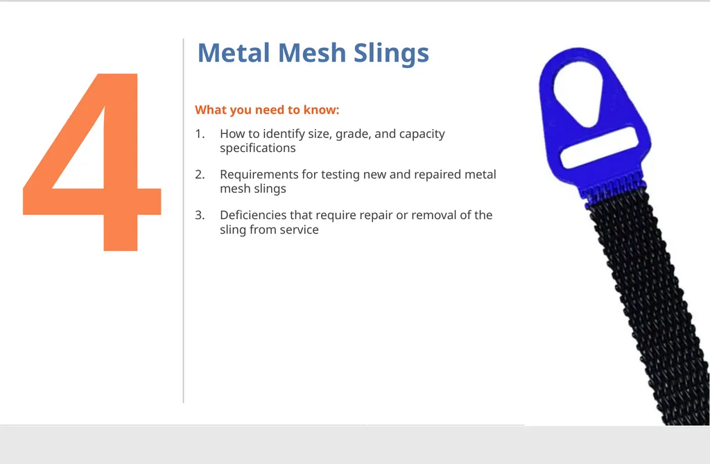
Metal Mesh Slings What you need to know:
How to identify size, grade, and capacity specifications
Requirements for testing new and repaired metal mesh slings
Deficiencies that require repair or removal of the sling from service 4<br>
How to identify size, grade, and capacity specifications
Requirements for testing new and repaired metal mesh slings
Deficiencies that require repair or removal of the sling from service 4<br>
71
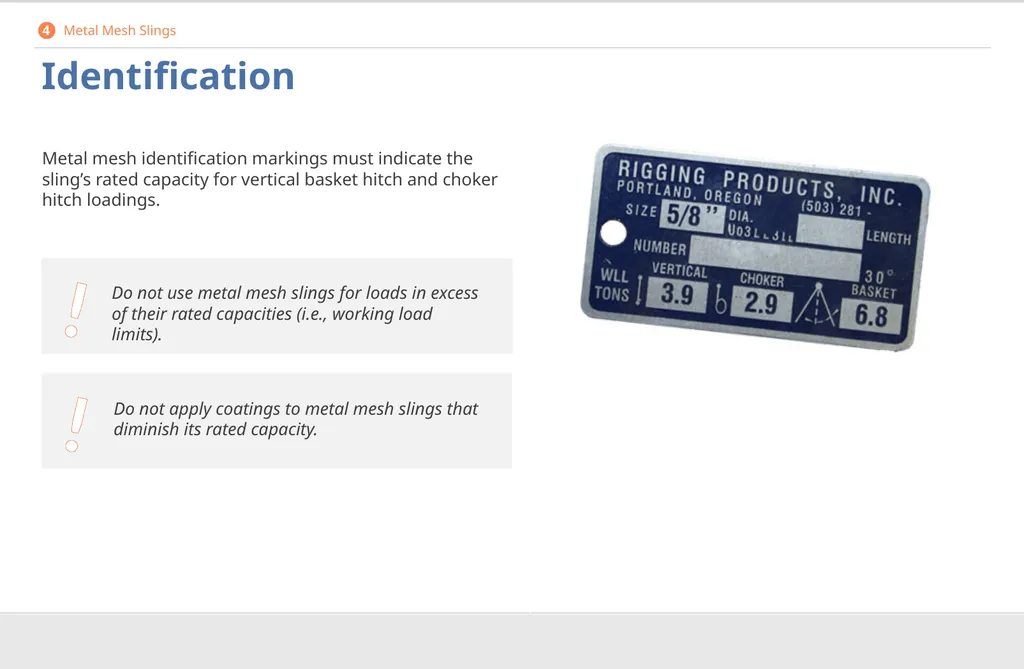
Identification Metal mesh identification markings must indicate the sling’s rated capacity for vertical basket hitch and choker hitch loadings. 4 Metal Mesh Slings ! Do not apply coatings to metal mesh slings that diminish its rated capacity. ! Do not use metal mesh slings for loads in excess of their rated capacities (i.e., working load limits).<br>
72
Attachments Handles or other attachments must have a rated capacity at least equal to that of the metal mesh sling and must not exhibit any deformation after proof-testing.
Make sure that:
Handles are attached to the sling in a way that does not reduce the sling’s rated capacity.
The load is evenly distributed across the width of the fabric.
Sharp edges do not damage the fabric.
All attachments are rated for the temperature in your lifting environment. 4 Metal Mesh Slings<br>
Make sure that:
Handles are attached to the sling in a way that does not reduce the sling’s rated capacity.
The load is evenly distributed across the width of the fabric.
Sharp edges do not damage the fabric.
All attachments are rated for the temperature in your lifting environment. 4 Metal Mesh Slings<br>
73
Repair and Reconditioning Manufacturer Repairs
Do not use repaired metal mesh slings unless the repairs were performed by the sling’s manufacturer or an equivalent entity.
Any repairs must be indicated either by permanently marking or tagging the sling or keeping a written record detailing the date and nature of the repairs and the person or organization that performed the repairs.
Any records are to be made available for examination if required. Manufacturer Proof-Testing Do not use any new or repaired metal mesh slings, including handles or other attachments, until they have been proof-tested by the manufacturer or equivalent entity to at least 1 ½ times their rated capacity.
Proof-testing must be performed on elastomer impregnated slings prior to coating. 4 Metal Mesh Slings<br>
Any repairs must be indicated either by permanently marking or tagging the sling or keeping a written record detailing the date and nature of the repairs and the person or organization that performed the repairs.
Any records are to be made available for examination if required. Manufacturer Proof-Testing Do not use any new or repaired metal mesh slings, including handles or other attachments, until they have been proof-tested by the manufacturer or equivalent entity to at least 1 ½ times their rated capacity.
Proof-testing must be performed on elastomer impregnated slings prior to coating. 4 Metal Mesh Slings<br>
74
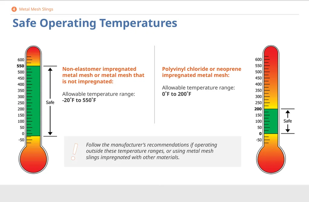
! Safe Operating Temperatures Follow the manufacturer’s recommendations if operating outside these temperature ranges, or using metal mesh slings impregnated with other materials. Non-elastomer impregnated metal mesh or metal mesh that is not impregnated:
Allowable temperature range:
-20˚F to 550˚F Polyvinyl chloride or neoprene impregnated metal mesh:
Allowable temperature range:
0˚F to 200˚F 4 Metal Mesh Slings<br>
75
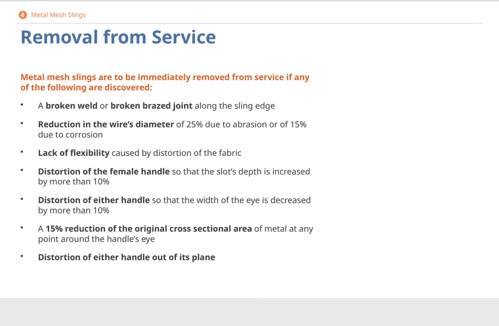
Removal from Service Metal mesh slings are to be immediately removed from service if any of the following are discovered:
A broken weld or broken brazed joint along the sling edge
Reduction in the wire’s diameter of 25% due to abrasion or of 15% due to corrosion
Lack of flexibility caused by distortion of the fabric
Distortion of the female handle so that the slot’s depth is increased by more than 10%
Distortion of either handle so that the width of the eye is decreased by more than 10%
A 15% reduction of the original cross sectional area of metal at any point around the handle’s eye
Distortion of either handle out of its plane 4 Metal Mesh Slings<br>
A broken weld or broken brazed joint along the sling edge
Reduction in the wire’s diameter of 25% due to abrasion or of 15% due to corrosion
Lack of flexibility caused by distortion of the fabric
Distortion of the female handle so that the slot’s depth is increased by more than 10%
Distortion of either handle so that the width of the eye is decreased by more than 10%
A 15% reduction of the original cross sectional area of metal at any point around the handle’s eye
Distortion of either handle out of its plane 4 Metal Mesh Slings<br>
76
Natural and Synthetic Fiber Rope What you need to know:
How to identify size, grade, and capacity specifications
Proper splicing requirements
Deficiencies that require repair or removal of the sling from service 5<br>
How to identify size, grade, and capacity specifications
Proper splicing requirements
Deficiencies that require repair or removal of the sling from service 5<br>
77
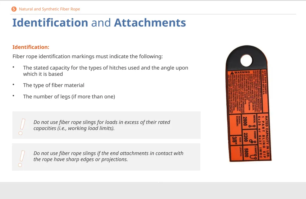
Identification and Attachments Identification:
Fiber rope identification markings must indicate the following:
The stated capacity for the types of hitches used and the angle upon which it is based
The type of fiber material
The number of legs (if more than one) 5 Natural and Synthetic Fiber Rope ! Do not use fiber rope slings for loads in excess of their rated capacities (i.e., working load limits). ! Do not use fiber rope slings if the end attachments in contact with the rope have sharp edges or projections.<br>
Fiber rope identification markings must indicate the following:
The stated capacity for the types of hitches used and the angle upon which it is based
The type of fiber material
The number of legs (if more than one) 5 Natural and Synthetic Fiber Rope ! Do not use fiber rope slings for loads in excess of their rated capacities (i.e., working load limits). ! Do not use fiber rope slings if the end attachments in contact with the rope have sharp edges or projections.<br>
78
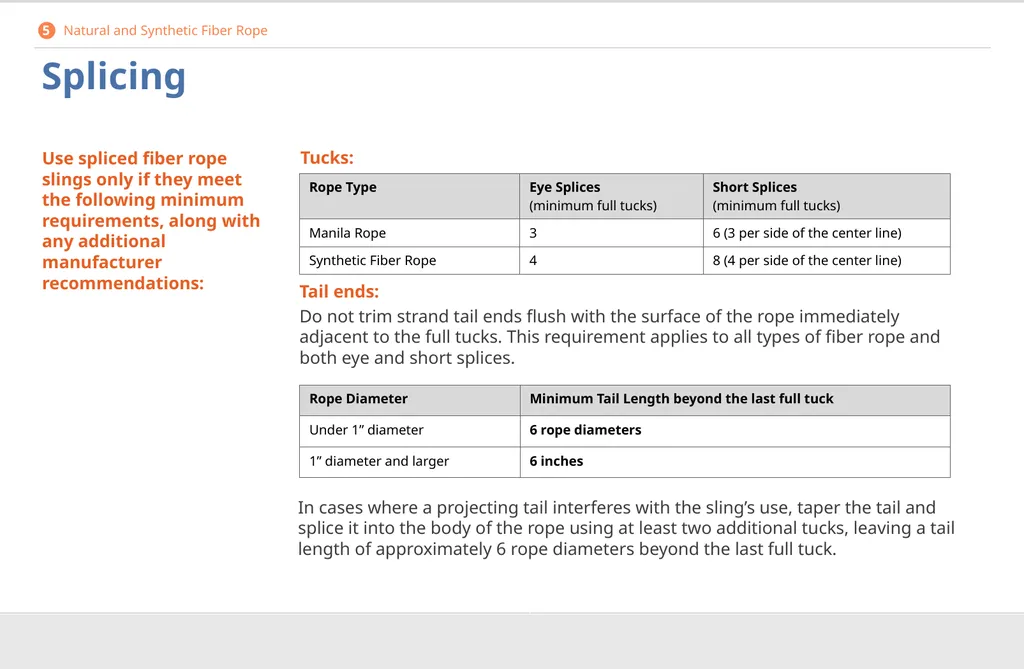
Splicing Use spliced fiber rope slings only if they meet the following minimum requirements, along with any additional manufacturer recommendations: In cases where a projecting tail interferes with the sling’s use, taper the tail and splice it into the body of the rope using at least two additional tucks, leaving a tail length of approximately 6 rope diameters beyond the last full tuck. Tail ends:
Do not trim strand tail ends flush with the surface of the rope immediately adjacent to the full tucks. This requirement applies to all types of fiber rope and both eye and short splices. Tucks: 5 Natural and Synthetic Fiber Rope<br>
Do not trim strand tail ends flush with the surface of the rope immediately adjacent to the full tucks. This requirement applies to all types of fiber rope and both eye and short splices. Tucks: 5 Natural and Synthetic Fiber Rope<br>
79
Splicing Minimum clear length:
The required minimum clear length of rope between eye splices is equal to 10 times the rope’s diameter.
Knots:
Do not use knots in place of splices.
Specialized clamps:
Only use clamps specifically designed for fiber ropes and splicing.
Proper splice sizing:
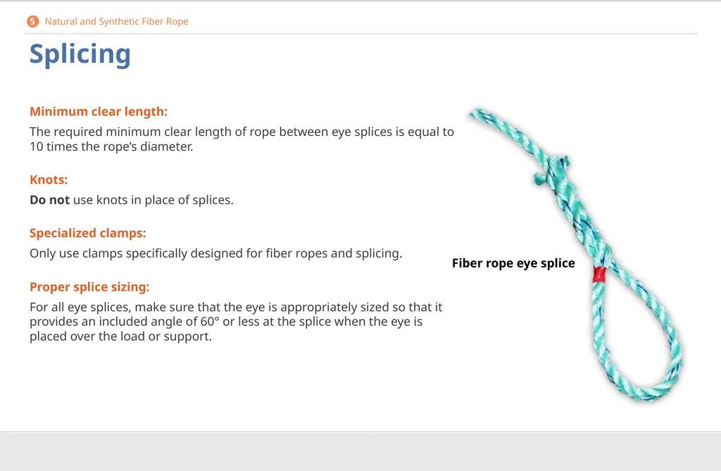
For all eye splices, make sure that the eye is appropriately sized so that it provides an included angle of 60° or less at the splice when the eye is placed over the load or support. Fiber rope eye splice 5 Natural and Synthetic Fiber Rope<br>
The required minimum clear length of rope between eye splices is equal to 10 times the rope’s diameter.
Knots:
Do not use knots in place of splices.
Specialized clamps:
Only use clamps specifically designed for fiber ropes and splicing.
Proper splice sizing:
For all eye splices, make sure that the eye is appropriately sized so that it provides an included angle of 60° or less at the splice when the eye is placed over the load or support. Fiber rope eye splice 5 Natural and Synthetic Fiber Rope<br>
80
Safe Operating Temperatures and Repairs Safe Operating Temperatures
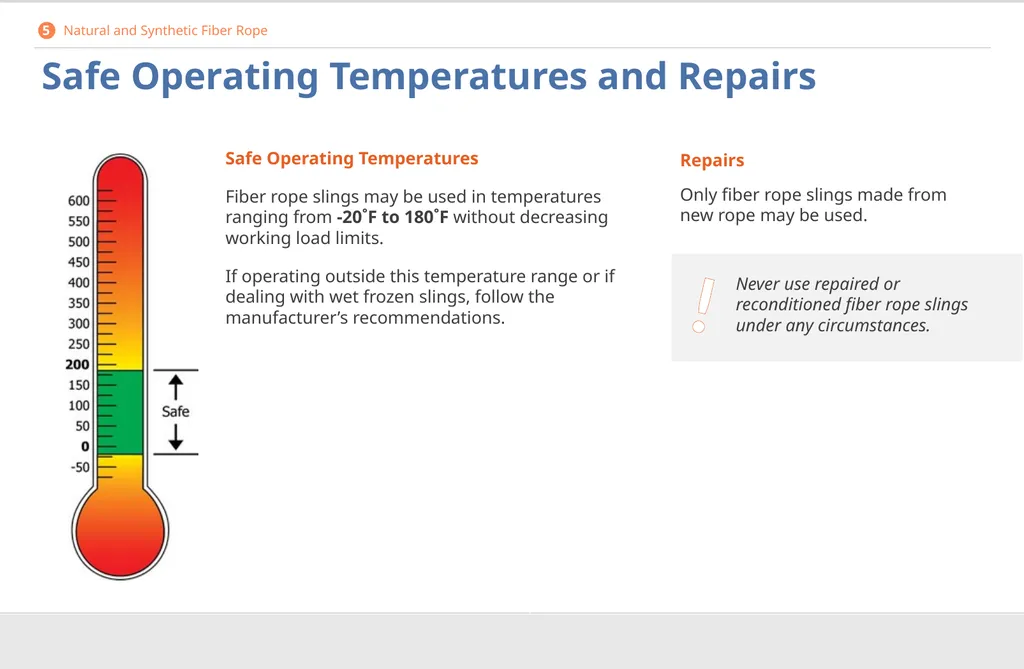
Fiber rope slings may be used in temperatures ranging from -20˚F to 180˚F without decreasing working load limits.
If operating outside this temperature range or if dealing with wet frozen slings, follow the manufacturer’s recommendations. Repairs
Only fiber rope slings made from new rope may be used. 5 Natural and Synthetic Fiber Rope ! Never use repaired or reconditioned fiber rope slings under any circumstances.<br>
Fiber rope slings may be used in temperatures ranging from -20˚F to 180˚F without decreasing working load limits.
If operating outside this temperature range or if dealing with wet frozen slings, follow the manufacturer’s recommendations. Repairs
Only fiber rope slings made from new rope may be used. 5 Natural and Synthetic Fiber Rope ! Never use repaired or reconditioned fiber rope slings under any circumstances.<br>
81
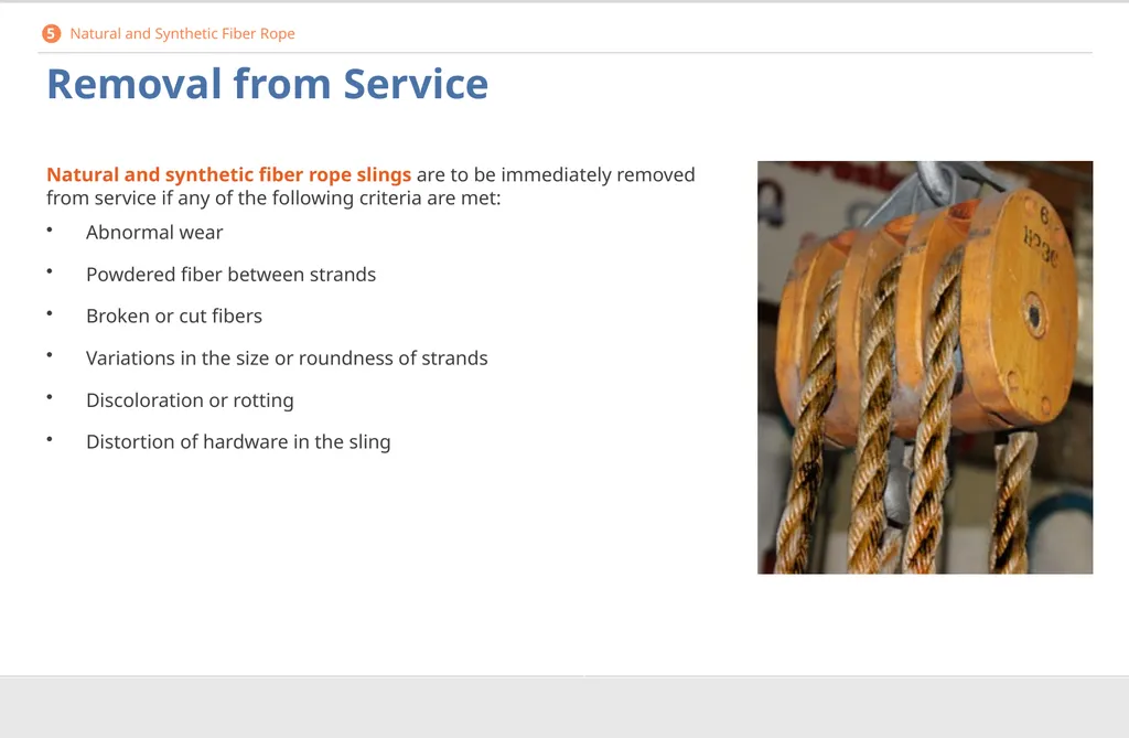
Removal from Service Natural and synthetic fiber rope slings are to be immediately removed from service if any of the following criteria are met:
Abnormal wear
Powdered fiber between strands
Broken or cut fibers
Variations in the size or roundness of strands
Discoloration or rotting
Distortion of hardware in the sling 5 Natural and Synthetic Fiber Rope<br>
Abnormal wear
Powdered fiber between strands
Broken or cut fibers
Variations in the size or roundness of strands
Discoloration or rotting
Distortion of hardware in the sling 5 Natural and Synthetic Fiber Rope<br>
82
Synthetic Web Slings What you need to know:
How to identify size, grade, and capacity specifications
Necessary precautions to be taken in specific environmental conditions
Deficiencies that require repair or removal of the sling from service 6<br>
How to identify size, grade, and capacity specifications
Necessary precautions to be taken in specific environmental conditions
Deficiencies that require repair or removal of the sling from service 6<br>
83
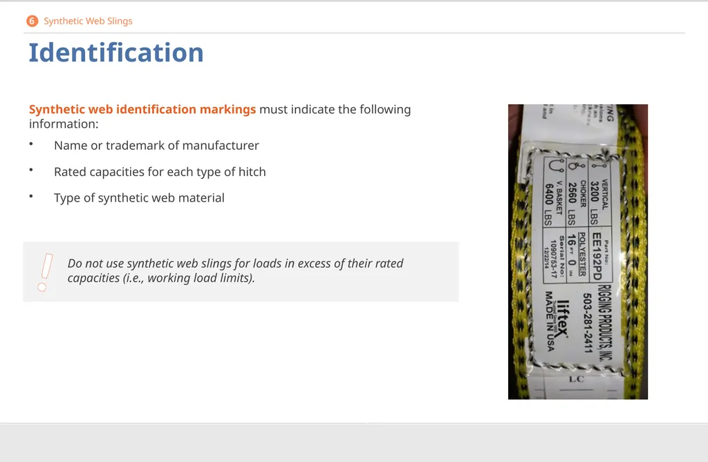
Identification Synthetic web identification markings must indicate the following information:
Name or trademark of manufacturer
Rated capacities for each type of hitch
Type of synthetic web material 6 Synthetic Web Slings ! Do not use synthetic web slings for loads in excess of their rated capacities (i.e., working load limits).<br>
Name or trademark of manufacturer
Rated capacities for each type of hitch
Type of synthetic web material 6 Synthetic Web Slings ! Do not use synthetic web slings for loads in excess of their rated capacities (i.e., working load limits).<br>
84
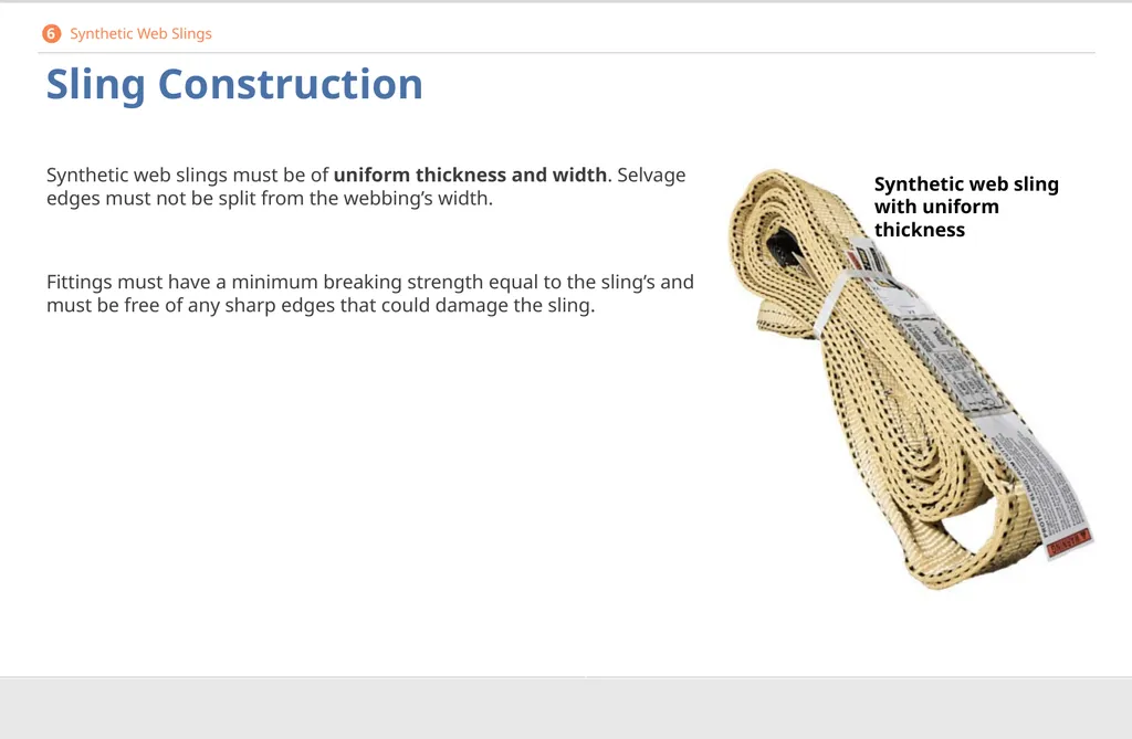
Sling Construction Synthetic web slings must be of uniform thickness and width. Selvage edges must not be split from the webbing’s width.
Fittings must have a minimum breaking strength equal to the sling’s and must be free of any sharp edges that could damage the sling. Synthetic web sling with uniform thickness 6 Synthetic Web Slings<br>
Fittings must have a minimum breaking strength equal to the sling’s and must be free of any sharp edges that could damage the sling. Synthetic web sling with uniform thickness 6 Synthetic Web Slings<br>
85
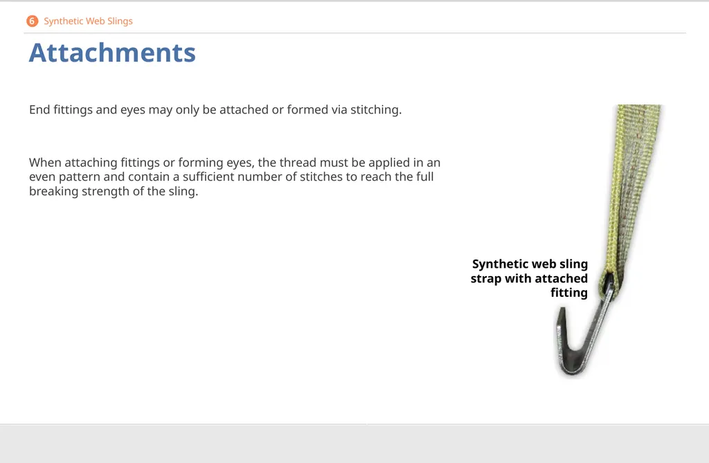
Attachments End fittings and eyes may only be attached or formed via stitching.
When attaching fittings or forming eyes, the thread must be applied in an even pattern and contain a sufficient number of stitches to reach the full breaking strength of the sling. Synthetic web sling strap with attached fitting 6 Synthetic Web Slings<br>
When attaching fittings or forming eyes, the thread must be applied in an even pattern and contain a sufficient number of stitches to reach the full breaking strength of the sling. Synthetic web sling strap with attached fitting 6 Synthetic Web Slings<br>
86
Environmental Conditions Certain synthetic web slings may not be used if specific environmental conditions are present.
Nylon web slings are not to be used where fumes, vapors, sprays, mists, or liquids of acids or phenols are present.
Polyester and polypropylene web slings, or any sling with aluminum fittings, are not to be used where fumes, vapors, sprays, mists, or liquids of caustics are present. 6 Synthetic Web Slings<br>
Nylon web slings are not to be used where fumes, vapors, sprays, mists, or liquids of acids or phenols are present.
Polyester and polypropylene web slings, or any sling with aluminum fittings, are not to be used where fumes, vapors, sprays, mists, or liquids of caustics are present. 6 Synthetic Web Slings<br>
87
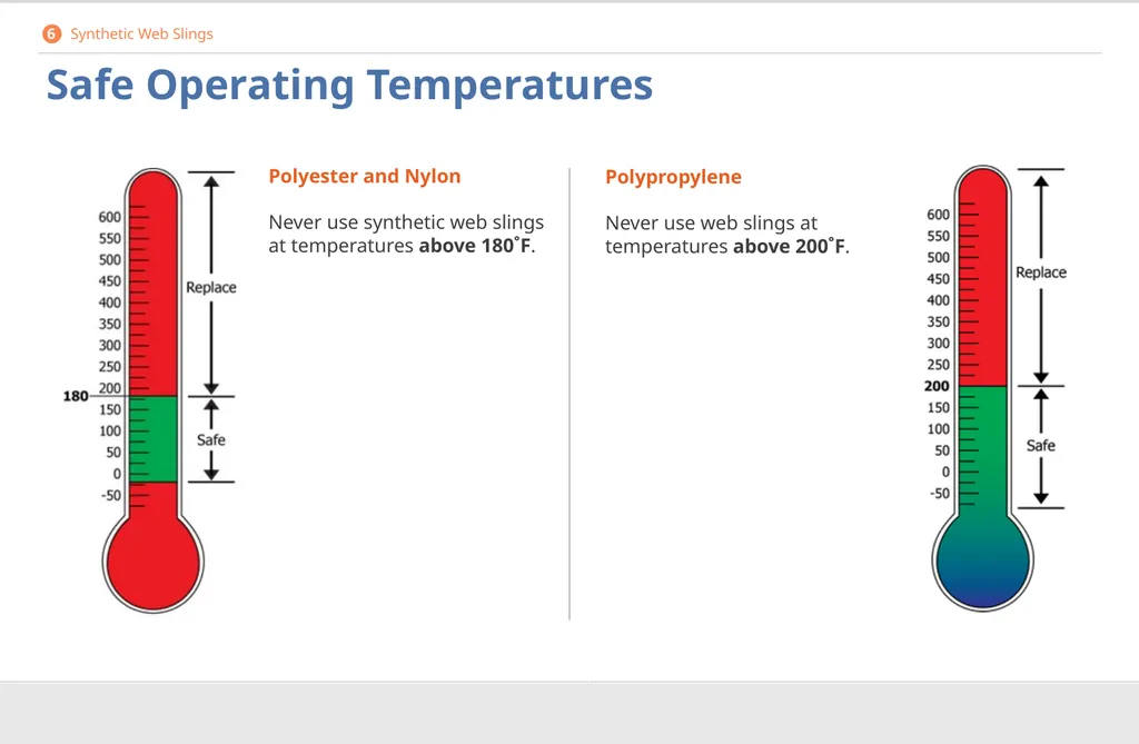
Safe Operating Temperatures Polyester and Nylon
Never use synthetic web slings at temperatures above 180˚F. Polypropylene
Never use web slings at temperatures above 200˚F. 6 Synthetic Web Slings<br>
88
Repairs Do not use repaired synthetic web slings if any part of the sling (including webbing and fittings) has been repaired in a temporary manner.
Only use repaired synthetic web slings if the repairs were performed by the sling manufacturer or equivalent entity.
In addition, all repaired slings must be proof-tested by the manufacturer or equivalent entity to twice its rated capacity before returning to service. The employer must keep a certificate of the proof test, which is to be made available for examination if required. 6 Synthetic Web Slings<br>
Only use repaired synthetic web slings if the repairs were performed by the sling manufacturer or equivalent entity.
In addition, all repaired slings must be proof-tested by the manufacturer or equivalent entity to twice its rated capacity before returning to service. The employer must keep a certificate of the proof test, which is to be made available for examination if required. 6 Synthetic Web Slings<br>
89
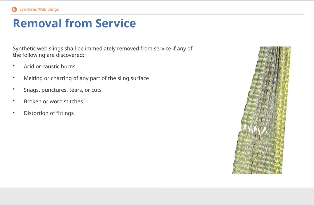
Removal from Service Synthetic web slings shall be immediately removed from service if any of the following are discovered:
Acid or caustic burns
Melting or charring of any part of the sling surface
Snags, punctures, tears, or cuts
Broken or worn stitches
Distortion of fittings 6 Synthetic Web Slings<br>
Acid or caustic burns
Melting or charring of any part of the sling surface
Snags, punctures, tears, or cuts
Broken or worn stitches
Distortion of fittings 6 Synthetic Web Slings<br>
90
Steel Erection Rigging What you need to know:
Pre-shift inspection requirements for cranes and rigging
Basic safety requirements during crane operations
Additional safe practices in specific scenarios 7<br>
Pre-shift inspection requirements for cranes and rigging
Basic safety requirements during crane operations
Additional safe practices in specific scenarios 7<br>
91
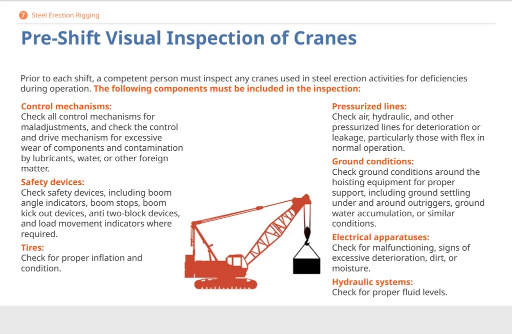
Pre-Shift Visual Inspection of Cranes Control mechanisms:
Check all control mechanisms for maladjustments, and check the control and drive mechanism for excessive wear of components and contamination by lubricants, water, or other foreign matter.
Safety devices: Check safety devices, including boom angle indicators, boom stops, boom kick out devices, anti two-block devices, and load movement indicators where required.
Tires: Check for proper inflation and condition. Pressurized lines: Check air, hydraulic, and other pressurized lines for deterioration or leakage, particularly those with flex in normal operation.
Ground conditions: Check ground conditions around the hoisting equipment for proper support, including ground settling under and around outriggers, ground water accumulation, or similar conditions.
Electrical apparatuses: Check for malfunctioning, signs of excessive deterioration, dirt, or moisture.
Hydraulic systems: Check for proper fluid levels. Prior to each shift, a competent person must inspect any cranes used in steel erection activities for deficiencies during operation. The following components must be included in the inspection: 7 Steel Erection Rigging<br>
Safety devices: Check safety devices, including boom angle indicators, boom stops, boom kick out devices, anti two-block devices, and load movement indicators where required.
Tires: Check for proper inflation and condition. Pressurized lines: Check air, hydraulic, and other pressurized lines for deterioration or leakage, particularly those with flex in normal operation.
Ground conditions: Check ground conditions around the hoisting equipment for proper support, including ground settling under and around outriggers, ground water accumulation, or similar conditions.
Electrical apparatuses: Check for malfunctioning, signs of excessive deterioration, dirt, or moisture.
Hydraulic systems: Check for proper fluid levels. Prior to each shift, a competent person must inspect any cranes used in steel erection activities for deficiencies during operation. The following components must be included in the inspection: 7 Steel Erection Rigging<br>
92
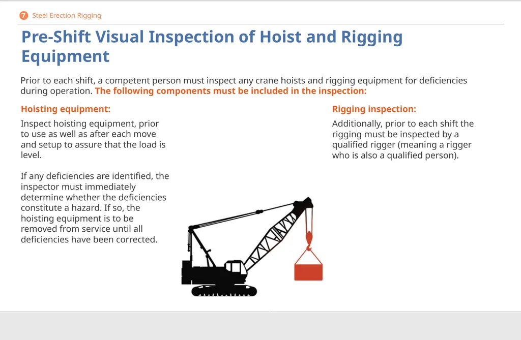
Pre-Shift Visual Inspection of Hoist and Rigging Equipment Rigging inspection:
Additionally, prior to each shift the rigging must be inspected by a qualified rigger (meaning a rigger who is also a qualified person). Hoisting equipment:
Inspect hoisting equipment, prior to use as well as after each move and setup to assure that the load is level.
If any deficiencies are identified, the inspector must immediately determine whether the deficiencies constitute a hazard. If so, the hoisting equipment is to be removed from service until all deficiencies have been corrected. Prior to each shift, a competent person must inspect any crane hoists and rigging equipment for deficiencies during operation. The following components must be included in the inspection: 7 Steel Erection Rigging<br>
Additionally, prior to each shift the rigging must be inspected by a qualified rigger (meaning a rigger who is also a qualified person). Hoisting equipment:
Inspect hoisting equipment, prior to use as well as after each move and setup to assure that the load is level.
If any deficiencies are identified, the inspector must immediately determine whether the deficiencies constitute a hazard. If so, the hoisting equipment is to be removed from service until all deficiencies have been corrected. Prior to each shift, a competent person must inspect any crane hoists and rigging equipment for deficiencies during operation. The following components must be included in the inspection: 7 Steel Erection Rigging<br>
93
Operation Operator control:
Licensed operators are responsible for all operations under their direct control. If concerns regarding safety arise, operators are authorized to stop and refuse to handle loads until safety has been assured.
Hoist riding:
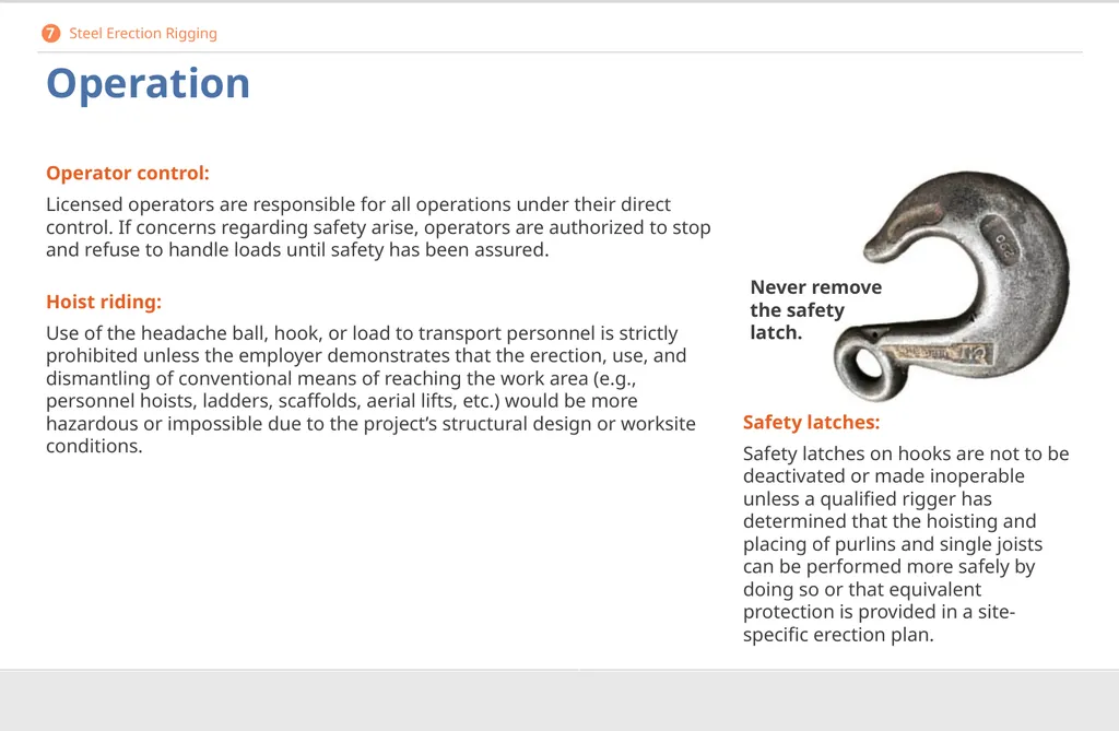
Use of the headache ball, hook, or load to transport personnel is strictly prohibited unless the employer demonstrates that the erection, use, and dismantling of conventional means of reaching the work area (e.g., personnel hoists, ladders, scaffolds, aerial lifts, etc.) would be more hazardous or impossible due to the project’s structural design or worksite conditions. Safety latches:
Safety latches on hooks are not to be deactivated or made inoperable unless a qualified rigger has determined that the hoisting and placing of purlins and single joists can be performed more safely by doing so or that equivalent protection is provided in a site-specific erection plan. Never remove the safety latch. 7 Steel Erection Rigging<br>
Licensed operators are responsible for all operations under their direct control. If concerns regarding safety arise, operators are authorized to stop and refuse to handle loads until safety has been assured.
Hoist riding:
Use of the headache ball, hook, or load to transport personnel is strictly prohibited unless the employer demonstrates that the erection, use, and dismantling of conventional means of reaching the work area (e.g., personnel hoists, ladders, scaffolds, aerial lifts, etc.) would be more hazardous or impossible due to the project’s structural design or worksite conditions. Safety latches:
Safety latches on hooks are not to be deactivated or made inoperable unless a qualified rigger has determined that the hoisting and placing of purlins and single joists can be performed more safely by doing so or that equivalent protection is provided in a site-specific erection plan. Never remove the safety latch. 7 Steel Erection Rigging<br>
94
Working Under Loads Pre-plan your routes.
Organize routes for suspended loads to assure that no employees are required to work directly below a suspended load, except for employees who are necessary for the initial connection, hooking, or unhooking of the load.
When working under suspended loads is necessary, the following conditions must be met:
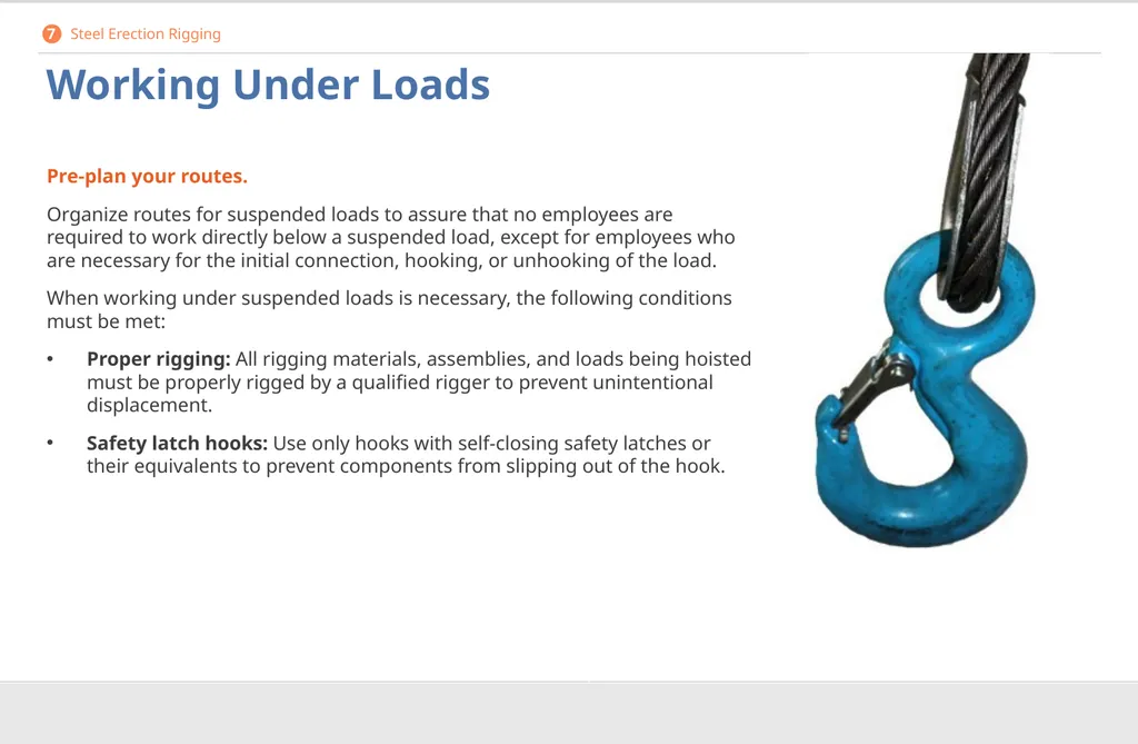
Proper rigging: All rigging materials, assemblies, and loads being hoisted must be properly rigged by a qualified rigger to prevent unintentional displacement.
Safety latch hooks: Use only hooks with self-closing safety latches or their equivalents to prevent components from slipping out of the hook. 7 Steel Erection Rigging<br>
Organize routes for suspended loads to assure that no employees are required to work directly below a suspended load, except for employees who are necessary for the initial connection, hooking, or unhooking of the load.
When working under suspended loads is necessary, the following conditions must be met:
Proper rigging: All rigging materials, assemblies, and loads being hoisted must be properly rigged by a qualified rigger to prevent unintentional displacement.
Safety latch hooks: Use only hooks with self-closing safety latches or their equivalents to prevent components from slipping out of the hook. 7 Steel Erection Rigging<br>
95
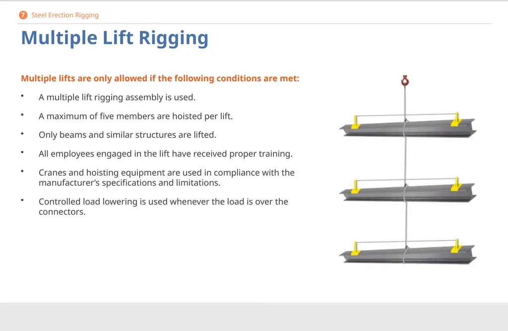
Multiple Lift Rigging Multiple lifts are only allowed if the following conditions are met:
A multiple lift rigging assembly is used.
A maximum of five members are hoisted per lift.
Only beams and similar structures are lifted.
All employees engaged in the lift have received proper training.
Cranes and hoisting equipment are used in compliance with the manufacturer’s specifications and limitations.
Controlled load lowering is used whenever the load is over the connectors. 7 Steel Erection Rigging<br>
A multiple lift rigging assembly is used.
A maximum of five members are hoisted per lift.
Only beams and similar structures are lifted.
All employees engaged in the lift have received proper training.
Cranes and hoisting equipment are used in compliance with the manufacturer’s specifications and limitations.
Controlled load lowering is used whenever the load is over the connectors. 7 Steel Erection Rigging<br>
96
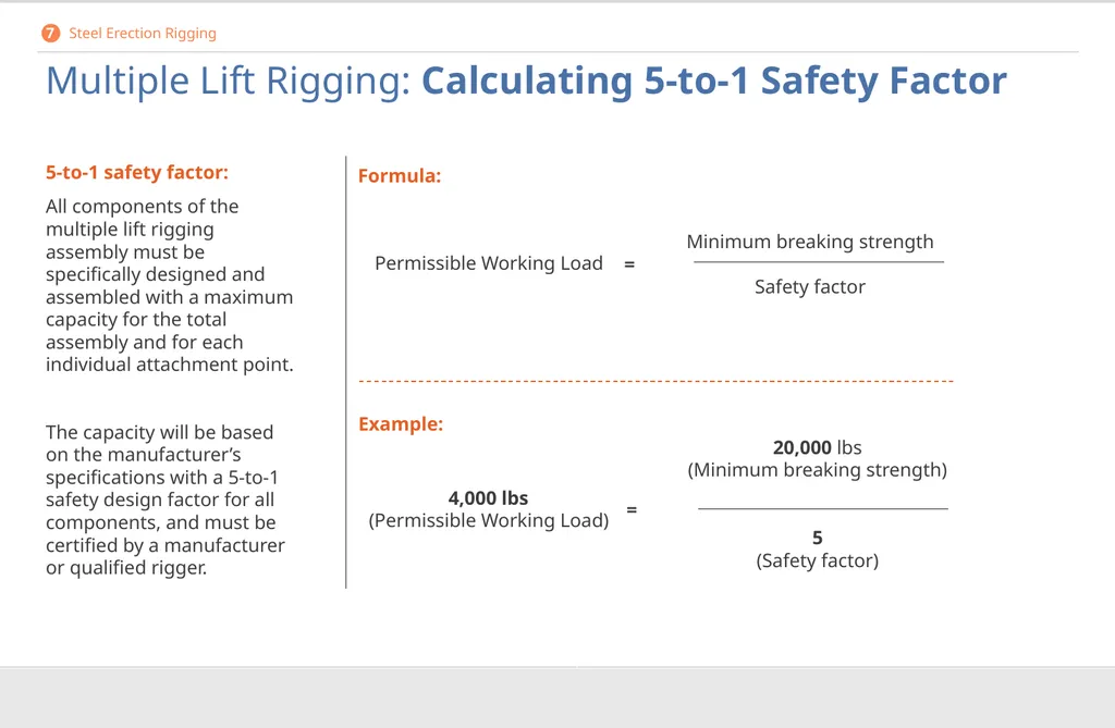
Multiple Lift Rigging: Calculating 5-to-1 Safety Factor 5-to-1 safety factor:
All components of the multiple lift rigging assembly must be specifically designed and assembled with a maximum capacity for the total assembly and for each individual attachment point. The capacity will be based on the manufacturer’s specifications with a 5-to-1 safety design factor for all components, and must be certified by a manufacturer or qualified rigger. Minimum breaking strength
Safety factor Permissible Working Load Formula: Example: 20,000 lbs (Minimum breaking strength)
5
(Safety factor) = 4,000 lbs
(Permissible Working Load) = 7 Steel Erection Rigging<br>
All components of the multiple lift rigging assembly must be specifically designed and assembled with a maximum capacity for the total assembly and for each individual attachment point. The capacity will be based on the manufacturer’s specifications with a 5-to-1 safety design factor for all components, and must be certified by a manufacturer or qualified rigger. Minimum breaking strength
Safety factor Permissible Working Load Formula: Example: 20,000 lbs (Minimum breaking strength)
5
(Safety factor) = 4,000 lbs
(Permissible Working Load) = 7 Steel Erection Rigging<br>
97
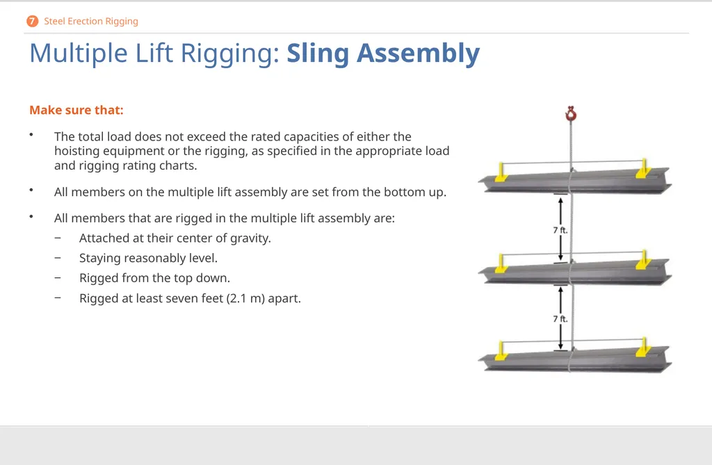
Multiple Lift Rigging: Sling Assembly Make sure that:
The total load does not exceed the rated capacities of either the hoisting equipment or the rigging, as specified in the appropriate load and rigging rating charts.
All members on the multiple lift assembly are set from the bottom up.
All members that are rigged in the multiple lift assembly are:
Attached at their center of gravity.
Staying reasonably level.
Rigged from the top down.
Rigged at least seven feet (2.1 m) apart. 7 Steel Erection Rigging<br>
The total load does not exceed the rated capacities of either the hoisting equipment or the rigging, as specified in the appropriate load and rigging rating charts.
All members on the multiple lift assembly are set from the bottom up.
All members that are rigged in the multiple lift assembly are:
Attached at their center of gravity.
Staying reasonably level.
Rigged from the top down.
Rigged at least seven feet (2.1 m) apart. 7 Steel Erection Rigging<br>
98
Hand Signals What you need to know:
How to recognize and perform standard hand signals for crane direction 8<br>
How to recognize and perform standard hand signals for crane direction 8<br>
99
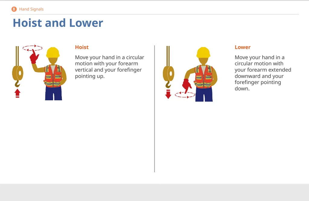
Hoist and Lower Hoist
Move your hand in a circular motion with your forearm vertical and your forefinger pointing up. Lower
Move your hand in a circular motion with your forearm extended downward and your forefinger pointing down. 8 Hand Signals<br>
Move your hand in a circular motion with your forearm vertical and your forefinger pointing up. Lower
Move your hand in a circular motion with your forearm extended downward and your forefinger pointing down. 8 Hand Signals<br>
100
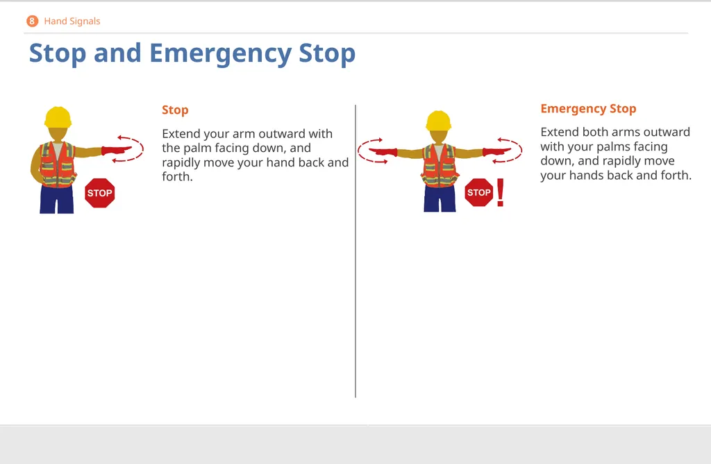
Stop and Emergency Stop Stop
Extend your arm outward with the palm facing down, and rapidly move your hand back and forth. Emergency Stop
Extend both arms outward with your palms facing down, and rapidly move your hands back and forth. 8 Hand Signals<br>
Extend your arm outward with the palm facing down, and rapidly move your hand back and forth. Emergency Stop
Extend both arms outward with your palms facing down, and rapidly move your hands back and forth. 8 Hand Signals<br>
101
Trolley Travel and Tower Travel Trolley Travel
Raise your hand with the palm facing up, the fingers closed, and the thumb pointing in the direction of travel. Tower Travel
Extend your arm forward with the hand open and slightly raised, and make a pushing motion in the direction of travel. 8 Hand Signals<br>
Raise your hand with the palm facing up, the fingers closed, and the thumb pointing in the direction of travel. Tower Travel
Extend your arm forward with the hand open and slightly raised, and make a pushing motion in the direction of travel. 8 Hand Signals<br>
102
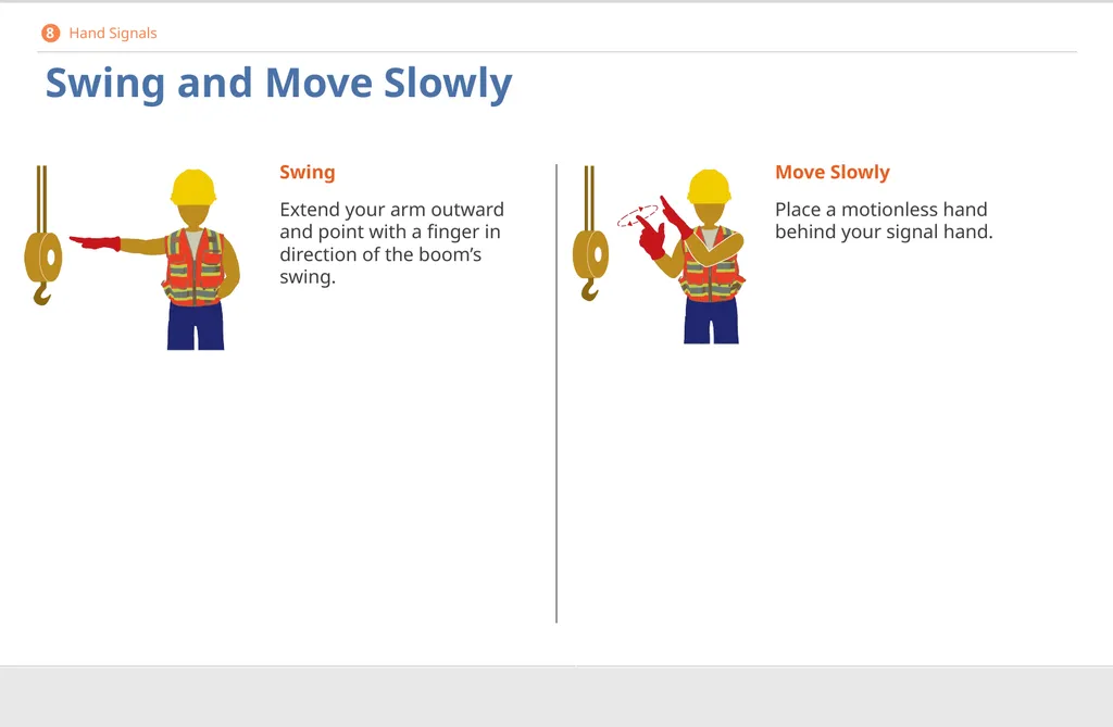
Swing and Move Slowly Swing
Extend your arm outward and point with a finger in direction of the boom’s swing. Move Slowly
Place a motionless hand behind your signal hand. 8 Hand Signals<br>
Extend your arm outward and point with a finger in direction of the boom’s swing. Move Slowly
Place a motionless hand behind your signal hand. 8 Hand Signals<br>
103
Dog Everything Dog (Hold) Everything
Clasp hands in front of your body. 8 Hand Signals<br>
Clasp hands in front of your body. 8 Hand Signals<br>