
Efficacious verification of Loopback and
LV
Published · 36 slides · 0 views
1 / 1
Description
Efficacious verification of Loopback and Equalization in PCIe By Using Novel approach Jaydeep Suvariya, Senior Engineer, eInfochips Pinal Patel, Associate Director Engineering ASIC Accellera Systems Initiative Agenda Accellera
Related Topics
Share
Embed code
Download this presentation From Below
"Efficacious verification of Loopback and" is the property of its rightful owner. Permission is granted to download and print the materials on this website for personal, non-commercial use only, and to display it on your personal computer provided you do not modify the materials and that you retain all copyright notices contained in the materials. By downloading content from our website, you accept the terms of this agreement.
Presentation Transcript
01
Efficacious verification of Loopback and Equalization in PCIe By Using Novel approach Jaydeep Suvariya, Senior Engineer, eInfochips
Pinal Patel, Associate Director Engineering ASIC © Accellera Systems Initiative ‹#›<br>
Pinal Patel, Associate Director Engineering ASIC © Accellera Systems Initiative ‹#›<br>
02
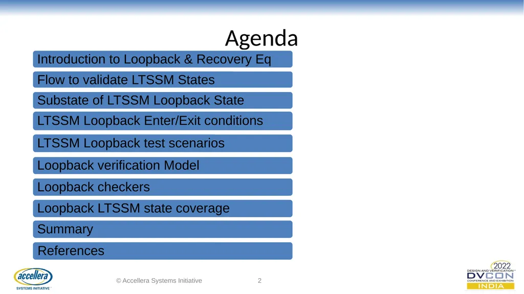
Agenda © Accellera Systems Initiative ‹#› Different conditio to Exit Loopback LTSSM state<br>
03
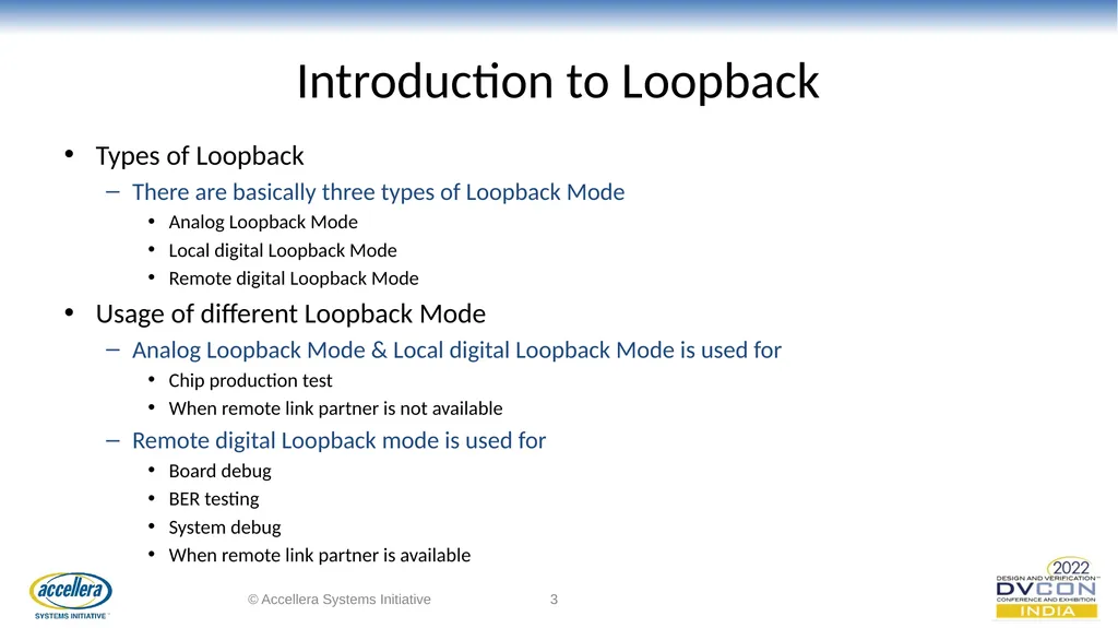
Introduction to Loopback Types of Loopback
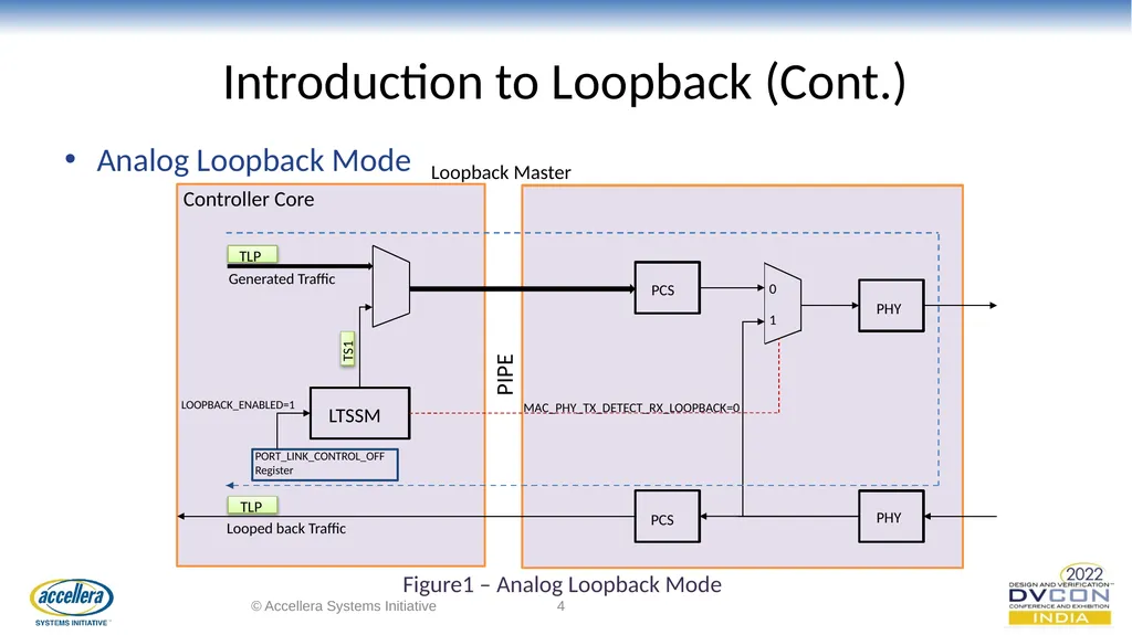
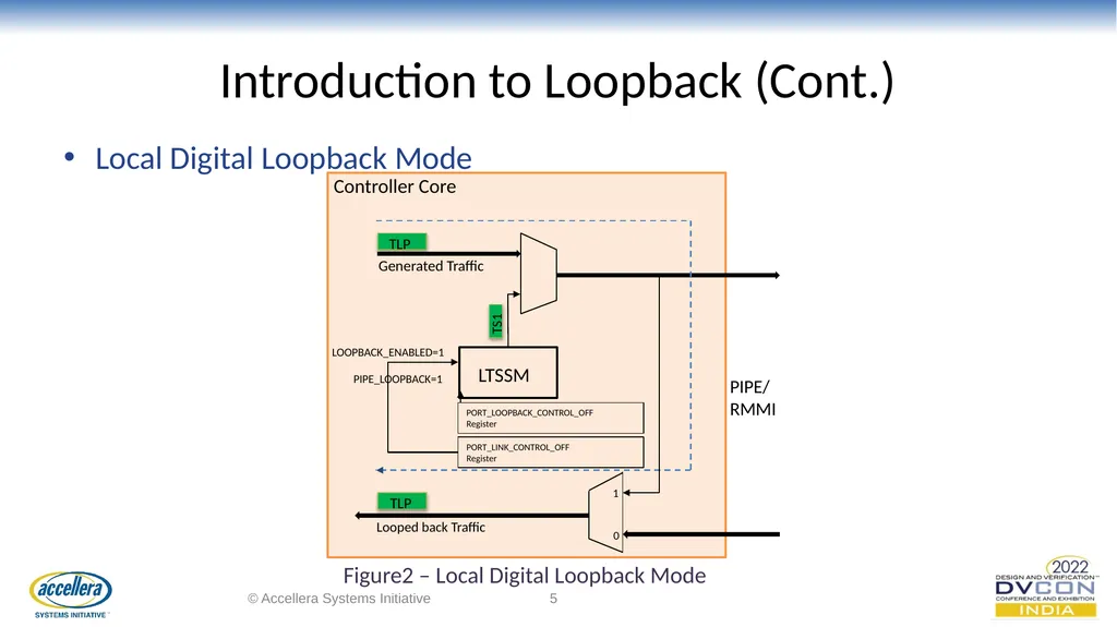
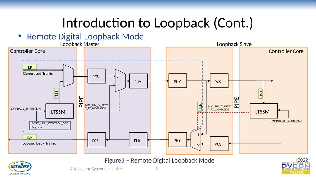
There are basically three types of Loopback Mode
Analog Loopback Mode
Local digital Loopback Mode
Remote digital Loopback Mode
Usage of different Loopback Mode
Analog Loopback Mode & Local digital Loopback Mode is used for
Chip production test
When remote link partner is not available
Remote digital Loopback mode is used for
Board debug
BER testing
System debug
When remote link partner is available © Accellera Systems Initiative ‹#›<br>
There are basically three types of Loopback Mode
Analog Loopback Mode
Local digital Loopback Mode
Remote digital Loopback Mode
Usage of different Loopback Mode
Analog Loopback Mode & Local digital Loopback Mode is used for
Chip production test
When remote link partner is not available
Remote digital Loopback mode is used for
Board debug
BER testing
System debug
When remote link partner is available © Accellera Systems Initiative ‹#›<br>
04
Introduction to Loopback (Cont.) Analog Loopback Mode © Accellera Systems Initiative ‹#› TLP TLP Controller Core Loopback Master Generated Traffic TS1 LTSSM Looped back Traffic LOOPBACK_ENABLED=1 PORT_LINK_CONTROL_OFF
Register PCS PCS PHY PHY 0 1 MAC_PHY_TX_DETECT_RX_LOOPBACK=0 PIPE Figure1 – Analog Loopback Mode<br>
Register PCS PCS PHY PHY 0 1 MAC_PHY_TX_DETECT_RX_LOOPBACK=0 PIPE Figure1 – Analog Loopback Mode<br>
05
Introduction to Loopback (Cont.) Local Digital Loopback Mode © Accellera Systems Initiative ‹#› TLP TLP Controller Core Generated Traffic TS1 LTSSM Looped back Traffic LOOPBACK_ENABLED=1 PORT_LOOPBACK_CONTROL_OFF
Register PORT_LINK_CONTROL_OFF
Register PIPE_LOOPBACK=1 1 0 PIPE/
RMMI Figure2 – Local Digital Loopback Mode<br>
Register PORT_LINK_CONTROL_OFF
Register PIPE_LOOPBACK=1 1 0 PIPE/
RMMI Figure2 – Local Digital Loopback Mode<br>
06
Introduction to Loopback (Cont.) Remote Digital Loopback Mode © Accellera Systems Initiative ‹#› TLP TLP Controller Core Loopback Master Generated Traffic TS1 LTSSM Looped back Traffic LOOPBACK_ENABLED=1 PORT_LINK_CONTROL_OFF
Register PCS PCS PHY PHY 0 1 MAC_PHY_TX_DETECT_RX_LOOPBACK=0 PIPE Loopback Slave PCS PCS PHY PHY LTSSM TLP TS1 1 0 PIPE MAC_PHY_TX_DETECT_RX_LOOPBACK=1 Controller Core LOOPBACK_ENABLED=0 Figure3 – Remote Digital Loopback Mode<br>
Register PCS PCS PHY PHY 0 1 MAC_PHY_TX_DETECT_RX_LOOPBACK=0 PIPE Loopback Slave PCS PCS PHY PHY LTSSM TLP TS1 1 0 PIPE MAC_PHY_TX_DETECT_RX_LOOPBACK=1 Controller Core LOOPBACK_ENABLED=0 Figure3 – Remote Digital Loopback Mode<br>
07
Introduction to Loopback (Cont.) Loopback is a powerful feature for the test and fault Isolation in the PCIe.
Loopback word stands that it is looping back the data, By using Loopback we can test interface independently from the other device.
In PCIe, Loopback can be used for per lane or configured link basis, and it can be used with all possible speed and encoding mechanisms like 8b/10b at GEN1 and GEN2, 128b/130b at GEN3,GEN4 and GEN5, and 1b/1b at GEN6.
In PCIe, Loopback connects the Tx to the Rx of a given set of PCIe lanes.
The PHY begins to Loopback data when the MAC assert TxDetextRx/Loopback.
In Loopback one device behave as a Loopback Master and other device behave as a Loopback slave,
Loopback Master:
A Loopback Master is the component requesting Loopback.
The entry mechanism for a Loopback Master is device specific.
The Loopback master can serve as the BIST (Built In Self Test) engine. © Accellera Systems Initiative ‹#›<br>
Loopback word stands that it is looping back the data, By using Loopback we can test interface independently from the other device.
In PCIe, Loopback can be used for per lane or configured link basis, and it can be used with all possible speed and encoding mechanisms like 8b/10b at GEN1 and GEN2, 128b/130b at GEN3,GEN4 and GEN5, and 1b/1b at GEN6.
In PCIe, Loopback connects the Tx to the Rx of a given set of PCIe lanes.
The PHY begins to Loopback data when the MAC assert TxDetextRx/Loopback.
In Loopback one device behave as a Loopback Master and other device behave as a Loopback slave,
Loopback Master:
A Loopback Master is the component requesting Loopback.
The entry mechanism for a Loopback Master is device specific.
The Loopback master can serve as the BIST (Built In Self Test) engine. © Accellera Systems Initiative ‹#›<br>
08
Introduction to Loopback (Cont.) Loopback Slave:
A Loopback Slave is the component looping back the data.
Loopback uses bit 2 (Loopback) in the Training Control field, which is sent within the TS1 and TS2 Ordered Sets.
The Loopback Slave device enters Loopback whenever two consecutive TS1 Ordered Sets are received with the Loopback bit set.
The Loopback slave continues to perform clock tolerance compensation by adding and deleting SKIP Symbols.
The Loopback state is exited when the Loopback master transmits the Electrical Idle Ordered-Set and the receiver detects that the Link has transitioned to the Electrical Idle state. © Accellera Systems Initiative ‹#›<br>
A Loopback Slave is the component looping back the data.
Loopback uses bit 2 (Loopback) in the Training Control field, which is sent within the TS1 and TS2 Ordered Sets.
The Loopback Slave device enters Loopback whenever two consecutive TS1 Ordered Sets are received with the Loopback bit set.
The Loopback slave continues to perform clock tolerance compensation by adding and deleting SKIP Symbols.
The Loopback state is exited when the Loopback master transmits the Electrical Idle Ordered-Set and the receiver detects that the Link has transitioned to the Electrical Idle state. © Accellera Systems Initiative ‹#›<br>
09
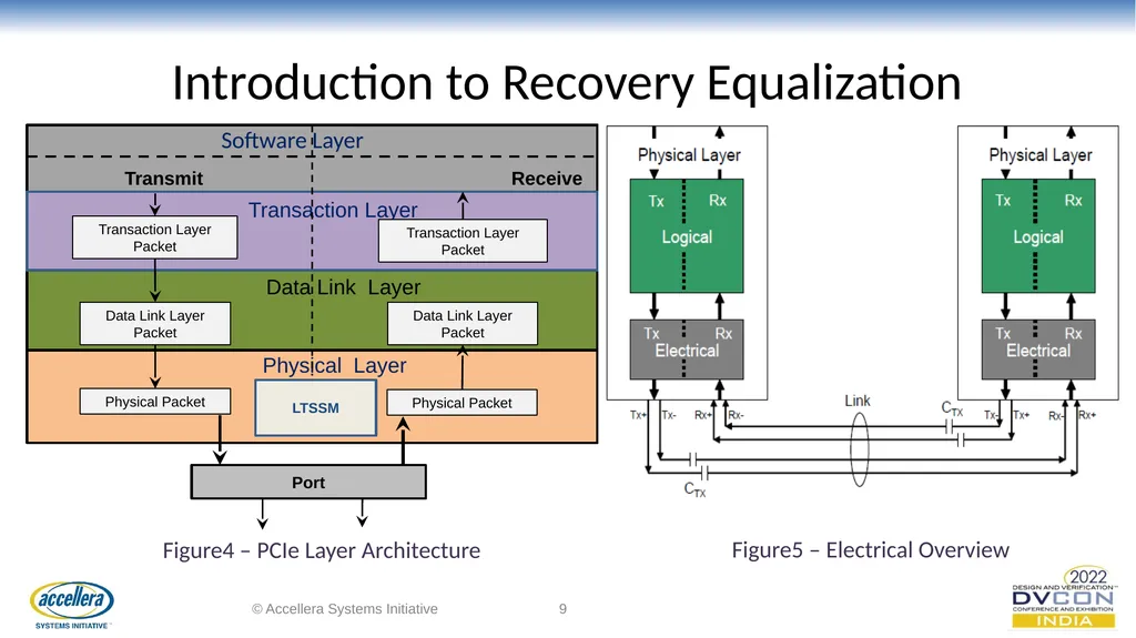
Introduction to Recovery Equalization © Accellera Systems Initiative ‹#› Physical Layer Transmit Receive Data Link Layer Transaction Layer Transaction Layer Packet Data Link Layer Packet Transaction Layer Packet Data Link Layer Packet Port Physical Packet Physical Packet LTSSM Software Layer Figure4 – PCIe Layer Architecture Figure5 – Electrical Overview<br>
10
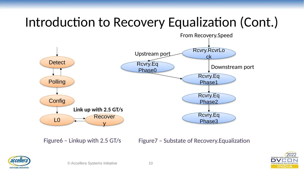
Introduction to Recovery Equalization (Cont.) © Accellera Systems Initiative ‹#› Detect Polling Recovery Config L0 Link up with 2.5 GT/s Rcvry.RcvrLock Rcvry.Eq Phase1 Rcvry.Eq Phase0 Rcvry.Eq Phase3 Rcvry.Eq Phase2 From Recovery.Speed Upstream port Downstream port Figure6 – Linkup with 2.5 GT/s Figure7 – Substate of Recovery.Equalization<br>
11
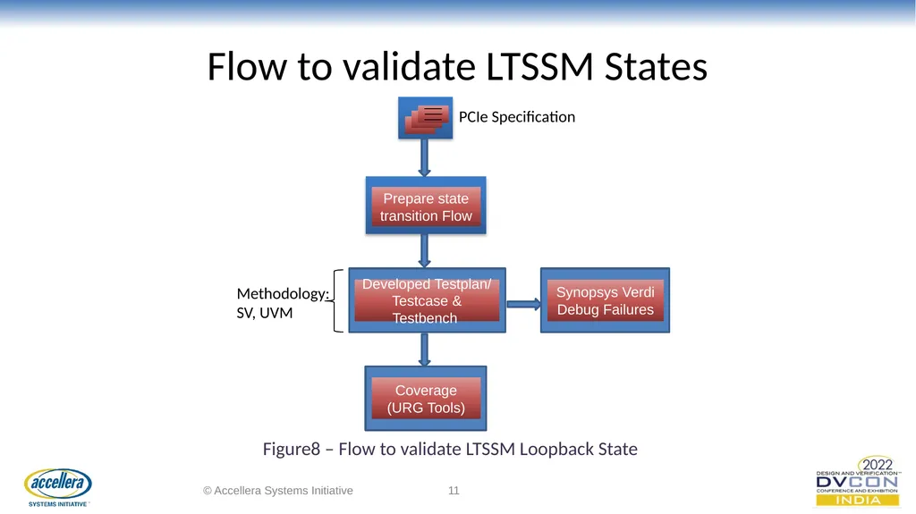
Flow to validate LTSSM States © Accellera Systems Initiative ‹#› PCIe Specification Prepare state transition Flow Developed Testplan/ Testcase & Testbench Coverage
(URG Tools) Synopsys Verdi
Debug Failures Methodology: SV, UVM Figure8 – Flow to validate LTSSM Loopback State<br>
(URG Tools) Synopsys Verdi
Debug Failures Methodology: SV, UVM Figure8 – Flow to validate LTSSM Loopback State<br>
12
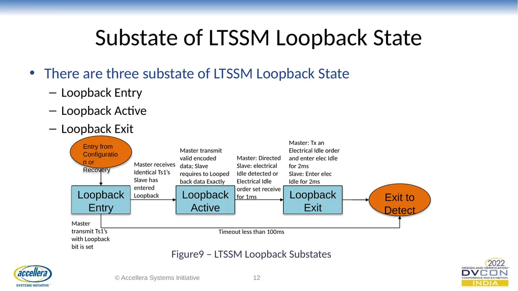
Substate of LTSSM Loopback State There are three substate of LTSSM Loopback State
Loopback Entry
Loopback Active
Loopback Exit © Accellera Systems Initiative ‹#› Entry from Configuration or Recovery Loopback Entry Loopback Active Loopback Exit Exit to Detect Master transmit Ts1’s with Loopback bit is set Timeout less than 100ms Master receives Identical Ts1’s Slave has entered Loopback Master transmit valid encoded data; Slave requires to Looped back data Exactly Master: Directed Slave: electrical Idle detected or Electrical Idle order set receive for 1ms Master: Tx an Electrical Idle order and enter elec Idle for 2ms
Slave: Enter elec Idle for 2ms Figure9 – LTSSM Loopback Substates<br>
Loopback Entry
Loopback Active
Loopback Exit © Accellera Systems Initiative ‹#› Entry from Configuration or Recovery Loopback Entry Loopback Active Loopback Exit Exit to Detect Master transmit Ts1’s with Loopback bit is set Timeout less than 100ms Master receives Identical Ts1’s Slave has entered Loopback Master transmit valid encoded data; Slave requires to Looped back data Exactly Master: Directed Slave: electrical Idle detected or Electrical Idle order set receive for 1ms Master: Tx an Electrical Idle order and enter elec Idle for 2ms
Slave: Enter elec Idle for 2ms Figure9 – LTSSM Loopback Substates<br>
13
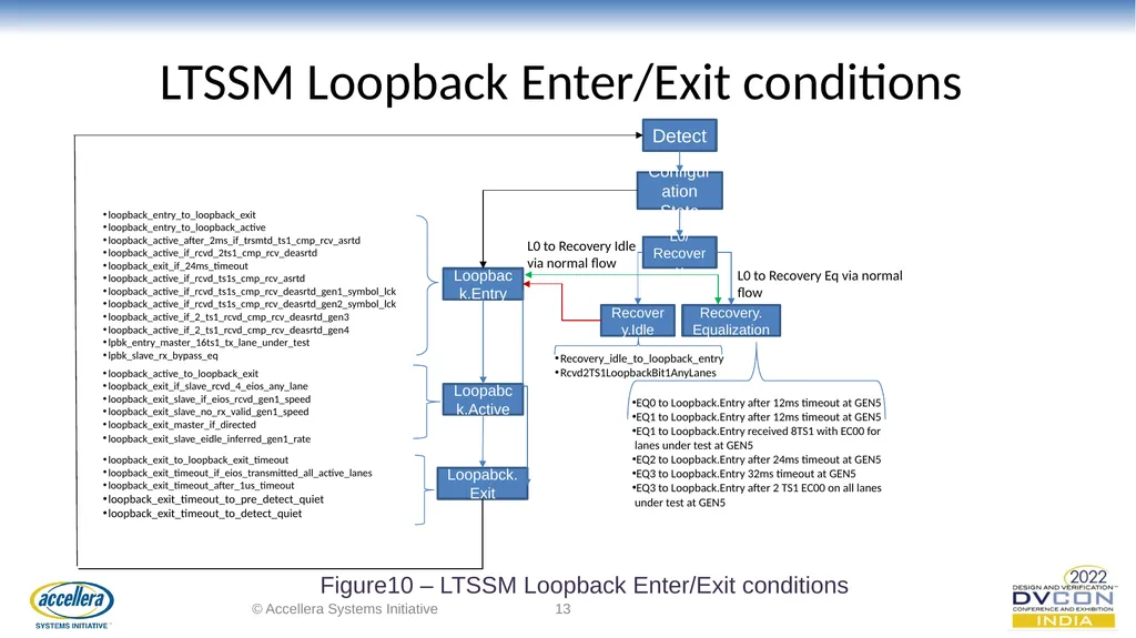
LTSSM Loopback Enter/Exit conditions © Accellera Systems Initiative ‹#› Detect Configuration State L0/ Recovery Recovery.Idle Loopback.Entry Loopabck.Active Loopabck. Exit Recovery_idle_to_loopback_entry
Rcvd2TS1LoopbackBit1AnyLanes loopback_entry_to_loopback_exit
loopback_entry_to_loopback_active
loopback_active_after_2ms_if_trsmtd_ts1_cmp_rcv_asrtd
loopback_active_if_rcvd_2ts1_cmp_rcv_deasrtd
loopback_exit_if_24ms_timeout
loopback_active_if_rcvd_ts1s_cmp_rcv_asrtd
loopback_active_if_rcvd_ts1s_cmp_rcv_deasrtd_gen1_symbol_lck
loopback_active_if_rcvd_ts1s_cmp_rcv_deasrtd_gen2_symbol_lck
loopback_active_if_2_ts1_rcvd_cmp_rcv_deasrtd_gen3
loopback_active_if_2_ts1_rcvd_cmp_rcv_deasrtd_gen4
lpbk_entry_master_16ts1_tx_lane_under_test
lpbk_slave_rx_bypass_eq loopback_active_to_loopback_exit
loopback_exit_if_slave_rcvd_4_eios_any_lane
loopback_exit_slave_if_eios_rcvd_gen1_speed
loopback_exit_slave_no_rx_valid_gen1_speed
loopback_exit_master_if_directed
loopback_exit_slave_eidle_inferred_gen1_rate loopback_exit_to_loopback_exit_timeout
loopback_exit_timeout_if_eios_transmitted_all_active_lanes
loopback_exit_timeout_after_1us_timeout
loopback_exit_timeout_to_pre_detect_quiet
loopback_exit_timeout_to_detect_quiet Recovery. Equalization L0 to Recovery Eq via normal flow L0 to Recovery Idle via normal flow EQ0 to Loopback.Entry after 12ms timeout at GEN5
EQ1 to Loopback.Entry after 12ms timeout at GEN5
EQ1 to Loopback.Entry received 8TS1 with EC00 for
lanes under test at GEN5
EQ2 to Loopback.Entry after 24ms timeout at GEN5
EQ3 to Loopback.Entry 32ms timeout at GEN5
EQ3 to Loopback.Entry after 2 TS1 EC00 on all lanes
under test at GEN5 Figure10 – LTSSM Loopback Enter/Exit conditions<br>
Rcvd2TS1LoopbackBit1AnyLanes loopback_entry_to_loopback_exit
loopback_entry_to_loopback_active
loopback_active_after_2ms_if_trsmtd_ts1_cmp_rcv_asrtd
loopback_active_if_rcvd_2ts1_cmp_rcv_deasrtd
loopback_exit_if_24ms_timeout
loopback_active_if_rcvd_ts1s_cmp_rcv_asrtd
loopback_active_if_rcvd_ts1s_cmp_rcv_deasrtd_gen1_symbol_lck
loopback_active_if_rcvd_ts1s_cmp_rcv_deasrtd_gen2_symbol_lck
loopback_active_if_2_ts1_rcvd_cmp_rcv_deasrtd_gen3
loopback_active_if_2_ts1_rcvd_cmp_rcv_deasrtd_gen4
lpbk_entry_master_16ts1_tx_lane_under_test
lpbk_slave_rx_bypass_eq loopback_active_to_loopback_exit
loopback_exit_if_slave_rcvd_4_eios_any_lane
loopback_exit_slave_if_eios_rcvd_gen1_speed
loopback_exit_slave_no_rx_valid_gen1_speed
loopback_exit_master_if_directed
loopback_exit_slave_eidle_inferred_gen1_rate loopback_exit_to_loopback_exit_timeout
loopback_exit_timeout_if_eios_transmitted_all_active_lanes
loopback_exit_timeout_after_1us_timeout
loopback_exit_timeout_to_pre_detect_quiet
loopback_exit_timeout_to_detect_quiet Recovery. Equalization L0 to Recovery Eq via normal flow L0 to Recovery Idle via normal flow EQ0 to Loopback.Entry after 12ms timeout at GEN5
EQ1 to Loopback.Entry after 12ms timeout at GEN5
EQ1 to Loopback.Entry received 8TS1 with EC00 for
lanes under test at GEN5
EQ2 to Loopback.Entry after 24ms timeout at GEN5
EQ3 to Loopback.Entry 32ms timeout at GEN5
EQ3 to Loopback.Entry after 2 TS1 EC00 on all lanes
under test at GEN5 Figure10 – LTSSM Loopback Enter/Exit conditions<br>
14
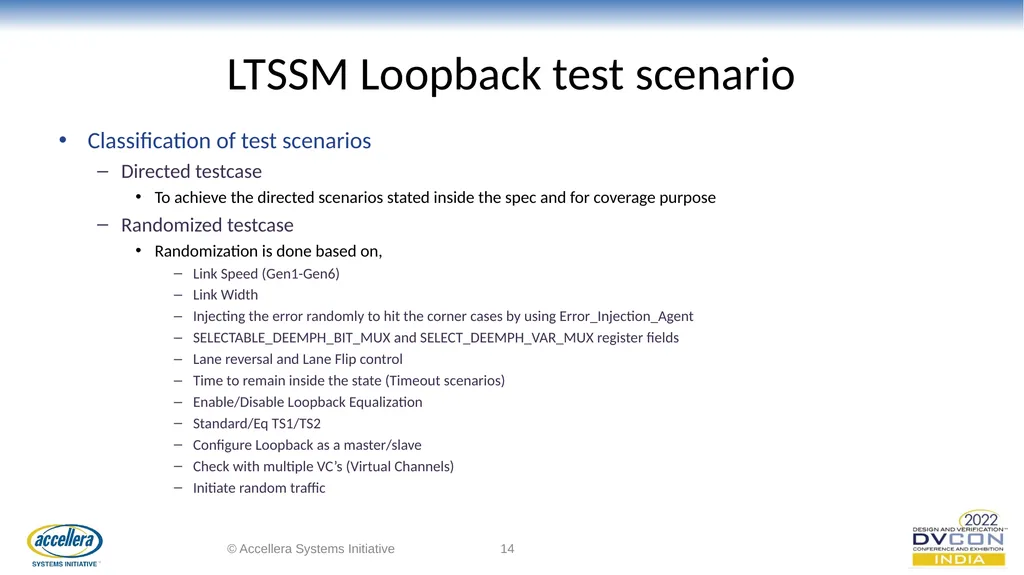
LTSSM Loopback test scenario Classification of test scenarios
Directed testcase
To achieve the directed scenarios stated inside the spec and for coverage purpose
Randomized testcase
Randomization is done based on,
Link Speed (Gen1-Gen6)
Link Width
Injecting the error randomly to hit the corner cases by using Error_Injection_Agent
SELECTABLE_DEEMPH_BIT_MUX and SELECT_DEEMPH_VAR_MUX register fields
Lane reversal and Lane Flip control
Time to remain inside the state (Timeout scenarios)
Enable/Disable Loopback Equalization
Standard/Eq TS1/TS2
Configure Loopback as a master/slave
Check with multiple VC’s (Virtual Channels)
Initiate random traffic © Accellera Systems Initiative ‹#›<br>
Directed testcase
To achieve the directed scenarios stated inside the spec and for coverage purpose
Randomized testcase
Randomization is done based on,
Link Speed (Gen1-Gen6)
Link Width
Injecting the error randomly to hit the corner cases by using Error_Injection_Agent
SELECTABLE_DEEMPH_BIT_MUX and SELECT_DEEMPH_VAR_MUX register fields
Lane reversal and Lane Flip control
Time to remain inside the state (Timeout scenarios)
Enable/Disable Loopback Equalization
Standard/Eq TS1/TS2
Configure Loopback as a master/slave
Check with multiple VC’s (Virtual Channels)
Initiate random traffic © Accellera Systems Initiative ‹#›<br>
15
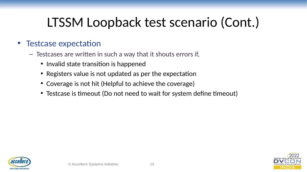
LTSSM Loopback test scenario (Cont.) Testcase expectation
Testcases are written in such a way that it shouts errors if,
Invalid state transition is happened
Registers value is not updated as per the expectation
Coverage is not hit (Helpful to achieve the coverage)
Testcase is timeout (Do not need to wait for system define timeout) © Accellera Systems Initiative ‹#›<br>
Testcases are written in such a way that it shouts errors if,
Invalid state transition is happened
Registers value is not updated as per the expectation
Coverage is not hit (Helpful to achieve the coverage)
Testcase is timeout (Do not need to wait for system define timeout) © Accellera Systems Initiative ‹#›<br>
16
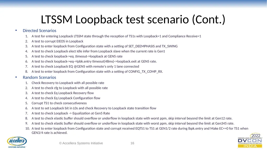
LTSSM Loopback test scenario (Cont.) Directed Scenarios
A test for entering Loopback LTSSM state through the reception of TS1s with Loopback=1 and Compliance Receive=1
A test to corrupt EIEOS in Loopback
A test to enter loopback from Configuration state with a setting of SET_DEEMPHASIS and TX_SWING
A test to check Loopback elect Idle infer from Loopback slave when the current rate is Gen1
A test to check loopback->eq .timeout->loopback at GEN5 rate
A test to check loopback->eq->lpbk.entry timeout(48ms)->loopback.exit at GEN5 rate.
A test to check Loopback EQ @GEN5 with remote's only 1 lane connected
A test to enter loopback from Configuration state with a setting of CONFIG_TX_COMP_RX.
Random Scenarios
Check Recovery to Loopback with all possible rate
A test to check cfg to Loopback with all possible rate
A test to check Eq Loopback Recovery flow
A test to check Eq Loopback Configuration flow
Corrupt TS1 to check consecutiveness
A test to set Loopback bit in L0s and check Recovery to Loopback state transition flow
A test to check Loopback -> Equalization at Gen5 Rate
A test to check elastic buffer should overflow or underflow in loopback state with worst ppm, skip interval beyond the limit at Gen12 rate.
A test to check elastic buffer should overflow or underflow in loopback state with worst ppm, skip interval beyond the limit at Gen345 rate.
A test to enter loopback from Configuration state and corrupt received EQTS1 to TS1 at GEN1/2 rate during lbpk.entry and Make EC==0 for TS1 when GEN3/4 rate is achieved. © Accellera Systems Initiative ‹#›<br>
A test for entering Loopback LTSSM state through the reception of TS1s with Loopback=1 and Compliance Receive=1
A test to corrupt EIEOS in Loopback
A test to enter loopback from Configuration state with a setting of SET_DEEMPHASIS and TX_SWING
A test to check Loopback elect Idle infer from Loopback slave when the current rate is Gen1
A test to check loopback->eq .timeout->loopback at GEN5 rate
A test to check loopback->eq->lpbk.entry timeout(48ms)->loopback.exit at GEN5 rate.
A test to check Loopback EQ @GEN5 with remote's only 1 lane connected
A test to enter loopback from Configuration state with a setting of CONFIG_TX_COMP_RX.
Random Scenarios
Check Recovery to Loopback with all possible rate
A test to check cfg to Loopback with all possible rate
A test to check Eq Loopback Recovery flow
A test to check Eq Loopback Configuration flow
Corrupt TS1 to check consecutiveness
A test to set Loopback bit in L0s and check Recovery to Loopback state transition flow
A test to check Loopback -> Equalization at Gen5 Rate
A test to check elastic buffer should overflow or underflow in loopback state with worst ppm, skip interval beyond the limit at Gen12 rate.
A test to check elastic buffer should overflow or underflow in loopback state with worst ppm, skip interval beyond the limit at Gen345 rate.
A test to enter loopback from Configuration state and corrupt received EQTS1 to TS1 at GEN1/2 rate during lbpk.entry and Make EC==0 for TS1 when GEN3/4 rate is achieved. © Accellera Systems Initiative ‹#›<br>
17
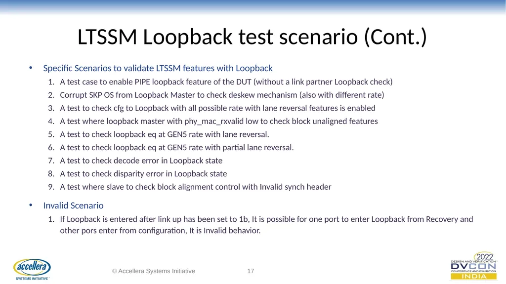
LTSSM Loopback test scenario (Cont.) Specific Scenarios to validate LTSSM features with Loopback
A test case to enable PIPE loopback feature of the DUT (without a link partner Loopback check)
Corrupt SKP OS from Loopback Master to check deskew mechanism (also with different rate)
A test to check cfg to Loopback with all possible rate with lane reversal features is enabled
A test where loopback master with phy_mac_rxvalid low to check block unaligned features
A test to check loopback eq at GEN5 rate with lane reversal.
A test to check loopback eq at GEN5 rate with partial lane reversal.
A test to check decode error in Loopback state
A test to check disparity error in Loopback state
A test where slave to check block alignment control with Invalid synch header
Invalid Scenario
If Loopback is entered after link up has been set to 1b, It is possible for one port to enter Loopback from Recovery and other pors enter from configuration, It is Invalid behavior. © Accellera Systems Initiative ‹#›<br>
A test case to enable PIPE loopback feature of the DUT (without a link partner Loopback check)
Corrupt SKP OS from Loopback Master to check deskew mechanism (also with different rate)
A test to check cfg to Loopback with all possible rate with lane reversal features is enabled
A test where loopback master with phy_mac_rxvalid low to check block unaligned features
A test to check loopback eq at GEN5 rate with lane reversal.
A test to check loopback eq at GEN5 rate with partial lane reversal.
A test to check decode error in Loopback state
A test to check disparity error in Loopback state
A test where slave to check block alignment control with Invalid synch header
Invalid Scenario
If Loopback is entered after link up has been set to 1b, It is possible for one port to enter Loopback from Recovery and other pors enter from configuration, It is Invalid behavior. © Accellera Systems Initiative ‹#›<br>
18
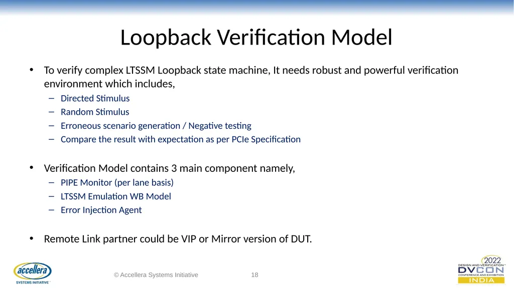
Loopback Verification Model To verify complex LTSSM Loopback state machine, It needs robust and powerful verification environment which includes,
Directed Stimulus
Random Stimulus
Erroneous scenario generation / Negative testing
Compare the result with expectation as per PCIe Specification
Verification Model contains 3 main component namely,
PIPE Monitor (per lane basis)
LTSSM Emulation WB Model
Error Injection Agent
Remote Link partner could be VIP or Mirror version of DUT. © Accellera Systems Initiative ‹#›<br>
Directed Stimulus
Random Stimulus
Erroneous scenario generation / Negative testing
Compare the result with expectation as per PCIe Specification
Verification Model contains 3 main component namely,
PIPE Monitor (per lane basis)
LTSSM Emulation WB Model
Error Injection Agent
Remote Link partner could be VIP or Mirror version of DUT. © Accellera Systems Initiative ‹#›<br>
19
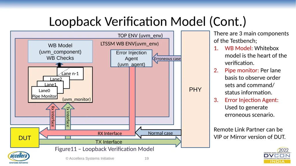
Loopback Verification Model (Cont.) © Accellera Systems Initiative ‹#› PHY WB Model (uvm_component)
WB Checks LTSSM WB ENV(uvm_env) TOP ENV (uvm_env) Error Injection Agent
(uvm_agent) DUT TX Interface Tx Interface Rx Interface RX Interface Lane0
Pipe Monitor Lane1 Lane2 Lane n-1 (uvm_monitor) Figure11 – Loopback Verification Model Normal case Erroneous case There are 3 main components of the Testbench;
WB Model: Whitebox model is the heart of the verification.
Pipe monitor: Per lane basis to observe order sets and command/ status information.
Error Injection Agent: Used to generate erroneous scenario.
Remote Link Partner can be VIP or Mirror version of DUT.<br>
WB Checks LTSSM WB ENV(uvm_env) TOP ENV (uvm_env) Error Injection Agent
(uvm_agent) DUT TX Interface Tx Interface Rx Interface RX Interface Lane0
Pipe Monitor Lane1 Lane2 Lane n-1 (uvm_monitor) Figure11 – Loopback Verification Model Normal case Erroneous case There are 3 main components of the Testbench;
WB Model: Whitebox model is the heart of the verification.
Pipe monitor: Per lane basis to observe order sets and command/ status information.
Error Injection Agent: Used to generate erroneous scenario.
Remote Link Partner can be VIP or Mirror version of DUT.<br>
20
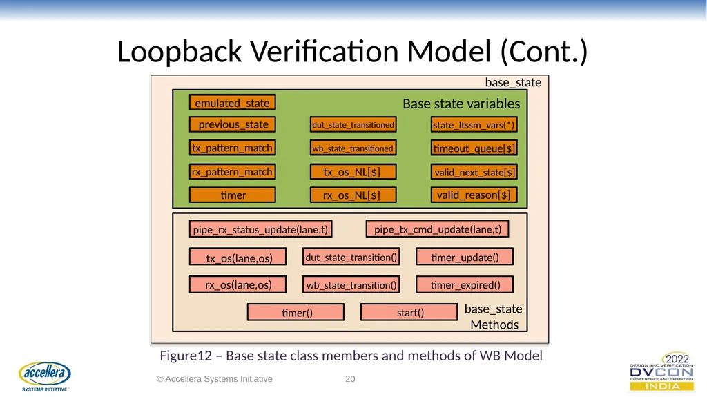
Loopback Verification Model (Cont.) © Accellera Systems Initiative ‹#› base_state base_state
Methods emulated_state previous_state tx_pattern_match rx_pattern_match timer dut_state_transitioned wb_state_transitioned state_ltssm_vars(*) tx_os_NL[$] rx_os_NL[$] timeout_queue[$] valid_next_state[$] valid_reason[$] pipe_rx_status_update(lane,t) pipe_tx_cmd_update(lane,t) tx_os(lane,os) rx_os(lane,os) dut_state_transition() wb_state_transition() timer() start() timer_update() timer_expired() Figure12 – Base state class members and methods of WB Model Base state variables<br>
Methods emulated_state previous_state tx_pattern_match rx_pattern_match timer dut_state_transitioned wb_state_transitioned state_ltssm_vars(*) tx_os_NL[$] rx_os_NL[$] timeout_queue[$] valid_next_state[$] valid_reason[$] pipe_rx_status_update(lane,t) pipe_tx_cmd_update(lane,t) tx_os(lane,os) rx_os(lane,os) dut_state_transition() wb_state_transition() timer() start() timer_update() timer_expired() Figure12 – Base state class members and methods of WB Model Base state variables<br>
21
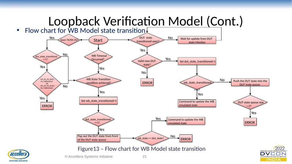
Loopback Verification Model (Cont.) Flow chart for WB Model state transition © Accellera Systems Initiative ‹#› Yes No Yes No Yes Yes Yes Yes Yes Yes Yes Yes Yes No No No Start Seen TX/RX OS? Dut_state_transitiond
==1? NO_OF_OS_SENT>
TX_THRESHOLD?
OR
NO_OF_OS_RCVD>
RX_THRESHOLD? ERROR ERROR ERROR ERROR WB Timeout
Occurred? WB State Transition condition achieved? Set wb_state_transitioned=1 dut_state_transitioned
==1? Pop out the DUT state from front of the DUT state queue wb_state == dut_state? No Command to update the WB emulated state Command to update the WB emulated state wb_state_transitioned
==1? DUT state transitioned seen? Valid new DUT
state? Wait for update from DUT
state Monitor Set dut_state_transitioned=1 Push the DUT state into the
DUT state queue DUT state queue size
> 2? Figure13 – Flow chart for WB Model state transition<br>
==1? NO_OF_OS_SENT>
TX_THRESHOLD?
OR
NO_OF_OS_RCVD>
RX_THRESHOLD? ERROR ERROR ERROR ERROR WB Timeout
Occurred? WB State Transition condition achieved? Set wb_state_transitioned=1 dut_state_transitioned
==1? Pop out the DUT state from front of the DUT state queue wb_state == dut_state? No Command to update the WB emulated state Command to update the WB emulated state wb_state_transitioned
==1? DUT state transitioned seen? Valid new DUT
state? Wait for update from DUT
state Monitor Set dut_state_transitioned=1 Push the DUT state into the
DUT state queue DUT state queue size
> 2? Figure13 – Flow chart for WB Model state transition<br>
22
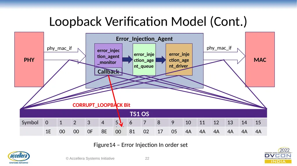
Loopback Verification Model (Cont.) © Accellera Systems Initiative ‹#› PHY MAC Error_Injection_Agent error_injection_agent_monitor error_injection_agent_driver error_injection_agent_queue phy_mac_if phy_mac_if Callback TS1 OS CORRUPT_LOOPBACK Bit 00 Figure14 – Error Injection In order set<br>
23
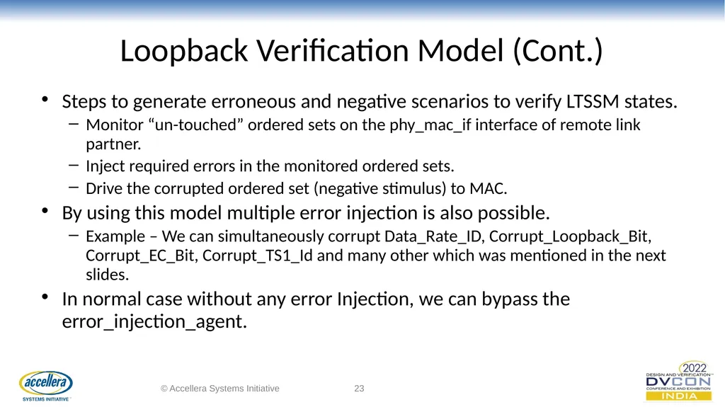
Loopback Verification Model (Cont.) Steps to generate erroneous and negative scenarios to verify LTSSM states.
Monitor “un-touched” ordered sets on the phy_mac_if interface of remote link partner.
Inject required errors in the monitored ordered sets.
Drive the corrupted ordered set (negative stimulus) to MAC.
By using this model multiple error injection is also possible.
Example – We can simultaneously corrupt Data_Rate_ID, Corrupt_Loopback_Bit, Corrupt_EC_Bit, Corrupt_TS1_Id and many other which was mentioned in the next slides.
In normal case without any error Injection, we can bypass the error_injection_agent. © Accellera Systems Initiative ‹#›<br>
Monitor “un-touched” ordered sets on the phy_mac_if interface of remote link partner.
Inject required errors in the monitored ordered sets.
Drive the corrupted ordered set (negative stimulus) to MAC.
By using this model multiple error injection is also possible.
Example – We can simultaneously corrupt Data_Rate_ID, Corrupt_Loopback_Bit, Corrupt_EC_Bit, Corrupt_TS1_Id and many other which was mentioned in the next slides.
In normal case without any error Injection, we can bypass the error_injection_agent. © Accellera Systems Initiative ‹#›<br>
24
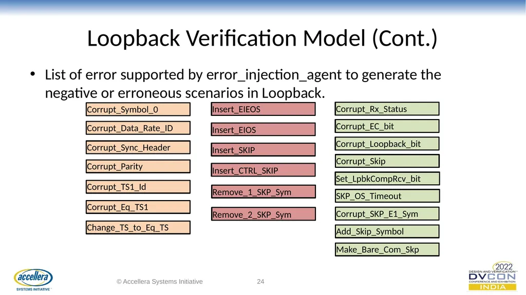
Loopback Verification Model (Cont.) List of error supported by error_injection_agent to generate the negative or erroneous scenarios in Loopback. © Accellera Systems Initiative ‹#› Corrupt_Symbol_0 Corrupt_Data_Rate_ID Corrupt_Sync_Header Corrupt_Parity Corrupt_TS1_Id Corrupt_Eq_TS1 Insert_EIEOS Insert_EIOS Insert_SKIP Insert_CTRL_SKIP Corrupt_Rx_Status Corrupt_EC_bit Corrupt_Loopback_bit Corrupt_Skip Change_TS_to_Eq_TS Set_LpbkCompRcv_bit SKP_OS_Timeout Corrupt_SKP_E1_Sym Add_Skip_Symbol Make_Bare_Com_Skp Remove_1_SKP_Sym Remove_2_SKP_Sym<br>
25
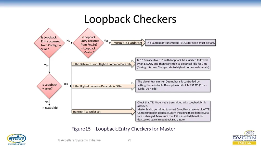
Loopback Checkers © Accellera Systems Initiative ‹#› Is Loopback. Entry occurred from Config.Lw. Start? No Yes Is Loopback
Master? No In next slide Yes If the Data rate is not Highest common Data rate Tx 16 Consecutive TS1 with loopback bit asserted followed by an EIEOSQ and then transition to electrical Idle for 1ms (During this time Change rate to highest common data rate) If the Highest common Data rate is 5Gt/s The slave’s transmitter Deemphasis is controlled by setting the selectable Deemphasis bit of Tx TS1 OS (1b = -3.5dB, 0b = 6dB). Transmit TS1 Order set Check that TS1 Order set is transmitted with Loopback bit is asserted.
Master is also permitted to assert Compliance receive bit of TS1 OS transmitted in Loopback.Entry, Including those before Data rate is changed, Make sure that If it is asserted then it not deasserted again in Loopback.Entry State. Is Loopback. Entry occurred from Rec.Eq?
Is Loopback
Master? Yes Transmit TS1 Order set The EC field of transmitted TS1 Order set is must be 00b. Figure15 – Loopback.Entry Checkers for Master<br>
Master? No In next slide Yes If the Data rate is not Highest common Data rate Tx 16 Consecutive TS1 with loopback bit asserted followed by an EIEOSQ and then transition to electrical Idle for 1ms (During this time Change rate to highest common data rate) If the Highest common Data rate is 5Gt/s The slave’s transmitter Deemphasis is controlled by setting the selectable Deemphasis bit of Tx TS1 OS (1b = -3.5dB, 0b = 6dB). Transmit TS1 Order set Check that TS1 Order set is transmitted with Loopback bit is asserted.
Master is also permitted to assert Compliance receive bit of TS1 OS transmitted in Loopback.Entry, Including those before Data rate is changed, Make sure that If it is asserted then it not deasserted again in Loopback.Entry State. Is Loopback. Entry occurred from Rec.Eq?
Is Loopback
Master? Yes Transmit TS1 Order set The EC field of transmitted TS1 Order set is must be 00b. Figure15 – Loopback.Entry Checkers for Master<br>
26
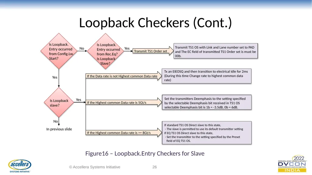
Loopback Checkers (Cont.) © Accellera Systems Initiative ‹#› Is Loopback. Entry occurred from Config.Lw. Start? No Yes Is Loopback slave? No In previous slide Yes If the Data rate is not Highest common Data rate Tx an EIEOSQ and then transition to electrical Idle for 2ms (During this time Change rate to highest common data rate) If the Highest common Data rate is 5Gt/s Set the transmitters Deemphasis to the setting specified by the selectable Deemphasis bit received in TS1 OS selectable Deemphasis bit is 1b = -3.5dB, 0b = 6dB. If the Highest common Data rate is >= 8Gt/s If standard TS1 OS Direct slave to this state,
- The slave is permitted to use its default transmitter setting
If EQ TS1 OS Direct slave to this state,
- Set the transmitter to the setting specified by the Preset
field of EQ TS1 OS. Figure16 – Loopback.Entry Checkers for Slave Is Loopback. Entry occurred from Rec.Eq?
Is Loopback
Slave? Yes Transmit TS1 Order set Transmit TS1 OS with Link and Lane number set to PAD and The EC field of transmitted TS1 Order set is must be 00b.<br>
- The slave is permitted to use its default transmitter setting
If EQ TS1 OS Direct slave to this state,
- Set the transmitter to the setting specified by the Preset
field of EQ TS1 OS. Figure16 – Loopback.Entry Checkers for Slave Is Loopback. Entry occurred from Rec.Eq?
Is Loopback
Slave? Yes Transmit TS1 Order set Transmit TS1 OS with Link and Lane number set to PAD and The EC field of transmitted TS1 Order set is must be 00b.<br>
27
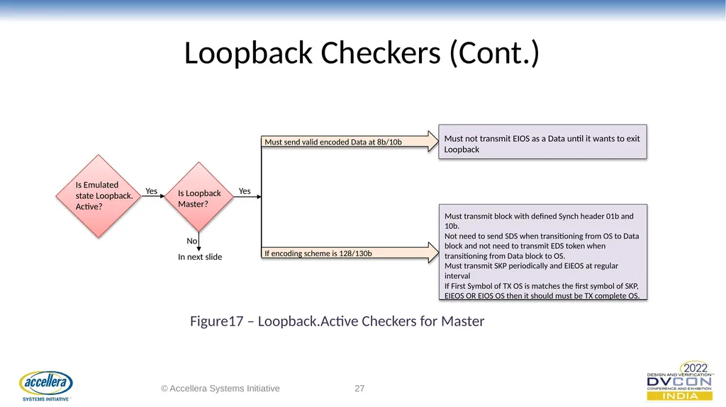
Loopback Checkers (Cont.) © Accellera Systems Initiative ‹#› Is Loopback
Master? No In next slide Yes Must send valid encoded Data at 8b/10b Must not transmit EIOS as a Data until it wants to exit Loopback If encoding scheme is 128/130b Must transmit block with defined Synch header 01b and 10b. Not need to send SDS when transitioning from OS to Data block and not need to transmit EDS token when transitioning from Data block to OS.
Must transmit SKP periodically and EIEOS at regular interval
If First Symbol of TX OS is matches the first symbol of SKP, EIEOS OR EIOS OS then it should must be TX complete OS. Is Emulated state Loopback. Active? Yes Figure17 – Loopback.Active Checkers for Master<br>
Master? No In next slide Yes Must send valid encoded Data at 8b/10b Must not transmit EIOS as a Data until it wants to exit Loopback If encoding scheme is 128/130b Must transmit block with defined Synch header 01b and 10b. Not need to send SDS when transitioning from OS to Data block and not need to transmit EDS token when transitioning from Data block to OS.
Must transmit SKP periodically and EIEOS at regular interval
If First Symbol of TX OS is matches the first symbol of SKP, EIEOS OR EIOS OS then it should must be TX complete OS. Is Emulated state Loopback. Active? Yes Figure17 – Loopback.Active Checkers for Master<br>
28
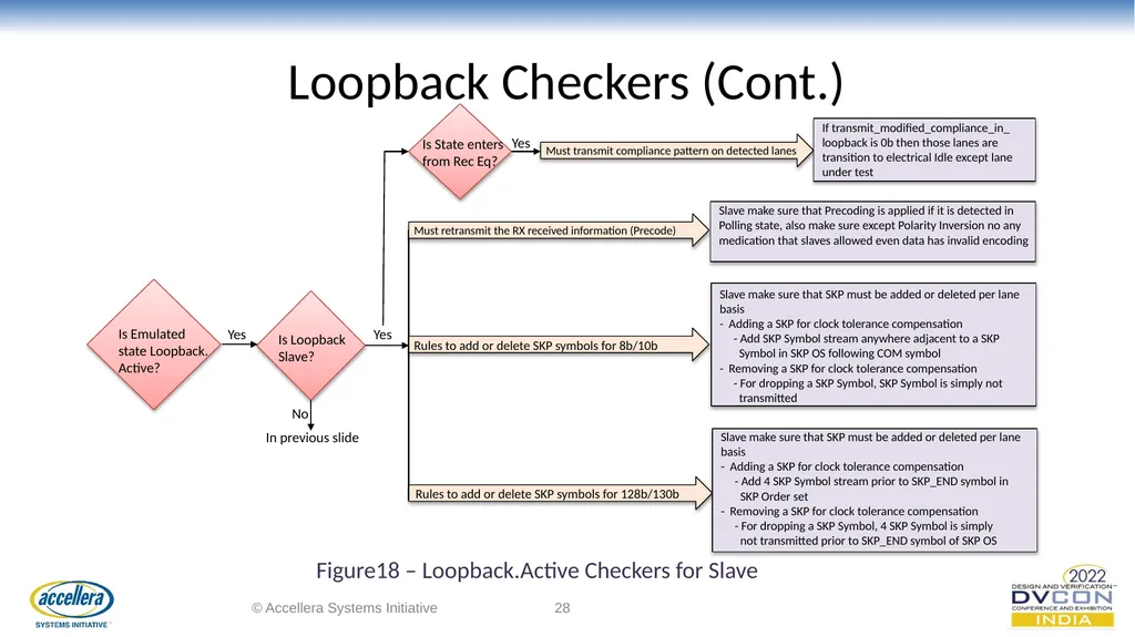
Loopback Checkers (Cont.) © Accellera Systems Initiative ‹#› Is Loopback
Slave? In previous slide Yes Must retransmit the RX received information (Precode) Slave make sure that Precoding is applied if it is detected in Polling state, also make sure except Polarity Inversion no any medication that slaves allowed even data has invalid encoding Rules to add or delete SKP symbols for 8b/10b Slave make sure that SKP must be added or deleted per lane basis
- Adding a SKP for clock tolerance compensation
- Add SKP Symbol stream anywhere adjacent to a SKP
Symbol in SKP OS following COM symbol
- Removing a SKP for clock tolerance compensation
- For dropping a SKP Symbol, SKP Symbol is simply not
transmitted Figure18 – Loopback.Active Checkers for Slave Is Emulated state Loopback. Active? Yes Rules to add or delete SKP symbols for 128b/130b Slave make sure that SKP must be added or deleted per lane basis
- Adding a SKP for clock tolerance compensation
- Add 4 SKP Symbol stream prior to SKP_END symbol in
SKP Order set
- Removing a SKP for clock tolerance compensation
- For dropping a SKP Symbol, 4 SKP Symbol is simply
not transmitted prior to SKP_END symbol of SKP OS Is State enters from Rec Eq? Yes Must transmit compliance pattern on detected lanes If transmit_modified_compliance_in_ loopback is 0b then those lanes are transition to electrical Idle except lane under test No<br>
Slave? In previous slide Yes Must retransmit the RX received information (Precode) Slave make sure that Precoding is applied if it is detected in Polling state, also make sure except Polarity Inversion no any medication that slaves allowed even data has invalid encoding Rules to add or delete SKP symbols for 8b/10b Slave make sure that SKP must be added or deleted per lane basis
- Adding a SKP for clock tolerance compensation
- Add SKP Symbol stream anywhere adjacent to a SKP
Symbol in SKP OS following COM symbol
- Removing a SKP for clock tolerance compensation
- For dropping a SKP Symbol, SKP Symbol is simply not
transmitted Figure18 – Loopback.Active Checkers for Slave Is Emulated state Loopback. Active? Yes Rules to add or delete SKP symbols for 128b/130b Slave make sure that SKP must be added or deleted per lane basis
- Adding a SKP for clock tolerance compensation
- Add 4 SKP Symbol stream prior to SKP_END symbol in
SKP Order set
- Removing a SKP for clock tolerance compensation
- For dropping a SKP Symbol, 4 SKP Symbol is simply
not transmitted prior to SKP_END symbol of SKP OS Is State enters from Rec Eq? Yes Must transmit compliance pattern on detected lanes If transmit_modified_compliance_in_ loopback is 0b then those lanes are transition to electrical Idle except lane under test No<br>
29
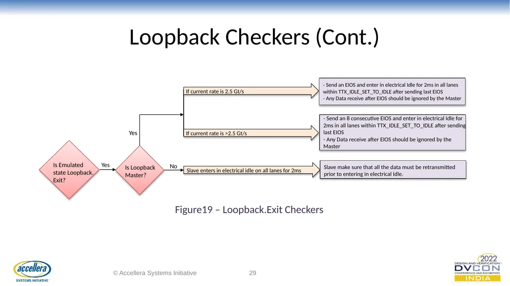
Loopback Checkers (Cont.) © Accellera Systems Initiative ‹#› Is Loopback
Master? No If current rate is 2.5 Gt/s - Send an EIOS and enter in electrical Idle for 2ms in all lanes within TTX_IDLE_SET_TO_IDLE after sending last EIOS
- Any Data receive after EIOS should be ignored by the Master If current rate is >2.5 Gt/s - Send an 8 consecutive EIOS and enter in electrical Idle for 2ms in all lanes within TTX_IDLE_SET_TO_IDLE after sending last EIOS
- Any Data receive after EIOS should be ignored by the Master Is Emulated state Loopback. Exit? Yes Slave enters in electrical idle on all lanes for 2ms Slave make sure that all the data must be retransmitted prior to entering in electrical Idle. Yes Figure19 – Loopback.Exit Checkers<br>
Master? No If current rate is 2.5 Gt/s - Send an EIOS and enter in electrical Idle for 2ms in all lanes within TTX_IDLE_SET_TO_IDLE after sending last EIOS
- Any Data receive after EIOS should be ignored by the Master If current rate is >2.5 Gt/s - Send an 8 consecutive EIOS and enter in electrical Idle for 2ms in all lanes within TTX_IDLE_SET_TO_IDLE after sending last EIOS
- Any Data receive after EIOS should be ignored by the Master Is Emulated state Loopback. Exit? Yes Slave enters in electrical idle on all lanes for 2ms Slave make sure that all the data must be retransmitted prior to entering in electrical Idle. Yes Figure19 – Loopback.Exit Checkers<br>
30
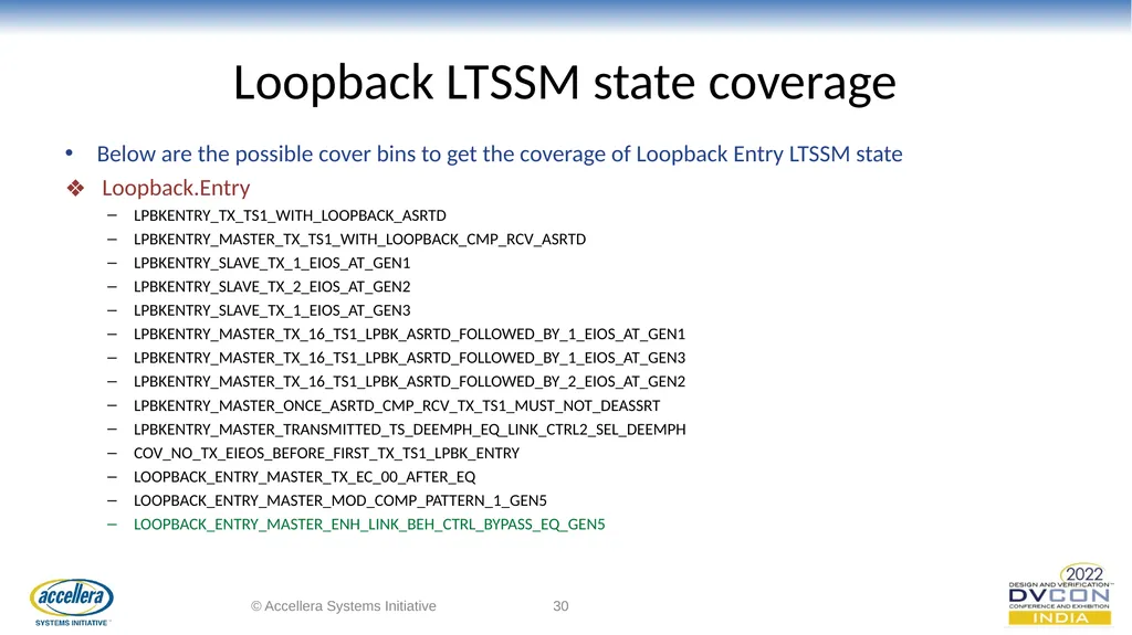
Loopback LTSSM state coverage Below are the possible cover bins to get the coverage of Loopback Entry LTSSM state
Loopback.Entry
LPBKENTRY_TX_TS1_WITH_LOOPBACK_ASRTD
LPBKENTRY_MASTER_TX_TS1_WITH_LOOPBACK_CMP_RCV_ASRTD
LPBKENTRY_SLAVE_TX_1_EIOS_AT_GEN1
LPBKENTRY_SLAVE_TX_2_EIOS_AT_GEN2
LPBKENTRY_SLAVE_TX_1_EIOS_AT_GEN3
LPBKENTRY_MASTER_TX_16_TS1_LPBK_ASRTD_FOLLOWED_BY_1_EIOS_AT_GEN1
LPBKENTRY_MASTER_TX_16_TS1_LPBK_ASRTD_FOLLOWED_BY_1_EIOS_AT_GEN3
LPBKENTRY_MASTER_TX_16_TS1_LPBK_ASRTD_FOLLOWED_BY_2_EIOS_AT_GEN2
LPBKENTRY_MASTER_ONCE_ASRTD_CMP_RCV_TX_TS1_MUST_NOT_DEASSRT
LPBKENTRY_MASTER_TRANSMITTED_TS_DEEMPH_EQ_LINK_CTRL2_SEL_DEEMPH
COV_NO_TX_EIEOS_BEFORE_FIRST_TX_TS1_LPBK_ENTRY
LOOPBACK_ENTRY_MASTER_TX_EC_00_AFTER_EQ
LOOPBACK_ENTRY_MASTER_MOD_COMP_PATTERN_1_GEN5
LOOPBACK_ENTRY_MASTER_ENH_LINK_BEH_CTRL_BYPASS_EQ_GEN5 © Accellera Systems Initiative ‹#›<br>
Loopback.Entry
LPBKENTRY_TX_TS1_WITH_LOOPBACK_ASRTD
LPBKENTRY_MASTER_TX_TS1_WITH_LOOPBACK_CMP_RCV_ASRTD
LPBKENTRY_SLAVE_TX_1_EIOS_AT_GEN1
LPBKENTRY_SLAVE_TX_2_EIOS_AT_GEN2
LPBKENTRY_SLAVE_TX_1_EIOS_AT_GEN3
LPBKENTRY_MASTER_TX_16_TS1_LPBK_ASRTD_FOLLOWED_BY_1_EIOS_AT_GEN1
LPBKENTRY_MASTER_TX_16_TS1_LPBK_ASRTD_FOLLOWED_BY_1_EIOS_AT_GEN3
LPBKENTRY_MASTER_TX_16_TS1_LPBK_ASRTD_FOLLOWED_BY_2_EIOS_AT_GEN2
LPBKENTRY_MASTER_ONCE_ASRTD_CMP_RCV_TX_TS1_MUST_NOT_DEASSRT
LPBKENTRY_MASTER_TRANSMITTED_TS_DEEMPH_EQ_LINK_CTRL2_SEL_DEEMPH
COV_NO_TX_EIEOS_BEFORE_FIRST_TX_TS1_LPBK_ENTRY
LOOPBACK_ENTRY_MASTER_TX_EC_00_AFTER_EQ
LOOPBACK_ENTRY_MASTER_MOD_COMP_PATTERN_1_GEN5
LOOPBACK_ENTRY_MASTER_ENH_LINK_BEH_CTRL_BYPASS_EQ_GEN5 © Accellera Systems Initiative ‹#›<br>
31
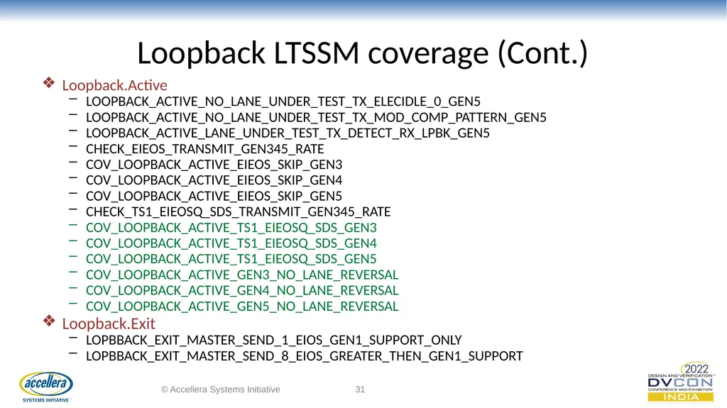
Loopback LTSSM coverage (Cont.) Loopback.Active
LOOPBACK_ACTIVE_NO_LANE_UNDER_TEST_TX_ELECIDLE_0_GEN5
LOOPBACK_ACTIVE_NO_LANE_UNDER_TEST_TX_MOD_COMP_PATTERN_GEN5
LOOPBACK_ACTIVE_LANE_UNDER_TEST_TX_DETECT_RX_LPBK_GEN5
CHECK_EIEOS_TRANSMIT_GEN345_RATE
COV_LOOPBACK_ACTIVE_EIEOS_SKIP_GEN3
COV_LOOPBACK_ACTIVE_EIEOS_SKIP_GEN4
COV_LOOPBACK_ACTIVE_EIEOS_SKIP_GEN5
CHECK_TS1_EIEOSQ_SDS_TRANSMIT_GEN345_RATE
COV_LOOPBACK_ACTIVE_TS1_EIEOSQ_SDS_GEN3
COV_LOOPBACK_ACTIVE_TS1_EIEOSQ_SDS_GEN4
COV_LOOPBACK_ACTIVE_TS1_EIEOSQ_SDS_GEN5
COV_LOOPBACK_ACTIVE_GEN3_NO_LANE_REVERSAL
COV_LOOPBACK_ACTIVE_GEN4_NO_LANE_REVERSAL
COV_LOOPBACK_ACTIVE_GEN5_NO_LANE_REVERSAL
Loopback.Exit
LOPBBACK_EXIT_MASTER_SEND_1_EIOS_GEN1_SUPPORT_ONLY
LOPBBACK_EXIT_MASTER_SEND_8_EIOS_GREATER_THEN_GEN1_SUPPORT © Accellera Systems Initiative ‹#›<br>
LOOPBACK_ACTIVE_NO_LANE_UNDER_TEST_TX_ELECIDLE_0_GEN5
LOOPBACK_ACTIVE_NO_LANE_UNDER_TEST_TX_MOD_COMP_PATTERN_GEN5
LOOPBACK_ACTIVE_LANE_UNDER_TEST_TX_DETECT_RX_LPBK_GEN5
CHECK_EIEOS_TRANSMIT_GEN345_RATE
COV_LOOPBACK_ACTIVE_EIEOS_SKIP_GEN3
COV_LOOPBACK_ACTIVE_EIEOS_SKIP_GEN4
COV_LOOPBACK_ACTIVE_EIEOS_SKIP_GEN5
CHECK_TS1_EIEOSQ_SDS_TRANSMIT_GEN345_RATE
COV_LOOPBACK_ACTIVE_TS1_EIEOSQ_SDS_GEN3
COV_LOOPBACK_ACTIVE_TS1_EIEOSQ_SDS_GEN4
COV_LOOPBACK_ACTIVE_TS1_EIEOSQ_SDS_GEN5
COV_LOOPBACK_ACTIVE_GEN3_NO_LANE_REVERSAL
COV_LOOPBACK_ACTIVE_GEN4_NO_LANE_REVERSAL
COV_LOOPBACK_ACTIVE_GEN5_NO_LANE_REVERSAL
Loopback.Exit
LOPBBACK_EXIT_MASTER_SEND_1_EIOS_GEN1_SUPPORT_ONLY
LOPBBACK_EXIT_MASTER_SEND_8_EIOS_GREATER_THEN_GEN1_SUPPORT © Accellera Systems Initiative ‹#›<br>
32
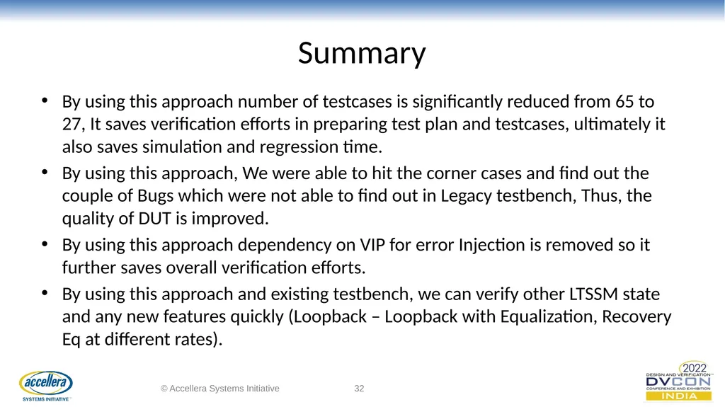
Summary By using this approach number of testcases is significantly reduced from 65 to 27, It saves verification efforts in preparing test plan and testcases, ultimately it also saves simulation and regression time.
By using this approach, We were able to hit the corner cases and find out the couple of Bugs which were not able to find out in Legacy testbench, Thus, the quality of DUT is improved.
By using this approach dependency on VIP for error Injection is removed so it further saves overall verification efforts.
By using this approach and existing testbench, we can verify other LTSSM state and any new features quickly (Loopback – Loopback with Equalization, Recovery Eq at different rates). © Accellera Systems Initiative ‹#›<br>
By using this approach, We were able to hit the corner cases and find out the couple of Bugs which were not able to find out in Legacy testbench, Thus, the quality of DUT is improved.
By using this approach dependency on VIP for error Injection is removed so it further saves overall verification efforts.
By using this approach and existing testbench, we can verify other LTSSM state and any new features quickly (Loopback – Loopback with Equalization, Recovery Eq at different rates). © Accellera Systems Initiative ‹#›<br>
33
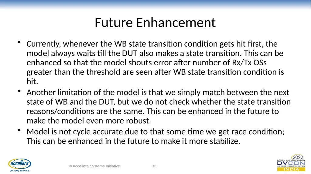
Future Enhancement Currently, whenever the WB state transition condition gets hit first, the model always waits till the DUT also makes a state transition. This can be enhanced so that the model shouts error after number of Rx/Tx OSs greater than the threshold are seen after WB state transition condition is hit.
Another limitation of the model is that we simply match between the next state of WB and the DUT, but we do not check whether the state transition reasons/conditions are the same. This can be enhanced in the future to make the model even more robust.
Model is not cycle accurate due to that some time we get race condition; This can be enhanced in the future to make it more stabilize. © Accellera Systems Initiative ‹#›<br>
Another limitation of the model is that we simply match between the next state of WB and the DUT, but we do not check whether the state transition reasons/conditions are the same. This can be enhanced in the future to make the model even more robust.
Model is not cycle accurate due to that some time we get race condition; This can be enhanced in the future to make it more stabilize. © Accellera Systems Initiative ‹#›<br>
34
Reference PCIe Base Specification
PIPE Base Specification
PCIe VIP Development project © Accellera Systems Initiative ‹#›<br>
PIPE Base Specification
PCIe VIP Development project © Accellera Systems Initiative ‹#›<br>
35
Acknowledgment © Accellera Systems Initiative ‹#› Author: Jaydeep Suvariya
Jaydeep.suvariya@einfochips.com https://www.linkedin.com/in/jaydeep-suvariya-838b80102/ Co-Author: Pinal Patel
pinal.patel@einfochips.com
https://www.linkedin.com/in/pinal-patel-b206a818/ Pranav Joshi
pranav.joshi@einfochips.com https://www.linkedin.com/in/pranav-joshi-455965/<br>
Jaydeep.suvariya@einfochips.com https://www.linkedin.com/in/jaydeep-suvariya-838b80102/ Co-Author: Pinal Patel
pinal.patel@einfochips.com
https://www.linkedin.com/in/pinal-patel-b206a818/ Pranav Joshi
pranav.joshi@einfochips.com https://www.linkedin.com/in/pranav-joshi-455965/<br>
36
© Accellera Systems Initiative ‹#› Thank you
Any Questions?<br>
Any Questions?<br>