
Electrical Resistivity Method Senior Chief
Description: Electrical Resistivity Method Senior Chief Geologists Dr. Firas AL-Menshed Head of Geophysics Division Lecture 1 Resistivity Equation Ministry of water resources General commission for groundwater Geophysics division The DC resistivity
Related Topics
Download Presentation
"Electrical Resistivity Method Senior Chief" is the property of its rightful owner. Permission is granted to download and print the materials on this website for personal, non-commercial use only, and to display it on your personal computer provided you do not modify the materials and that you retain all copyright notices contained in the materials. By downloading content from our website, you accept the terms of this agreement.
Presentation Transcript
slide1. Electrical Resistivity Method Senior Chief Geologists
Dr. Firas AL-Menshed
Head of Geophysics Division
Lecture 1
Resistivity Equation Ministry of water resources
General commission for groundwater
Geophysics division<br>
slide2. The DC resistivity method is one of the simplest geophysical techniques used to measure earth resistivity, but it is still employed extensively because of its easy using and relatively easy interpretation. The most common application is groundwater exploration, but it is also used in geothermal, environmental, and engineering studies. The measurement of the earth’s resistivity is very similar in concept to the laboratory resistivity measurement of rock samples. A DC electric current is passed through the ground via a pair of current electrodes and a resulting potential difference is measured between a second pair of potential electrodes. Introduction<br>
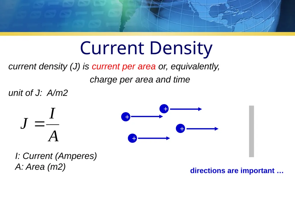
slide3. current density (J) is current per area or, equivalently,
charge per area and time
unit of J: A/m2 directions are important … I: Current (Amperes)
A: Area (m2) Current Density<br>
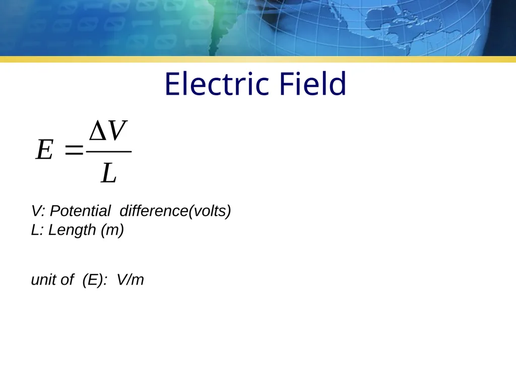
slide4. Electric Field unit of (E): V/m V: Potential difference(volts)
L: Length (m)<br>
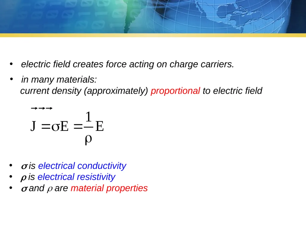
slide5. electric field creates force acting on charge carriers. in many materials:
current density (approximately) proportional to electric field is electrical conductivity
is electrical resistivity
and are material properties<br>
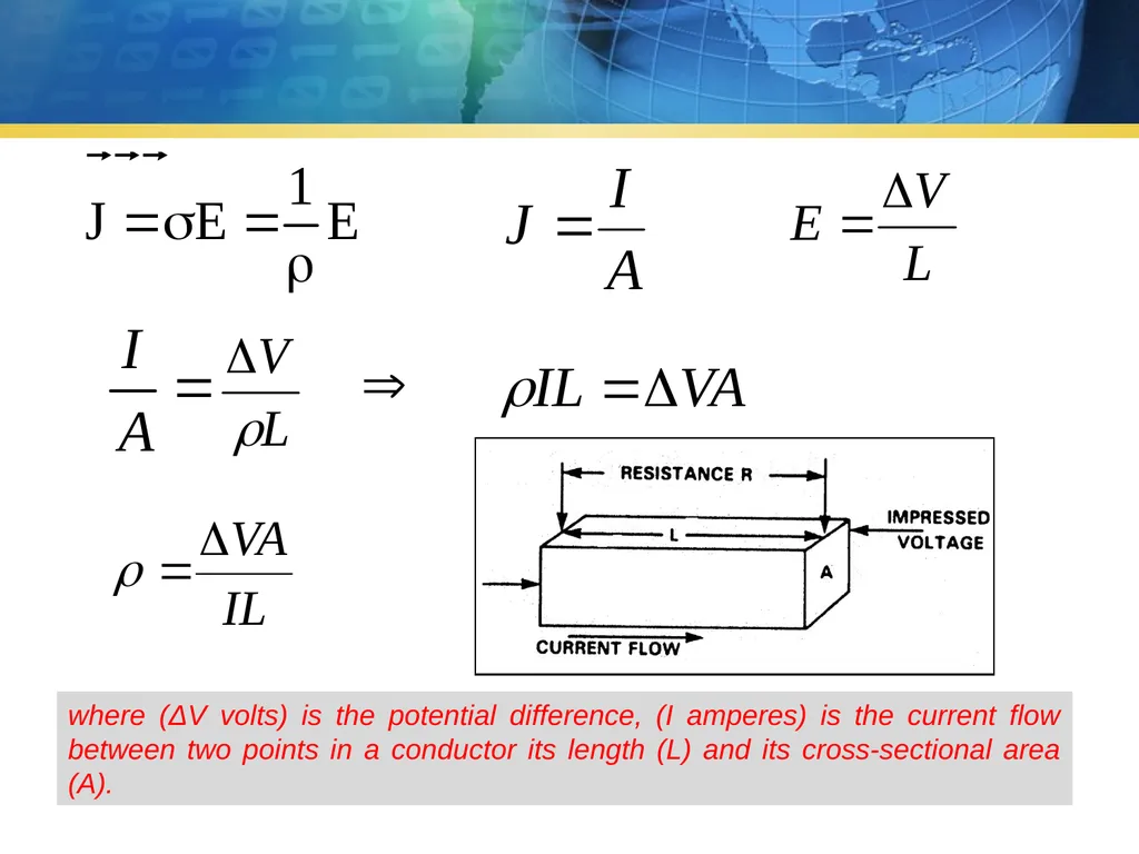
slide6. where (ΔV volts) is the potential difference, (I amperes) is the current flow between two points in a conductor its length (L) and its cross-sectional area (A).<br>
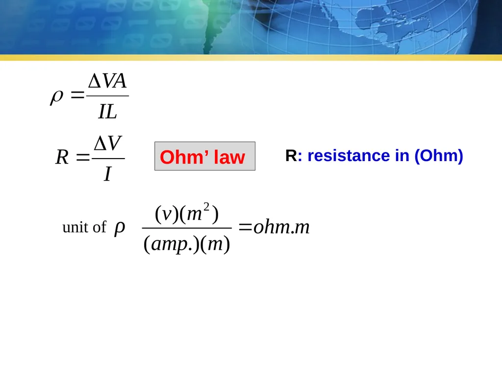
slide7. Ohm’ law R: resistance in (Ohm)<br>
slide8. The resistivity (ρ) depends on the property of the material and is a geometrically - independent quantity that describes a material’s ability to transmit electrical current.
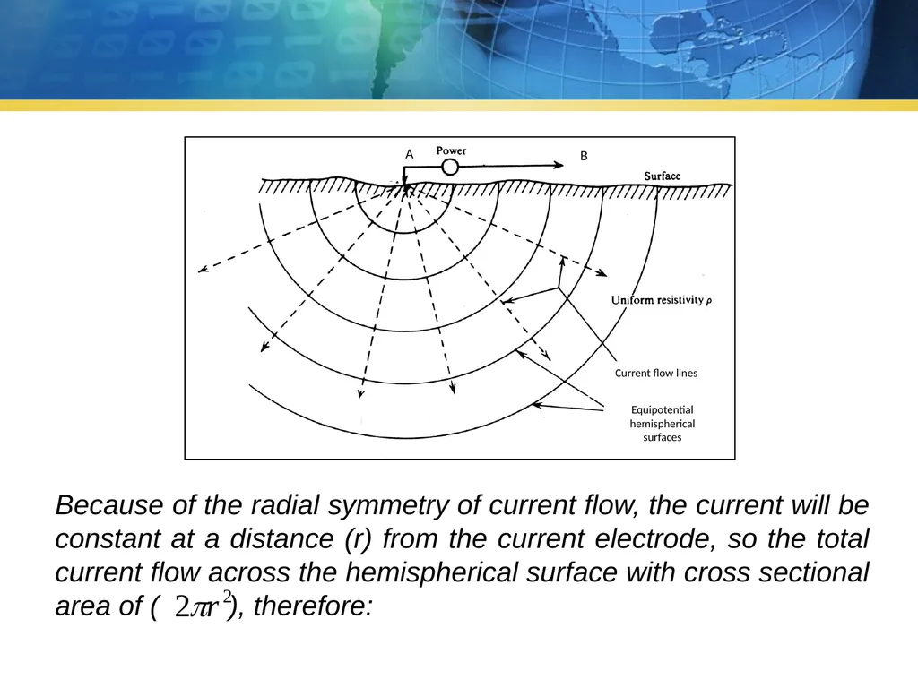
For a half space solution we consider a single current electrode, a point source of current, on the surface of a homogeneous-isotropic half space, injecting a current (I) into the Earth. The flow of electric current will be radially symmetric in the half space. We balance the current flowing into the earth at the electrode with the total current flow out of a hemispherical surface.<br>
slide9. Because of the radial symmetry of current flow, the current will be constant at a distance (r) from the current electrode, so the total current flow across the hemispherical surface with cross sectional area of ( ), therefore:<br>
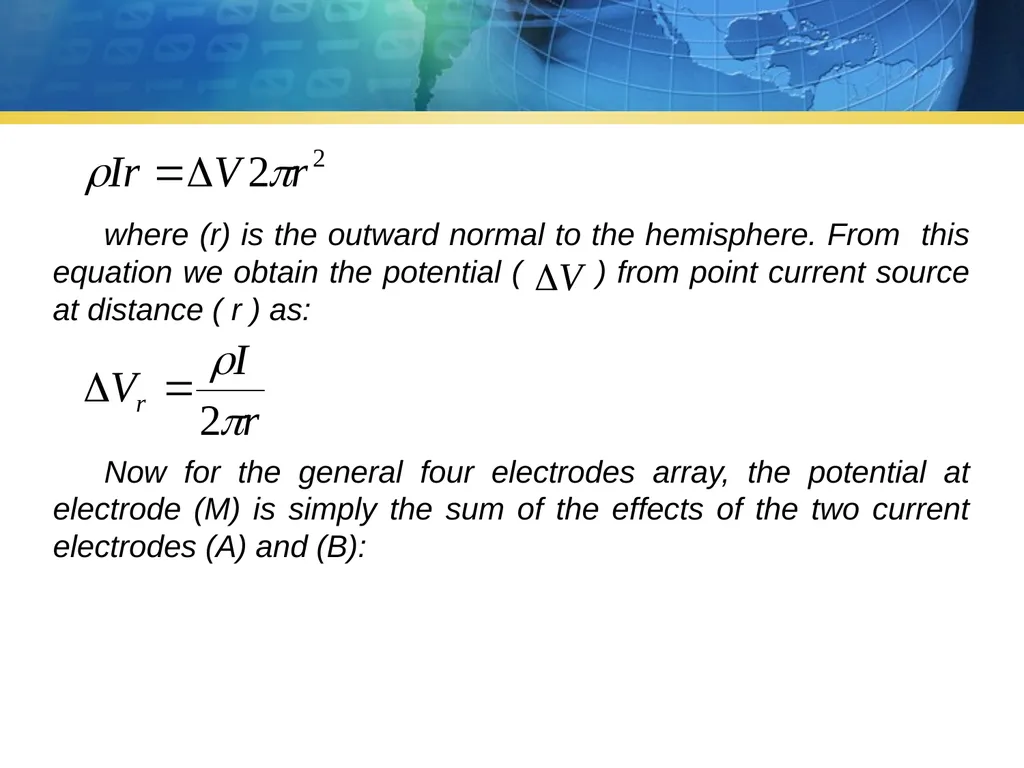
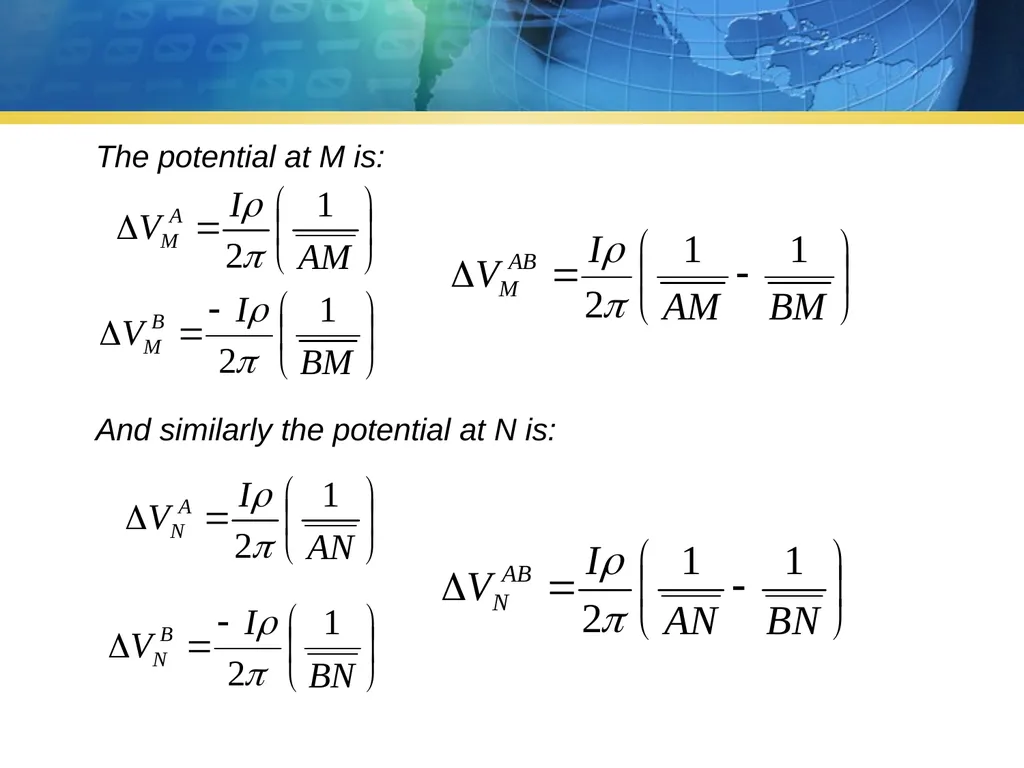
slide10. where (r) is the outward normal to the hemisphere. From this equation we obtain the potential ( ) from point current source at distance ( r ) as: Now for the general four electrodes array, the potential at electrode (M) is simply the sum of the effects of the two current electrodes (A) and (B):<br>
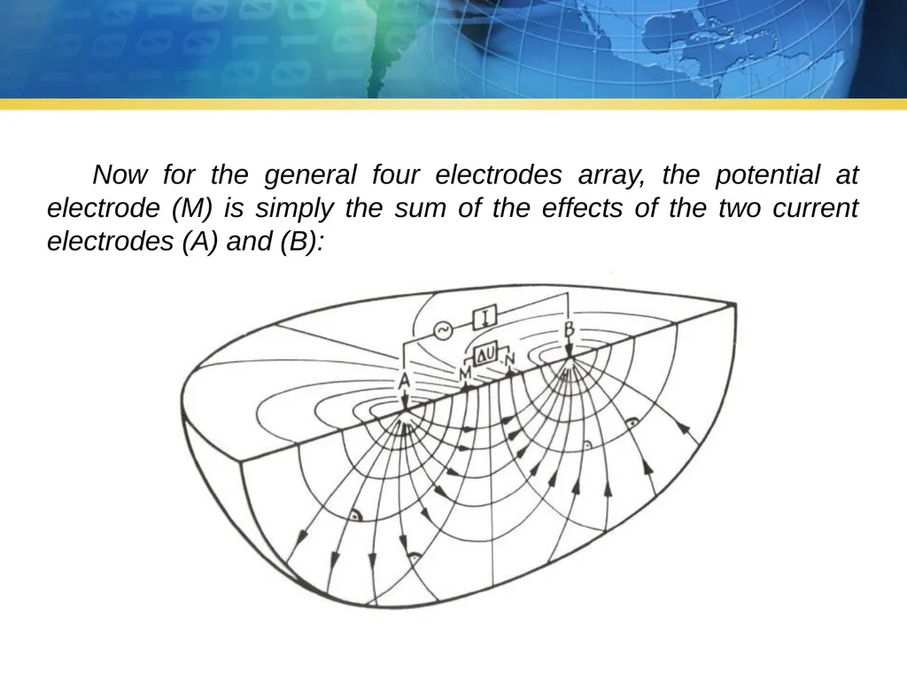
slide11. Now for the general four electrodes array, the potential at electrode (M) is simply the sum of the effects of the two current electrodes (A) and (B):<br>
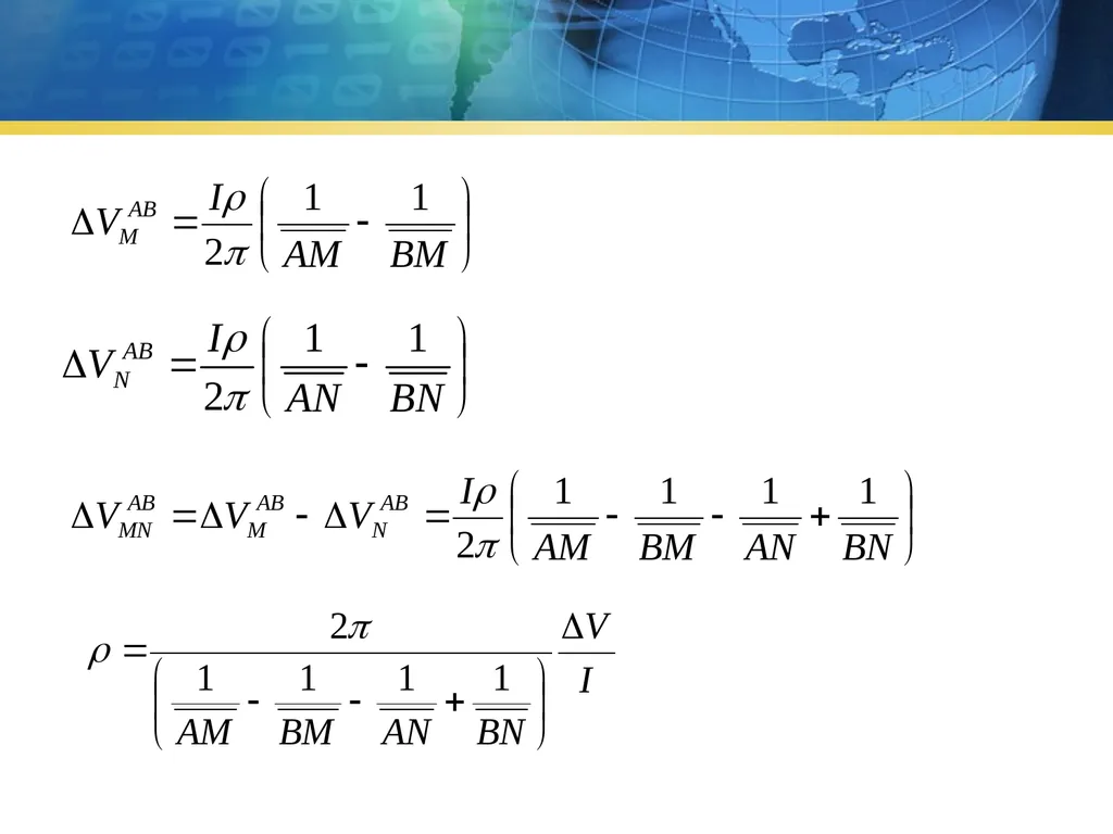
slide12. And similarly the potential at N is: The potential at M is:<br>
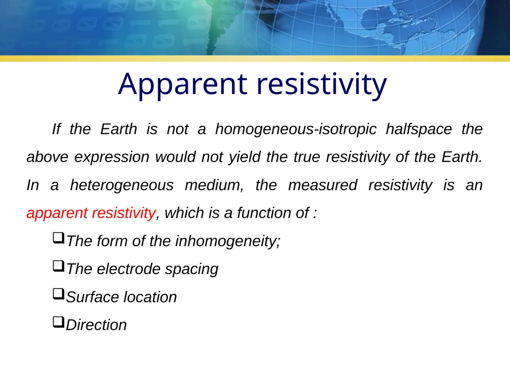
slide14. If the Earth is not a homogeneous-isotropic halfspace the above expression would not yield the true resistivity of the Earth. In a heterogeneous medium, the measured resistivity is an apparent resistivity, which is a function of :
The form of the inhomogeneity;
The electrode spacing
Surface location
Direction Apparent resistivity<br>
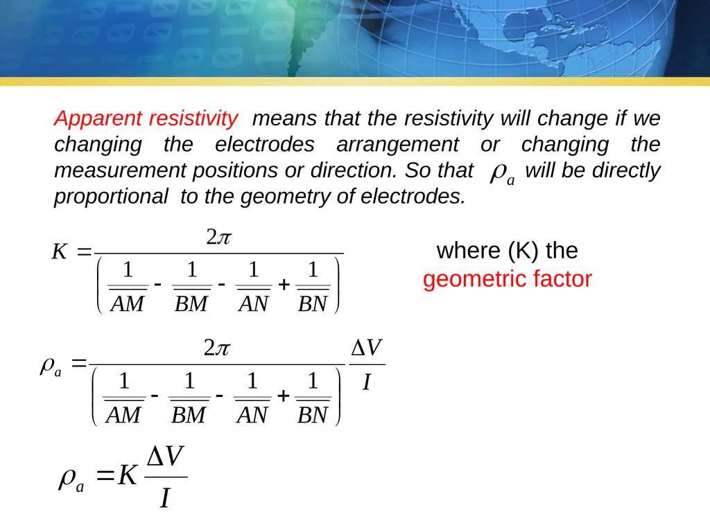
slide15. where (K) the
geometric factor Apparent resistivity means that the resistivity will change if we changing the electrodes arrangement or changing the measurement positions or direction. So that will be directly proportional to the geometry of electrodes.<br>
Dr. Firas AL-Menshed
Head of Geophysics Division
Lecture 1
Resistivity Equation Ministry of water resources
General commission for groundwater
Geophysics division<br>
slide2. The DC resistivity method is one of the simplest geophysical techniques used to measure earth resistivity, but it is still employed extensively because of its easy using and relatively easy interpretation. The most common application is groundwater exploration, but it is also used in geothermal, environmental, and engineering studies. The measurement of the earth’s resistivity is very similar in concept to the laboratory resistivity measurement of rock samples. A DC electric current is passed through the ground via a pair of current electrodes and a resulting potential difference is measured between a second pair of potential electrodes. Introduction<br>
slide3. current density (J) is current per area or, equivalently,
charge per area and time
unit of J: A/m2 directions are important … I: Current (Amperes)
A: Area (m2) Current Density<br>
slide4. Electric Field unit of (E): V/m V: Potential difference(volts)
L: Length (m)<br>
slide5. electric field creates force acting on charge carriers. in many materials:
current density (approximately) proportional to electric field is electrical conductivity
is electrical resistivity
and are material properties<br>
slide6. where (ΔV volts) is the potential difference, (I amperes) is the current flow between two points in a conductor its length (L) and its cross-sectional area (A).<br>
slide7. Ohm’ law R: resistance in (Ohm)<br>
slide8. The resistivity (ρ) depends on the property of the material and is a geometrically - independent quantity that describes a material’s ability to transmit electrical current.
For a half space solution we consider a single current electrode, a point source of current, on the surface of a homogeneous-isotropic half space, injecting a current (I) into the Earth. The flow of electric current will be radially symmetric in the half space. We balance the current flowing into the earth at the electrode with the total current flow out of a hemispherical surface.<br>
slide9. Because of the radial symmetry of current flow, the current will be constant at a distance (r) from the current electrode, so the total current flow across the hemispherical surface with cross sectional area of ( ), therefore:<br>
slide10. where (r) is the outward normal to the hemisphere. From this equation we obtain the potential ( ) from point current source at distance ( r ) as: Now for the general four electrodes array, the potential at electrode (M) is simply the sum of the effects of the two current electrodes (A) and (B):<br>
slide11. Now for the general four electrodes array, the potential at electrode (M) is simply the sum of the effects of the two current electrodes (A) and (B):<br>
slide12. And similarly the potential at N is: The potential at M is:<br>
slide14. If the Earth is not a homogeneous-isotropic halfspace the above expression would not yield the true resistivity of the Earth. In a heterogeneous medium, the measured resistivity is an apparent resistivity, which is a function of :
The form of the inhomogeneity;
The electrode spacing
Surface location
Direction Apparent resistivity<br>
slide15. where (K) the
geometric factor Apparent resistivity means that the resistivity will change if we changing the electrodes arrangement or changing the measurement positions or direction. So that will be directly proportional to the geometry of electrodes.<br>