FALSE PATH ANALYSIS AND CRITICAL PATH ANALYSIS Presented by, Deexith V False path analysis Certain timing paths are not real in the actual functional operation of the design. Such paths can be turned off during STA by setting these as false
"FALSE PATH ANALYSIS AND CRITICAL PATH ANALYSIS" is the property of its rightful owner. Permission is granted to
download and print the materials on this website for personal, non-commercial use only, and to display it
on your personal computer provided you do not modify the materials and that you retain all copyright
notices contained in the materials. By downloading content from our website, you accept the terms of this
agreement.
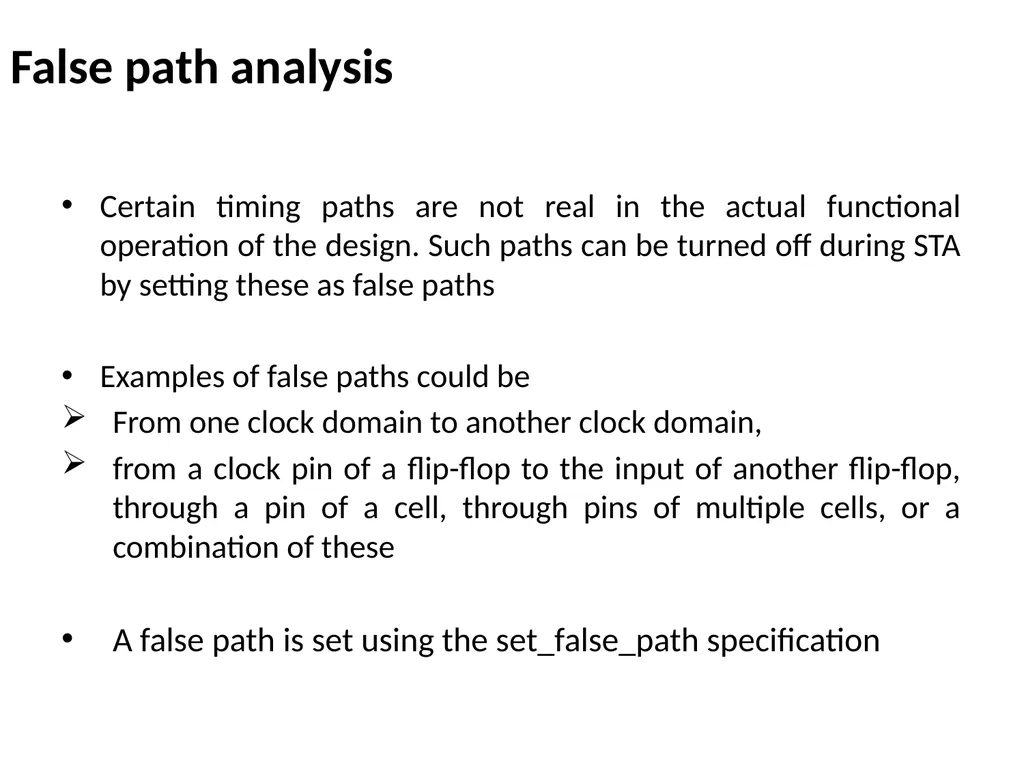
False path analysis Certain timing paths are not real in the actual functional operation of the design. Such paths can be turned off during STA by setting these as false paths
Examples of false paths could be
From one clock domain to another clock domain,
from a clock pin of a flip-flop to the input of another flip-flop, through a pin of a cell, through pins of multiple cells, or a combination of these
A false path is set using the set_false_path specification<br>
03
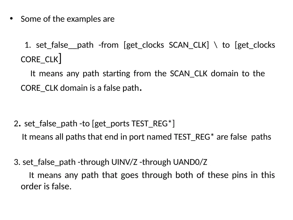
Some of the examples are
1. set_false__path -from [get_clocks SCAN_CLK] \ to [get_clocks CORE_CLK]
It means any path starting from the SCAN_CLK domain to the CORE_CLK domain is a false path.
2. set_false_path -to [get_ports TEST_REG*]
It means all paths that end in port named TEST_REG* are false paths
3. set_false_path -through UINV/Z -through UAND0/Z
It means any path that goes through both of these pins in this order is false.<br>
04
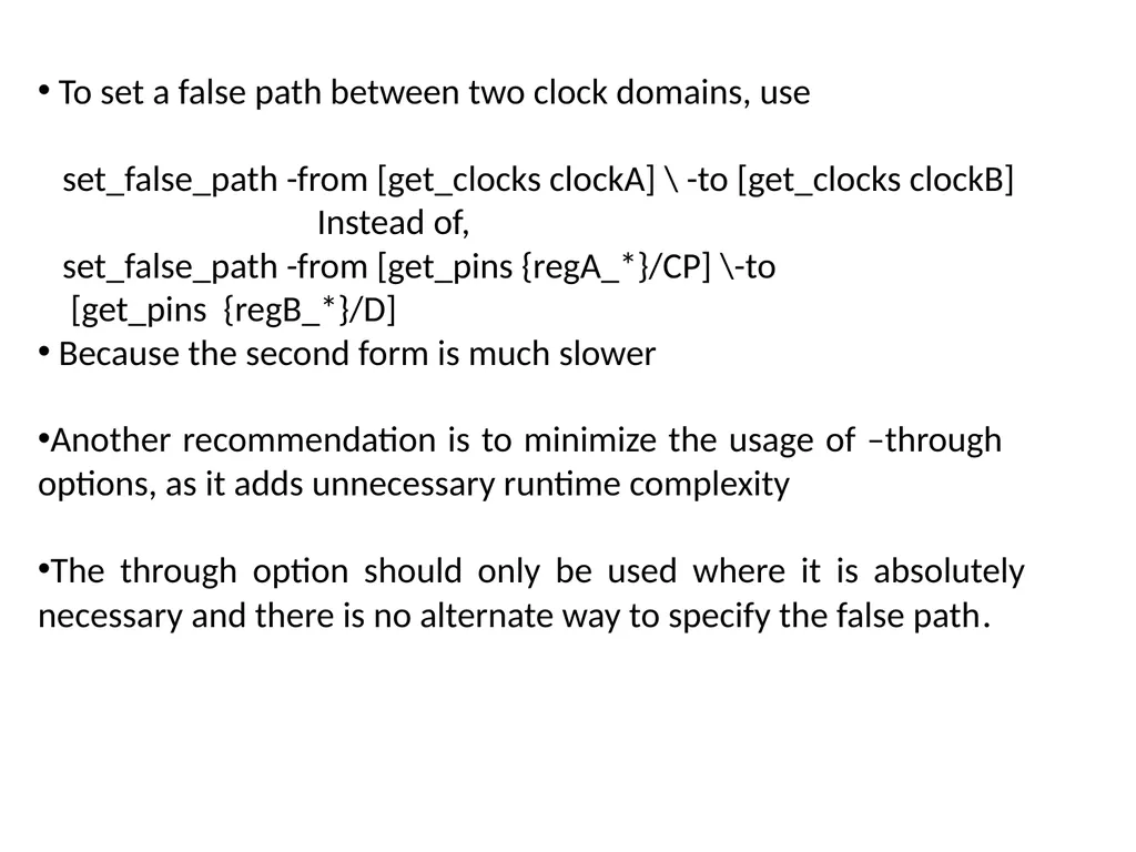
To set a false path between two clock domains, use
set_false_path -from [get_clocks clockA] \ -to [get_clocks clockB]
Instead of,
set_false_path -from [get_pins {regA_*}/CP] \-to
[get_pins {regB_*}/D]
Because the second form is much slower
Another recommendation is to minimize the usage of –through options, as it adds unnecessary runtime complexity
The through option should only be used where it is absolutely necessary and there is no alternate way to specify the false path.<br>
05
Advantages the analysis space is reduced
focus only on the real paths
Helps to cut down the analysis time as well<br>
06
Disadvantages Not to use a false path when a multi cycle path is the real intent
If a false path is used on a path that is sampled many clock cycles later, optimization of the remaining logic may invariably slow this path even beyond what may be necessary<br>
07
Critical path analysis STA is used to verify the timing of the design and can also be run prior to performing logic optimization - the goal is to identify the worst or critical timing paths
STA can be rerun after logic optimization to see whether there are failing paths still remaining that need to be optimized, or to identify the critical paths
During physical design, STA can be performed at each and every step to identify the worst paths/critical paths
At the logical design phase, ideal interconnect may be assumed since there is no physical information related to the placement; there may be more interest in viewing the logic that contributes to the worst paths<br>
08
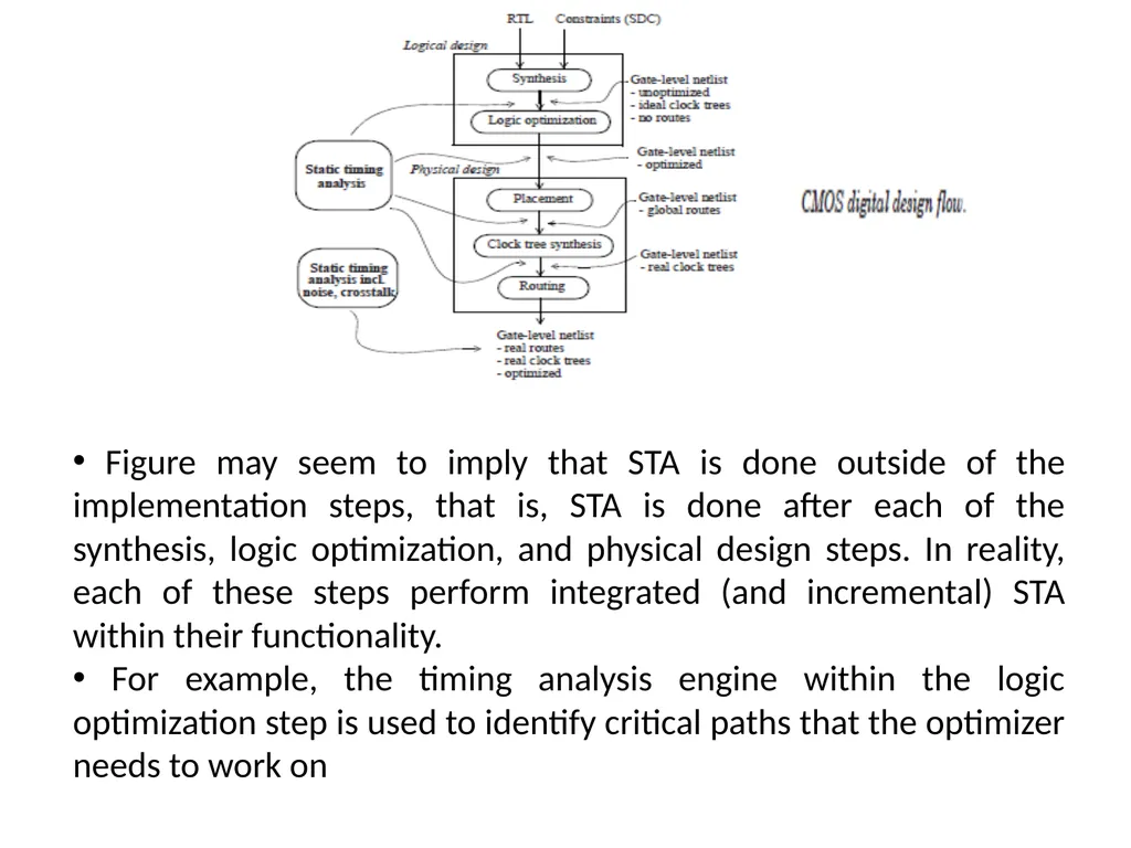
Figure may seem to imply that STA is done outside of the implementation steps, that is, STA is done after each of the synthesis, logic optimization, and physical design steps. In reality, each of these steps perform integrated (and incremental) STA within their functionality.
For example, the timing analysis engine within the logic optimization step is used to identify critical paths that the optimizer needs to work on<br>
09
Advantages Better allocation of resources
Reduces the risk of task and cost<br>
10
Disadvantages Too many activities make the network diagram too complicated<br>