
Fault-Detection, Isolation and Recovery (FDIR)
CB
Published · 15 slides · 0 views

1 / 1
Description
Fault-Detection, Isolation and Recovery (FDIR) Techniques in space: onboard autonomous decisions to obtain a safe, efficient, and maintainable system Anna Maria Di Giorgio INAF IAPS Introduction On-board Fault Detection, Isolation and
Related Topics
Share
Embed code
Download this presentation From Below
"Fault-Detection, Isolation and Recovery (FDIR)" is the property of its rightful owner. Permission is granted to download and print the materials on this website for personal, non-commercial use only, and to display it on your personal computer provided you do not modify the materials and that you retain all copyright notices contained in the materials. By downloading content from our website, you accept the terms of this agreement.
Presentation Transcript
01
Fault-Detection, Isolation and Recovery (FDIR) Techniques in space:
onboard autonomous decisions to obtain a safe, efficient, and maintainable system Anna Maria Di Giorgio
INAF IAPS<br>
onboard autonomous decisions to obtain a safe, efficient, and maintainable system Anna Maria Di Giorgio
INAF IAPS<br>
02
Introduction On-board Fault Detection, Isolation and Recovery (FDIR) systems aim at
maintaining the safe spacecraft/payload operation even when faults occur.
Limiting service interruptions with reduced ground operations.
FDIR is the means to detect off-nominal conditions, isolate the problem to a
specific subsystem/component, and recover of systems and capabilities.
FDIR is considered as an operational function that contributes to the autonomy of the system.<br>
maintaining the safe spacecraft/payload operation even when faults occur.
Limiting service interruptions with reduced ground operations.
FDIR is the means to detect off-nominal conditions, isolate the problem to a
specific subsystem/component, and recover of systems and capabilities.
FDIR is considered as an operational function that contributes to the autonomy of the system.<br>
03
Introduction A fault can be defined as an unpermitted deviation of at least one characteristic property or parameter of the system from the standard condition.
Such malfunctions may occur in sensors, actuators or other devices and affect adversely the local or global behavior of the system.
• Early detection of abnormal situations, i.e. detection delay should be minimized.
• Good ability to discriminate between different failures (isolability).
• Good robustness to various noise and uncertainties sources, and their propagation through the system.
• High sensitivity and performance, i.e. high detection rate and low false alarm rate.<br>
Such malfunctions may occur in sensors, actuators or other devices and affect adversely the local or global behavior of the system.
• Early detection of abnormal situations, i.e. detection delay should be minimized.
• Good ability to discriminate between different failures (isolability).
• Good robustness to various noise and uncertainties sources, and their propagation through the system.
• High sensitivity and performance, i.e. high detection rate and low false alarm rate.<br>
04
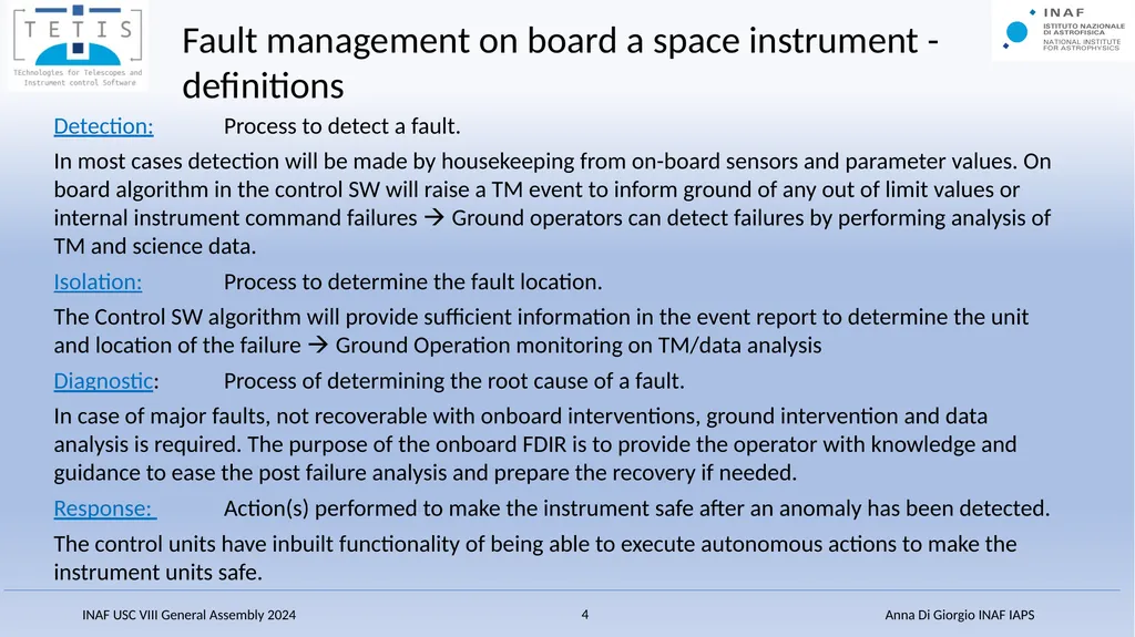
Detection: Process to detect a fault.
In most cases detection will be made by housekeeping from on-board sensors and parameter values. On board algorithm in the control SW will raise a TM event to inform ground of any out of limit values or internal instrument command failures Ground operators can detect failures by performing analysis of TM and science data.
Isolation: Process to determine the fault location.
The Control SW algorithm will provide sufficient information in the event report to determine the unit and location of the failure Ground Operation monitoring on TM/data analysis
Diagnostic: Process of determining the root cause of a fault.
In case of major faults, not recoverable with onboard interventions, ground intervention and data analysis is required. The purpose of the onboard FDIR is to provide the operator with knowledge and guidance to ease the post failure analysis and prepare the recovery if needed.
Response: Action(s) performed to make the instrument safe after an anomaly has been detected.
The control units have inbuilt functionality of being able to execute autonomous actions to make the instrument units safe. Fault management on board a space instrument - definitions<br>
In most cases detection will be made by housekeeping from on-board sensors and parameter values. On board algorithm in the control SW will raise a TM event to inform ground of any out of limit values or internal instrument command failures Ground operators can detect failures by performing analysis of TM and science data.
Isolation: Process to determine the fault location.
The Control SW algorithm will provide sufficient information in the event report to determine the unit and location of the failure Ground Operation monitoring on TM/data analysis
Diagnostic: Process of determining the root cause of a fault.
In case of major faults, not recoverable with onboard interventions, ground intervention and data analysis is required. The purpose of the onboard FDIR is to provide the operator with knowledge and guidance to ease the post failure analysis and prepare the recovery if needed.
Response: Action(s) performed to make the instrument safe after an anomaly has been detected.
The control units have inbuilt functionality of being able to execute autonomous actions to make the instrument units safe. Fault management on board a space instrument - definitions<br>
05
Top level recommendations for the fault management on board a space instrument:
All instrument subsystems shall ensure that their critical functionality and performance can be monitored; HW shall supply sensors to provide the necessary HK telemetry, whilst SW shall provide status parameters as an output of regular health checks.
All instrument subsystems shall be designed to not allow failures to propagate from one function/unit to another function/unit.
Each automatic action following failure detection shall be justified through FMEA by:
the risk of failure propagation inside the Subsystem (as propagation to the redundant function)
the risk of failure propagation to other Subsystem of the Satellite
the risk of Subsystem permanent damage leading to the loss or the degradation of the mission (such as temperature out of safety range). Fault management on board a space instrument - 1<br>
All instrument subsystems shall ensure that their critical functionality and performance can be monitored; HW shall supply sensors to provide the necessary HK telemetry, whilst SW shall provide status parameters as an output of regular health checks.
All instrument subsystems shall be designed to not allow failures to propagate from one function/unit to another function/unit.
Each automatic action following failure detection shall be justified through FMEA by:
the risk of failure propagation inside the Subsystem (as propagation to the redundant function)
the risk of failure propagation to other Subsystem of the Satellite
the risk of Subsystem permanent damage leading to the loss or the degradation of the mission (such as temperature out of safety range). Fault management on board a space instrument - 1<br>
06
The instrument shall be set-up for self-monitoring by the internal Control Unit. However, the spacecraft will also be responsible for higher level monitoring activities
In case of any relevant fault conditions, external to the instrument, the S/C shall command the Instrument Control SW to perform a mode transition to a safe mode (including a possible power off of the whole instrument).
The S/C shall monitor the various S/C temperature sensors which are located throughout the PLM and SVM and ensure that the instrument I/F temperatures remain within their operational or non-operational limits depending on the operating mode.
In the case that the Instrument is in a safe mode, it shall be the S/C responsibility to ensure the survival heaters are activated (if necessary) to keep all sub-units within their non-operational temperature limits.
If the S/C loses communication with the Instrument Control Unit
not possible to continue with science operations
the S/C should remove the primary power from the unit.
The power to the Control Unit and to other (not all) sub-units is under the control of the S/C
if the instrument level FDIR requires a sub-unit switch off, the Control SW sends request to S/C for power to be removed from the other sub-unit. The Spacecraft role in the instrument FDIR actuation<br>
In case of any relevant fault conditions, external to the instrument, the S/C shall command the Instrument Control SW to perform a mode transition to a safe mode (including a possible power off of the whole instrument).
The S/C shall monitor the various S/C temperature sensors which are located throughout the PLM and SVM and ensure that the instrument I/F temperatures remain within their operational or non-operational limits depending on the operating mode.
In the case that the Instrument is in a safe mode, it shall be the S/C responsibility to ensure the survival heaters are activated (if necessary) to keep all sub-units within their non-operational temperature limits.
If the S/C loses communication with the Instrument Control Unit
not possible to continue with science operations
the S/C should remove the primary power from the unit.
The power to the Control Unit and to other (not all) sub-units is under the control of the S/C
if the instrument level FDIR requires a sub-unit switch off, the Control SW sends request to S/C for power to be removed from the other sub-unit. The Spacecraft role in the instrument FDIR actuation<br>
07
In the case of a confirmed out-of-limit of critical HK parameters related to the Focal Plan arrays/electronics, the first preference would be for the Control SW to request that only the power of the relevant unit is turned off, keeping all other (if any) FPA units on and able to carry on science acquisition. This will allow to remain in the science acquisition mode and continue with the pre-loaded operations sequence in an “degraded” Science operations mode.
For situations where simply powering off one of the subsystems is not sufficient to continue performing science operations successfully and safely and where the subsystems safety may be at risk, the Control SW shall place the instrument into one of the defined a safe modes. In these modes the instrument will no longer execute any of its pre-loaded sequences nor accept new ones ground intervention is needed
In the event that it is not safe for even the Control Unit to remain on (not a preferred situation due to the loss of internal instrument monitoring), which may be either due to a Control Unit failure or a serious external failure, the Control SW will initiate the switch-off of all instrument sub-units followed by the S/C gracefully powering off the Control unit itself. Science operations priorities<br>
For situations where simply powering off one of the subsystems is not sufficient to continue performing science operations successfully and safely and where the subsystems safety may be at risk, the Control SW shall place the instrument into one of the defined a safe modes. In these modes the instrument will no longer execute any of its pre-loaded sequences nor accept new ones ground intervention is needed
In the event that it is not safe for even the Control Unit to remain on (not a preferred situation due to the loss of internal instrument monitoring), which may be either due to a Control Unit failure or a serious external failure, the Control SW will initiate the switch-off of all instrument sub-units followed by the S/C gracefully powering off the Control unit itself. Science operations priorities<br>
08
Different approaches, depending on the redundancy architecture adopted onboard.
Cold redundancy: redundancy where one entity is operating and the others are powered off. In this case any autonomous reconfiguration shall not be performed onboard. In the event that such reconfiguration is necessary, it must be identified upon subsequent passage to the ground and initiated manually from the ground
Hot redundancy: redundancy entity is 'ON', but not necessarily in the right configuration to accomplish the function possibility of autonomous reconfigurations
Examples:
Euclid VIS : cold redundancy HW architecture at instrument level: nominal control system nominal mechanism control unit focal Plane Arrays
PLATO: nominal control system can command/activate redundant subsystems (internal cross strapping) Autonomous reconfigurations to redundant branches<br>
Cold redundancy: redundancy where one entity is operating and the others are powered off. In this case any autonomous reconfiguration shall not be performed onboard. In the event that such reconfiguration is necessary, it must be identified upon subsequent passage to the ground and initiated manually from the ground
Hot redundancy: redundancy entity is 'ON', but not necessarily in the right configuration to accomplish the function possibility of autonomous reconfigurations
Examples:
Euclid VIS : cold redundancy HW architecture at instrument level: nominal control system nominal mechanism control unit focal Plane Arrays
PLATO: nominal control system can command/activate redundant subsystems (internal cross strapping) Autonomous reconfigurations to redundant branches<br>
09
Depending on the complexity of the different FDIR procedures to be implemented onboard, different approaches to their implementation can be adopted:
use procedures “hardcoded” in the application SW: same language, compiled with the rest of the code:
once fixed they cannot be changed (even a minor change require an OBS patch)
Usable only in case of limited timing constraints in commanding
“easy” to validate
embed into the code an “interpreter” to execute procedures that can be uploaded as tables
Procedures can be changed on-ground and updated without any need of SW patches
Can help in case of severe timing constraints in commanding
Procedure validation on-ground is critical 18/06/2019 ARIEL Consortium meeting – Warsaw CBK 9<br>
use procedures “hardcoded” in the application SW: same language, compiled with the rest of the code:
once fixed they cannot be changed (even a minor change require an OBS patch)
Usable only in case of limited timing constraints in commanding
“easy” to validate
embed into the code an “interpreter” to execute procedures that can be uploaded as tables
Procedures can be changed on-ground and updated without any need of SW patches
Can help in case of severe timing constraints in commanding
Procedure validation on-ground is critical 18/06/2019 ARIEL Consortium meeting – Warsaw CBK 9<br>
10
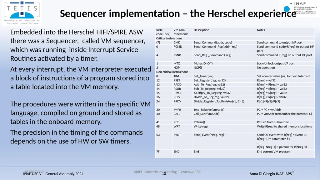
Embedded into the Herschel HIFI/SPIRE ASW there was a Sequencer, called VM sequencer, which was running inside Interrupt Service Routines activated by a timer.
At every interrupt, the VM interpreter executed a block of instructions of a program stored into a table located into the VM memory.
The procedures were written in the specific VM language, compiled on ground and stored as tables in the onboard memory.
The precision in the timing of the commands depends on the use of HW or SW timers. 18/06/2019 ARIEL Consortium meeting – Warsaw CBK 10 Sequencer implementation – the Herschel experience<br>
At every interrupt, the VM interpreter executed a block of instructions of a program stored into a table located into the VM memory.
The procedures were written in the specific VM language, compiled on ground and stored as tables in the onboard memory.
The precision in the timing of the commands depends on the use of HW or SW timers. 18/06/2019 ARIEL Consortium meeting – Warsaw CBK 10 Sequencer implementation – the Herschel experience<br>
11
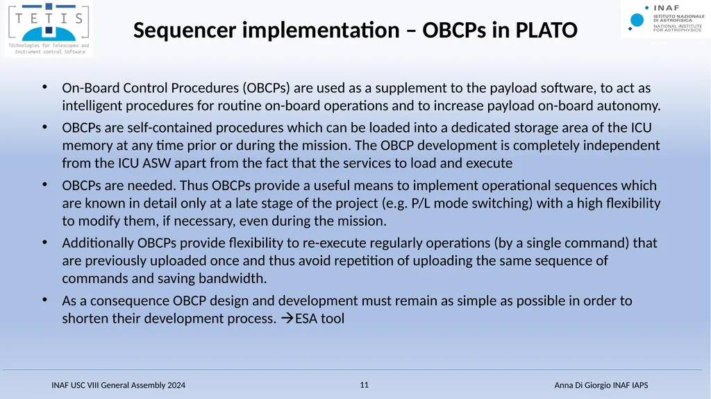
On-Board Control Procedures (OBCPs) are used as a supplement to the payload software, to act as intelligent procedures for routine on-board operations and to increase payload on-board autonomy.
OBCPs are self-contained procedures which can be loaded into a dedicated storage area of the ICU memory at any time prior or during the mission. The OBCP development is completely independent from the ICU ASW apart from the fact that the services to load and execute
OBCPs are needed. Thus OBCPs provide a useful means to implement operational sequences which are known in detail only at a late stage of the project (e.g. P/L mode switching) with a high flexibility to modify them, if necessary, even during the mission.
Additionally OBCPs provide flexibility to re-execute regularly operations (by a single command) that are previously uploaded once and thus avoid repetition of uploading the same sequence of commands and saving bandwidth.
As a consequence OBCP design and development must remain as simple as possible in order to shorten their development process. ESA tool Sequencer implementation – OBCPs in PLATO<br>
OBCPs are self-contained procedures which can be loaded into a dedicated storage area of the ICU memory at any time prior or during the mission. The OBCP development is completely independent from the ICU ASW apart from the fact that the services to load and execute
OBCPs are needed. Thus OBCPs provide a useful means to implement operational sequences which are known in detail only at a late stage of the project (e.g. P/L mode switching) with a high flexibility to modify them, if necessary, even during the mission.
Additionally OBCPs provide flexibility to re-execute regularly operations (by a single command) that are previously uploaded once and thus avoid repetition of uploading the same sequence of commands and saving bandwidth.
As a consequence OBCP design and development must remain as simple as possible in order to shorten their development process. ESA tool Sequencer implementation – OBCPs in PLATO<br>
12
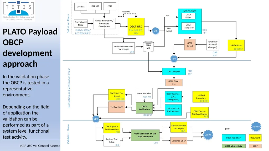
PLATO Payload OBCP development approach In the validation phase the OBCP is tested in a representative environment.
Depending on the field of application the validation can be performed as part of a system level functional test activity.<br>
Depending on the field of application the validation can be performed as part of a system level functional test activity.<br>
13
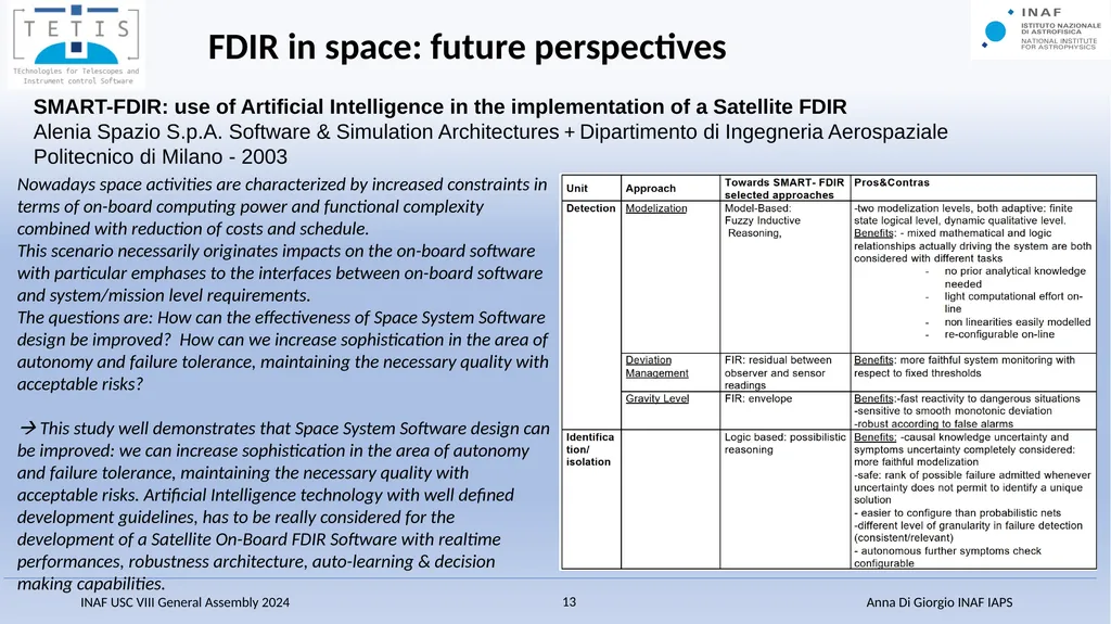
FDIR in space: future perspectives SMART-FDIR: use of Artificial Intelligence in the implementation of a Satellite FDIR
Alenia Spazio S.p.A. Software & Simulation Architectures + Dipartimento di Ingegneria Aerospaziale Politecnico di Milano - 2003 Nowadays space activities are characterized by increased constraints in terms of on-board computing power and functional complexity combined with reduction of costs and schedule.
This scenario necessarily originates impacts on the on-board software with particular emphases to the interfaces between on-board software and system/mission level requirements.
The questions are: How can the effectiveness of Space System Software design be improved? How can we increase sophistication in the area of autonomy and failure tolerance, maintaining the necessary quality with acceptable risks?
This study well demonstrates that Space System Software design can be improved: we can increase sophistication in the area of autonomy and failure tolerance, maintaining the necessary quality with acceptable risks. Artificial Intelligence technology with well defined development guidelines, has to be really considered for the development of a Satellite On-Board FDIR Software with realtime performances, robustness architecture, auto-learning & decision making capabilities.<br>
Alenia Spazio S.p.A. Software & Simulation Architectures + Dipartimento di Ingegneria Aerospaziale Politecnico di Milano - 2003 Nowadays space activities are characterized by increased constraints in terms of on-board computing power and functional complexity combined with reduction of costs and schedule.
This scenario necessarily originates impacts on the on-board software with particular emphases to the interfaces between on-board software and system/mission level requirements.
The questions are: How can the effectiveness of Space System Software design be improved? How can we increase sophistication in the area of autonomy and failure tolerance, maintaining the necessary quality with acceptable risks?
This study well demonstrates that Space System Software design can be improved: we can increase sophistication in the area of autonomy and failure tolerance, maintaining the necessary quality with acceptable risks. Artificial Intelligence technology with well defined development guidelines, has to be really considered for the development of a Satellite On-Board FDIR Software with realtime performances, robustness architecture, auto-learning & decision making capabilities.<br>
14
FDIR in space: future perspectives Health-AI
On-Board Health Monitoring System For Satcom Objectives
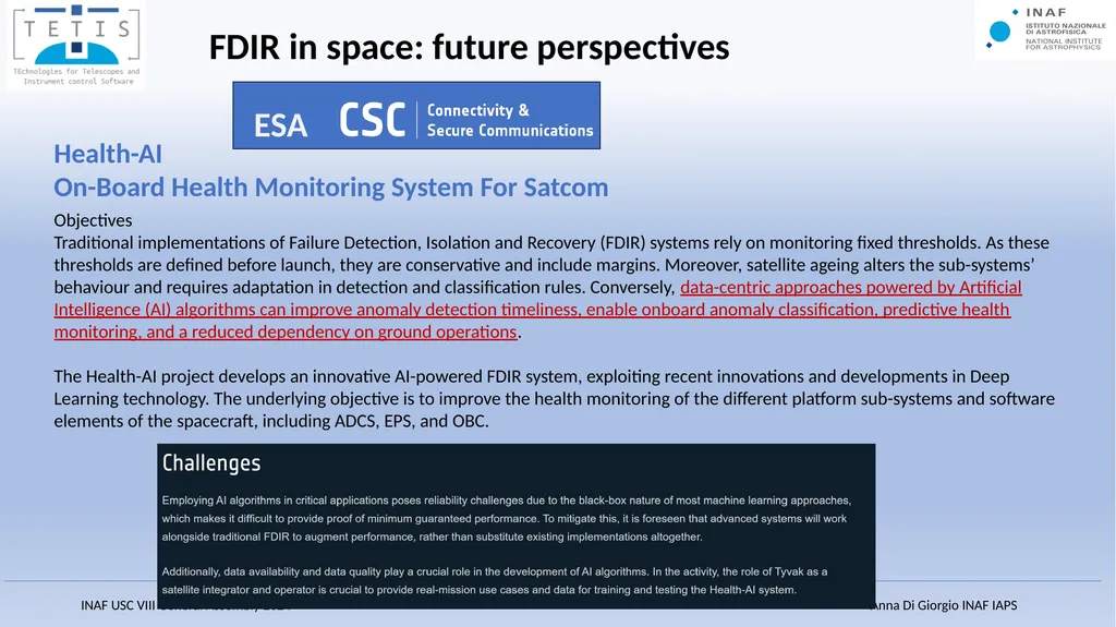
Traditional implementations of Failure Detection, Isolation and Recovery (FDIR) systems rely on monitoring fixed thresholds. As these thresholds are defined before launch, they are conservative and include margins. Moreover, satellite ageing alters the sub-systems’ behaviour and requires adaptation in detection and classification rules. Conversely, data-centric approaches powered by Artificial Intelligence (AI) algorithms can improve anomaly detection timeliness, enable onboard anomaly classification, predictive health monitoring, and a reduced dependency on ground operations.
The Health-AI project develops an innovative AI-powered FDIR system, exploiting recent innovations and developments in Deep Learning technology. The underlying objective is to improve the health monitoring of the different platform sub-systems and software elements of the spacecraft, including ADCS, EPS, and OBC. ESA<br>
On-Board Health Monitoring System For Satcom Objectives
Traditional implementations of Failure Detection, Isolation and Recovery (FDIR) systems rely on monitoring fixed thresholds. As these thresholds are defined before launch, they are conservative and include margins. Moreover, satellite ageing alters the sub-systems’ behaviour and requires adaptation in detection and classification rules. Conversely, data-centric approaches powered by Artificial Intelligence (AI) algorithms can improve anomaly detection timeliness, enable onboard anomaly classification, predictive health monitoring, and a reduced dependency on ground operations.
The Health-AI project develops an innovative AI-powered FDIR system, exploiting recent innovations and developments in Deep Learning technology. The underlying objective is to improve the health monitoring of the different platform sub-systems and software elements of the spacecraft, including ADCS, EPS, and OBC. ESA<br>
15
Health-AI
On-Board Health Monitoring System For Satcom<br>
On-Board Health Monitoring System For Satcom<br>