
Garden Box Design Plans Garden Box Materials List
TD
Published · 11 slides · 0 views

1 / 1

Description
Garden Box Design Plans Garden Box Materials List QTY (Lumber) 2 2x4x120(10) - Cut one of these boards into two 41 pieces and two 17 pieces. Cut the other board into seven 17 pieces. 7 2x4x96(8) Cut four of these boards at
Related Topics
Share
Embed code
Download this presentation From Below
"Garden Box Design Plans Garden Box Materials List" is the property of its rightful owner. Permission is granted to download and print the materials on this website for personal, non-commercial use only, and to display it on your personal computer provided you do not modify the materials and that you retain all copyright notices contained in the materials. By downloading content from our website, you accept the terms of this agreement.
Presentation Transcript
01
Garden Box Design Plans<br>
02
Garden Box Materials List QTY (Lumber)*
2 @ 2”x4”x120”(10’) - Cut one of these boards into two 41” pieces and two 17” pieces. Cut the other board into seven 17” pieces.
7 @ 2”x4”x96”(8’) – Cut four of these boards at 96”. Cut one into two 41” pieces. Cut one into one 48” piece and two 17” pieces or two 18 ½” pieces. Cut one into five 17” pieces or four 17” pieces and one 18 ½” piece. ( the three 18 ½” are for toolbox assembly).
2 @ 2”x6”x120”(10’) – Cut both boards at 100”. For a neater finish angle cuts at 45° can be used on the ends. This will require the
1 @ 2”x6”x96”(8’) – Cut this board into two 41” pieces. short board(s) to be cut at 52”. Adjustments to materials should be considered.**
6 @ 1”x4”x120”(10’)or 1”x6”x120”(10’) – Cut four of these boards at 99”. The remaining boards from these cuts will be cut into four 20 ½” pieces. Cut the other two boards into four 51” pieces, two from each board.
9 @ 1”x6”x120”(10’) Tongue and Groove – Cut these boards into fifty-four 20” pieces.
QTY (Fasteners)***
112 @ 2 ½“ wood screw (+6 for toolbox assembly) QTY based on two fasteners per assembly point.
288 @ 1 ½” wood screw ( -6 for toolbox assembly)
Hinges will be required for assembly with built in toolbox. Locking latch is optional as per builders preference.
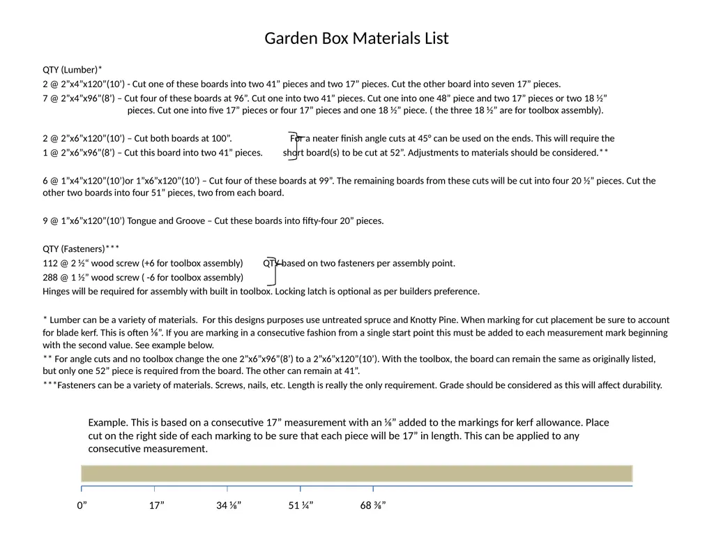
* Lumber can be a variety of materials. For this designs purposes use untreated spruce and Knotty Pine. When marking for cut placement be sure to account for blade kerf. This is often ⅛”. If you are marking in a consecutive fashion from a single start point this must be added to each measurement mark beginning with the second value. See example below.
** For angle cuts and no toolbox change the one 2”x6”x96”(8’) to a 2”x6”x120”(10’). With the toolbox, the board can remain the same as originally listed, but only one 52” piece is required from the board. The other can remain at 41”.
***Fasteners can be a variety of materials. Screws, nails, etc. Length is really the only requirement. Grade should be considered as this will affect durability. Example. This is based on a consecutive 17” measurement with an ⅛” added to the markings for kerf allowance. Place cut on the right side of each marking to be sure that each piece will be 17” in length. This can be applied to any consecutive measurement.<br>
03
Fig. 3
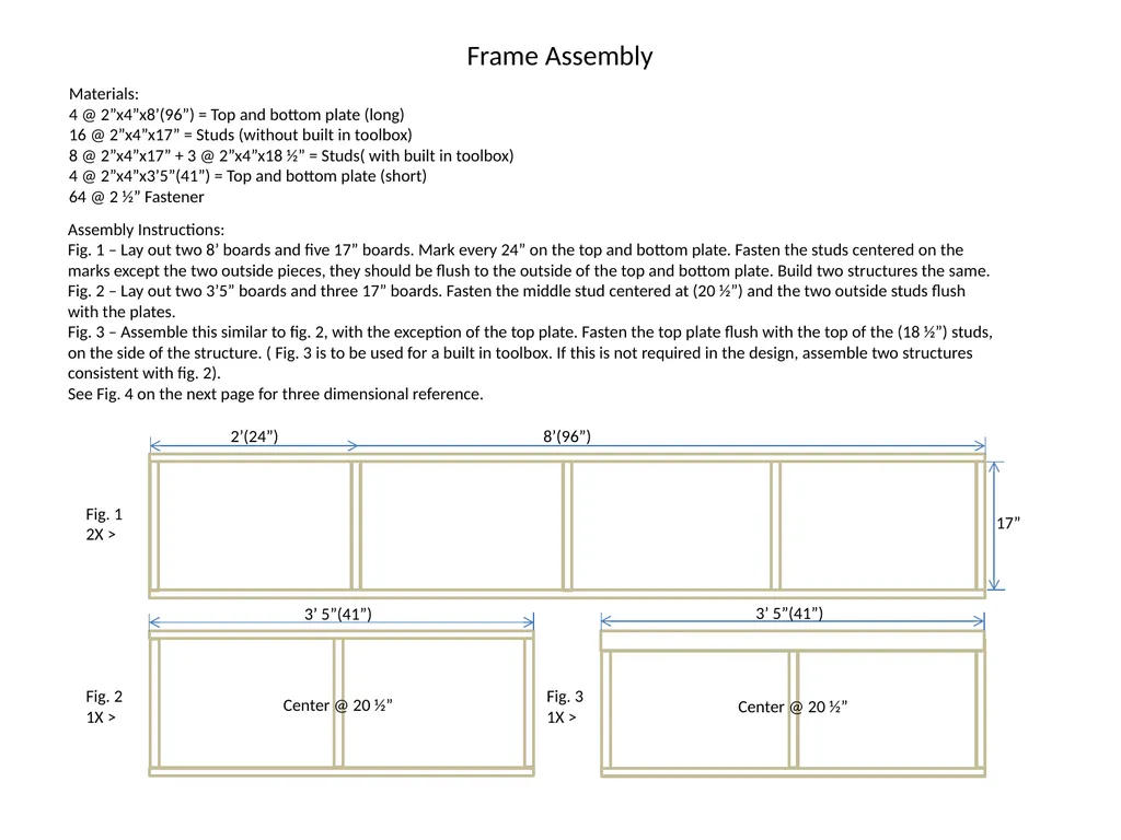
1X > Center @ 20 ½” Frame Assembly Materials:
4 @ 2”x4”x8’(96”) = Top and bottom plate (long)
16 @ 2”x4”x17” = Studs (without built in toolbox)
8 @ 2”x4”x17” + 3 @ 2”x4”x18 ½” = Studs( with built in toolbox)
4 @ 2”x4”x3’5”(41”) = Top and bottom plate (short)
64 @ 2 ½” Fastener Assembly Instructions:
Fig. 1 – Lay out two 8’ boards and five 17” boards. Mark every 24” on the top and bottom plate. Fasten the studs centered on the marks except the two outside pieces, they should be flush to the outside of the top and bottom plate. Build two structures the same.
Fig. 2 – Lay out two 3’5” boards and three 17” boards. Fasten the middle stud centered at (20 ½”) and the two outside studs flush with the plates.
Fig. 3 – Assemble this similar to fig. 2, with the exception of the top plate. Fasten the top plate flush with the top of the (18 ½”) studs, on the side of the structure. ( Fig. 3 is to be used for a built in toolbox. If this is not required in the design, assemble two structures consistent with fig. 2).
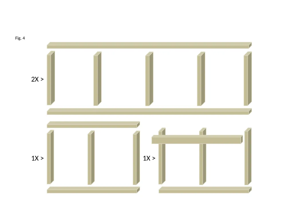
See Fig. 4 on the next page for three dimensional reference.<br>
04
Frame Assembly Con’t. Materials:
2 @ 96”x 20” Frame assembly walls
2 @ 41”x 20” Frame assembly walls
1 @ 2”x4”x48” Brace board
20 @ 2 ½” Fasteners
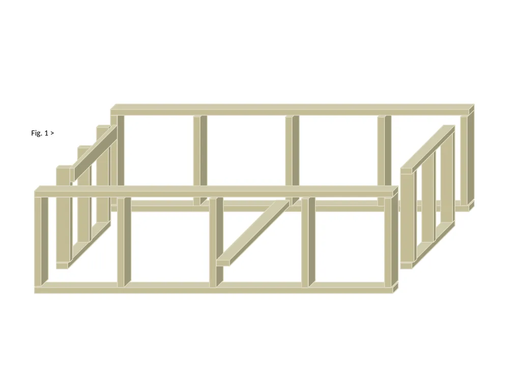
Assembly Instructions: (reference Fig. 1 on the following page.)
Stand one long wall structure perpendicular to a short wall structure. Make sure the outside edges are flush. Fasten the two structures together, with four 2 ½” fasteners, from the inside of the stud in the short wall into the edge of the outside stud of the long wall. Fastener placement should be top, center and bottom.
Stand the second short wall perpendicular to the long wall an the opposite end. Make sure outside edges are flush. Fasten the two structures together, with four 2 ½” fasteners, from the inside of the stud in the short wall into the edge of the outside stud of the long wall. Fastener placement should be top, center and bottom. (If the assembly is to be built with a toolbox, make sure that the side mounted top plate of the short wall is located at the top and to the inside of the box.
Stand the second long wall parallel to the first on the opposite side of the short wall structures. Make sure the outside edges are flush. Fasten the two structures together, with eight 2 ½” fasteners using four on each side, from the inside of the stud in the short wall into the edge of the outside stud of the long wall. This should complete the box structure.
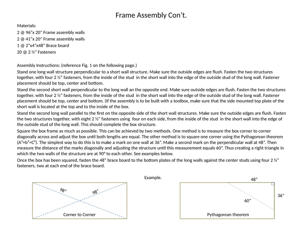
Square the box frame as much as possible. This can be achieved by two methods. One method is to measure the box corner to corner diagonally across and adjust the box until both lengths are equal. The other method is to square one corner using the Pythagorean theorem (A²+b²=C²). The simplest way to do this is to make a mark on one wall at 36”. Make a second mark on the perpendicular wall at 48”. Then measure the distance of the marks diagonally and adjusting the structure until this measurement equals 60”. Thus creating a right triangle in which the two walls of the structure are at 90° to each other. See examples below.
Once the box has been squared, fasten the 48” brace board to the bottom plates of the long walls against the center studs using four 2 ½” fasteners, two at each end of the brace board. Corner to Corner Pythagorean theorem 48” 36” 60” 98” 98” Example.<br>
05
Fig. 1 ><br>
06
Cap Assembly Materials:
2 @ 2”x6”x100” Long cap board
2 @ 2”x6”x41” Short cap board*
28 @ 2 ½” Fasteners
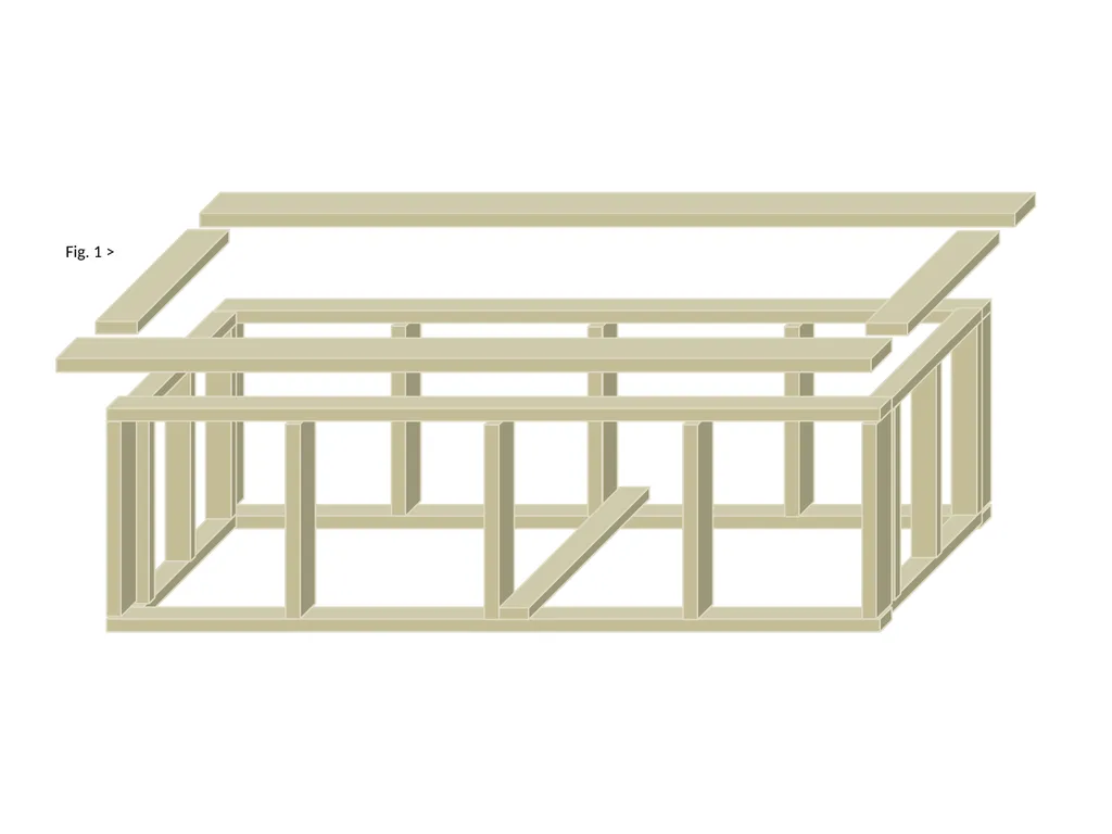
Assembly Instructions: (reference Fig. 1 on the following page.)
Position one of the long cap boards on the top of the box frame so that it is flush with the inside of the top plate (this will provide a 2” overhang along the outer edge of the box. Center the cap so that there is 5 ½” overhang on both ends. Fasten the cap to the frame using eight 2 ½” fasteners. Fastener placement should be evenly spaced along the length of the board.
Assemble the second long cap board using the same method as the first. Make sure there is 41” between the two long cap boards to accommodate the short cap boards.
Position one of the short cap boards on the top of the box frame between the two long cap boards. Make sure it is flush with the inside of the top plate (this will provide a 2” overhang along the outside edge of the box. Fasten the cap to the frame using six 2 ½” fasteners. Fastener placement should be evenly spaced along the length of the cap board.
Assemble the second short cap board using the same method as the first. If a built in toolbox is part of the design. Do not fasten the second cap board until the final stage of the build.
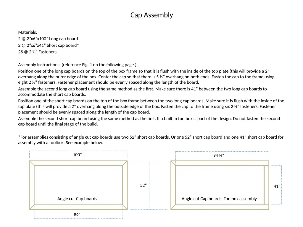
*For assemblies consisting of angle cut cap boards use two 52” short cap boards. Or one 52” short cap board and one 41” short cap board for assembly with a toolbox. See example below.<br>
07
Fig. 1 ><br>
08
Siding and Trim Assembly Materials:
4 @ 1”x4”x99” or 1”x6”x99” Long trim board
4 @ 1”x4”x51” or 1”x6”x51” Short trim board
54 @ 1”x6”x20” Siding tongue and groove
4 @ 1”x4”x20 ½” or 1”x6”x20 ½” backing board
288 @ 1 ½” Fasteners*
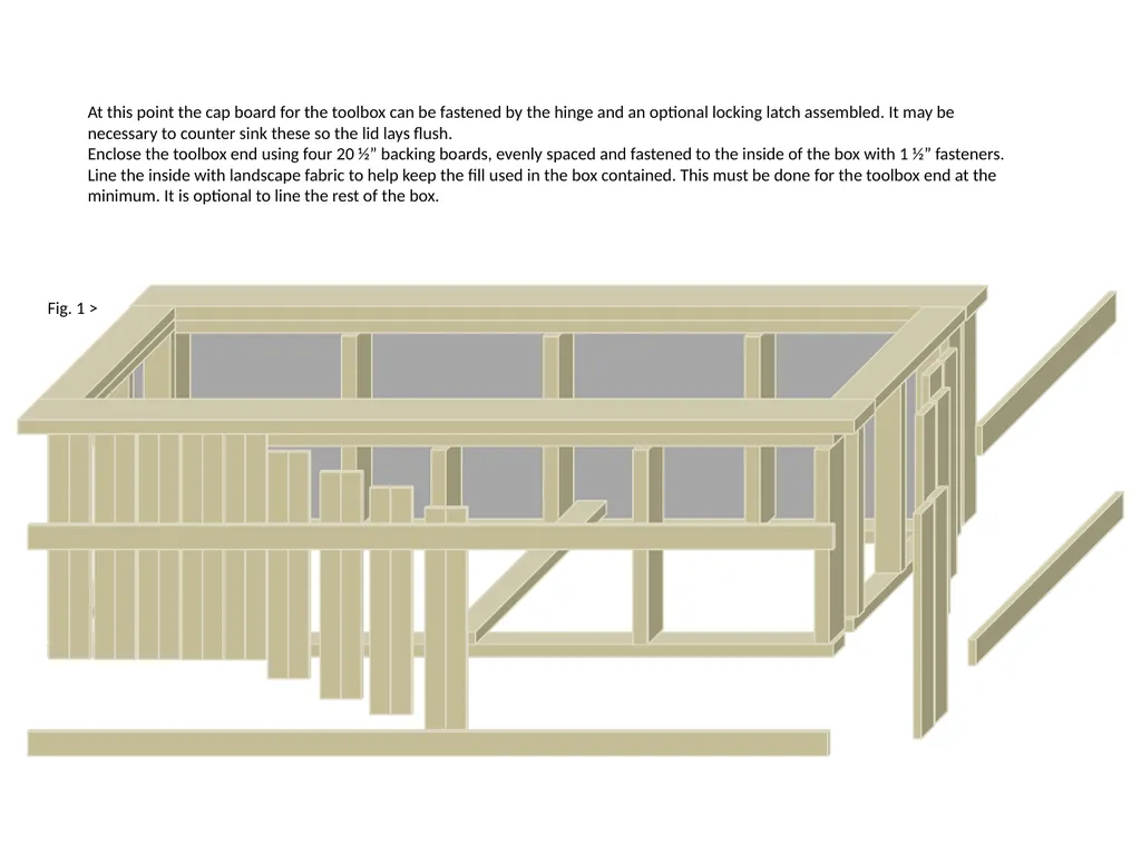
Assembly Instructions: (reference Fig. 1 on the following page.)
Cut at a 45° along the length of the siding to remove the groove side of four 20” siding boards. This will create a straight edge to flush the outsides of the box. It does not matter which side is covered first.
Begin assembly by flushing the inside of one of the angle cut siding pieces with the outside of the box frame. This will provide a ¾” overhang that the siding from an adjacent wall will flush to. Use four 1 ½” fasteners on each piece of siding. Two at the top and two at the bottom.
Consecutively fasten siding boards along the outside of the box frame by placing the groove over the tongue of the previous board, adjusting for square and fastening.
Once the end of a wall is reached, place the last board, square it and mark it the length of the siding along the edge of the frame. This will give you a reference for angle cutting the board at a 45° to finish the side and flush to the adjacent side. Be sure to cut out from this mark to provide a ¾” overhang. Continue these methods until the box is completely sided.
Cut a 45° angle into the end of all the trim boards. Be careful not to shorten the boards beyond their intended length. This will create a ¾” overhang outside the siding on all ends.
Fasten the four long trim boards to the siding. Two at the top and two at the bottom. Using eight 1 ½” fasteners evenly spaced for each board.
Fasten the four short trim boards to the siding. Two at the top, two at the bottom and flush with the adjacent side trim. Using six 1 ½” fasteners evenly spaced for each board.
*For assemblies with a built in toolbox six 2 ½” fasteners will be used in replacement of 1 ½” fasteners on the top trim board on the tool box side. These will be driven though the siding into the studs. In this case it is recommended that the siding on the toolbox end be done last.
For this assembly, fasten the first siding piece in its position with three 1 ½” fasteners. One at the top an two at the bottom. Fasten the top trim board on this side with two 2 ½” fasteners flush with the adjacent trim. Place siding consecutively along the side fastening the bottoms to the frame and the tops to the trim. For the top fasteners, drive them from the inside into the trim so they are not visible from the outside. Drive two 2 ½" fasteners into the remaining two stud as they are reached with the progression of siding. Fasten the bottom trim last.<br>
09
At this point the cap board for the toolbox can be fastened by the hinge and an optional locking latch assembled. It may be necessary to counter sink these so the lid lays flush.
Enclose the toolbox end using four 20 ½” backing boards, evenly spaced and fastened to the inside of the box with 1 ½” fasteners.
Line the inside with landscape fabric to help keep the fill used in the box contained. This must be done for the toolbox end at the minimum. It is optional to line the rest of the box. Fig. 1 ><br>