
Hao Zheng Comp Sci & Eng USF CDA 4253 FPGA
CB
Published · 99 slides · 0 views
1 / 1
Description
Hao Zheng Comp Sci Eng USF CDA 4253 FPGA System Design Finite State Machines Required reading P. Chu, FPGA Prototyping by VHDL Examples Chapter 5, FSM Datapath vs. Controller Structure of a Typical Digital System Datapath (Execution Unit)
Related Topics
Share
Embed code
Download this presentation From Below
"Hao Zheng Comp Sci & Eng USF CDA 4253 FPGA" is the property of its rightful owner. Permission is granted to download and print the materials on this website for personal, non-commercial use only, and to display it on your personal computer provided you do not modify the materials and that you retain all copyright notices contained in the materials. By downloading content from our website, you accept the terms of this agreement.
Presentation Transcript
01
Hao Zheng
Comp Sci & Eng
USF CDA 4253 FPGA System Design Finite State Machines<br>
02
Required reading P. Chu, FPGA Prototyping by VHDL Examples
Chapter 5, FSM<br>
Chapter 5, FSM<br>
03
Datapath vs. Controller<br>
04
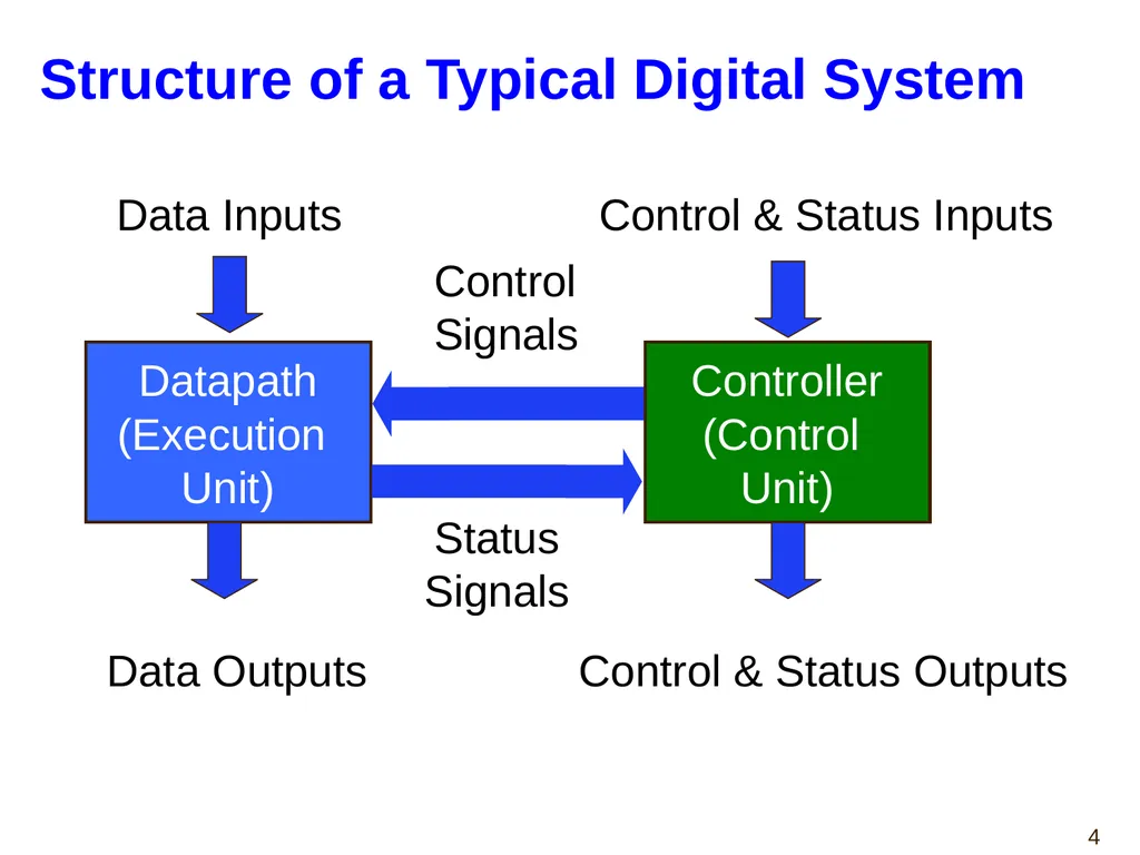
Structure of a Typical Digital System Datapath
(Execution
Unit) Controller
(Control
Unit) Data Inputs Data Outputs Control & Status Inputs Control & Status Outputs Control
Signals Status
Signals<br>
(Execution
Unit) Controller
(Control
Unit) Data Inputs Data Outputs Control & Status Inputs Control & Status Outputs Control
Signals Status
Signals<br>
05
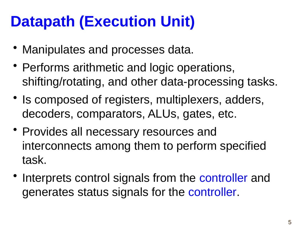
Datapath (Execution Unit) Manipulates and processes data.
Performs arithmetic and logic operations, shifting/rotating, and other data-processing tasks.
Is composed of registers, multiplexers, adders, decoders, comparators, ALUs, gates, etc.
Provides all necessary resources and interconnects among them to perform specified task.
Interprets control signals from the controller and generates status signals for the controller.<br>
Performs arithmetic and logic operations, shifting/rotating, and other data-processing tasks.
Is composed of registers, multiplexers, adders, decoders, comparators, ALUs, gates, etc.
Provides all necessary resources and interconnects among them to perform specified task.
Interprets control signals from the controller and generates status signals for the controller.<br>
06
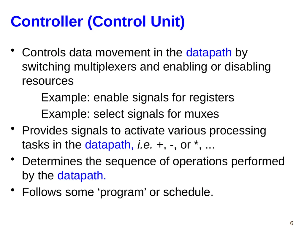
Controller (Control Unit) Controls data movement in the datapath by switching multiplexers and enabling or disabling resources
Example: enable signals for registers
Example: select signals for muxes
Provides signals to activate various processing tasks in the datapath, i.e. +, -, or *, ...
Determines the sequence of operations performed by the datapath.
Follows some ‘program’ or schedule.<br>
Example: enable signals for registers
Example: select signals for muxes
Provides signals to activate various processing tasks in the datapath, i.e. +, -, or *, ...
Determines the sequence of operations performed by the datapath.
Follows some ‘program’ or schedule.<br>
07
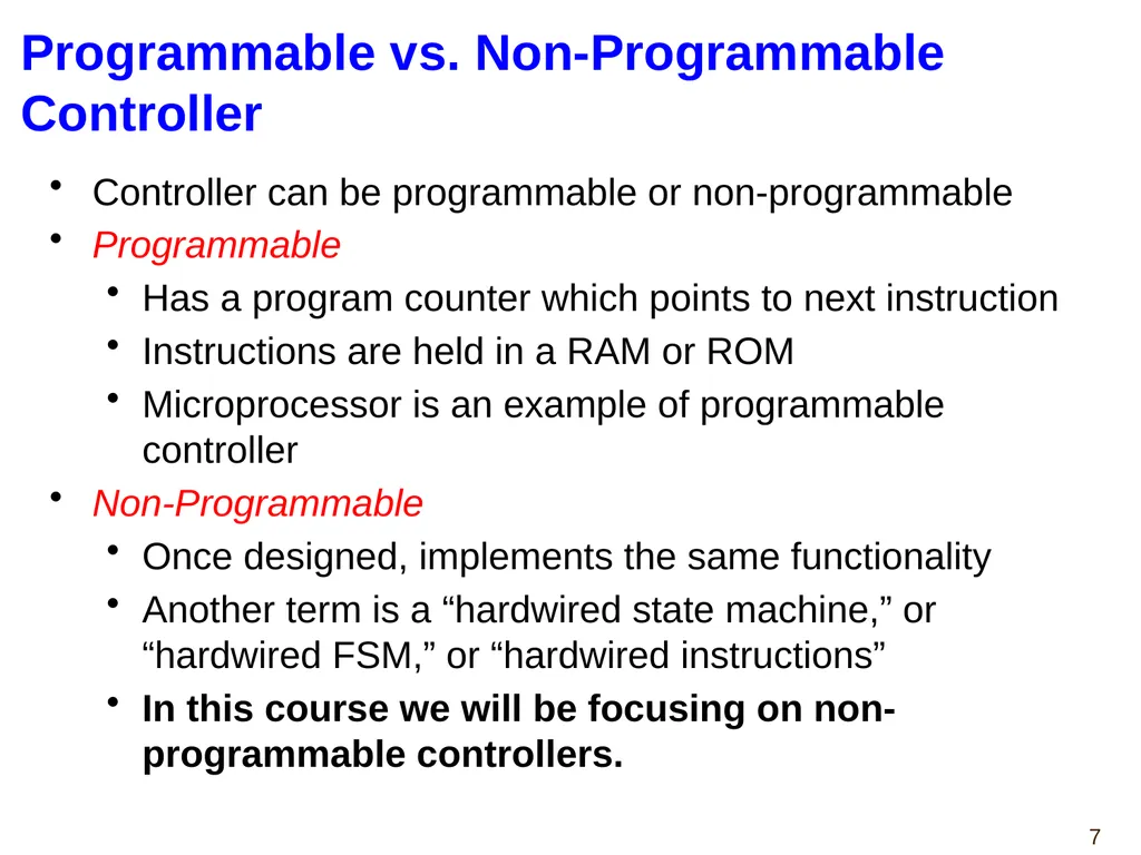
Programmable vs. Non-Programmable Controller Controller can be programmable or non-programmable
Programmable
Has a program counter which points to next instruction
Instructions are held in a RAM or ROM
Microprocessor is an example of programmable controller
Non-Programmable
Once designed, implements the same functionality
Another term is a “hardwired state machine,” or “hardwired FSM,” or “hardwired instructions”
In this course we will be focusing on non-programmable controllers.<br>
Programmable
Has a program counter which points to next instruction
Instructions are held in a RAM or ROM
Microprocessor is an example of programmable controller
Non-Programmable
Once designed, implements the same functionality
Another term is a “hardwired state machine,” or “hardwired FSM,” or “hardwired instructions”
In this course we will be focusing on non-programmable controllers.<br>
08
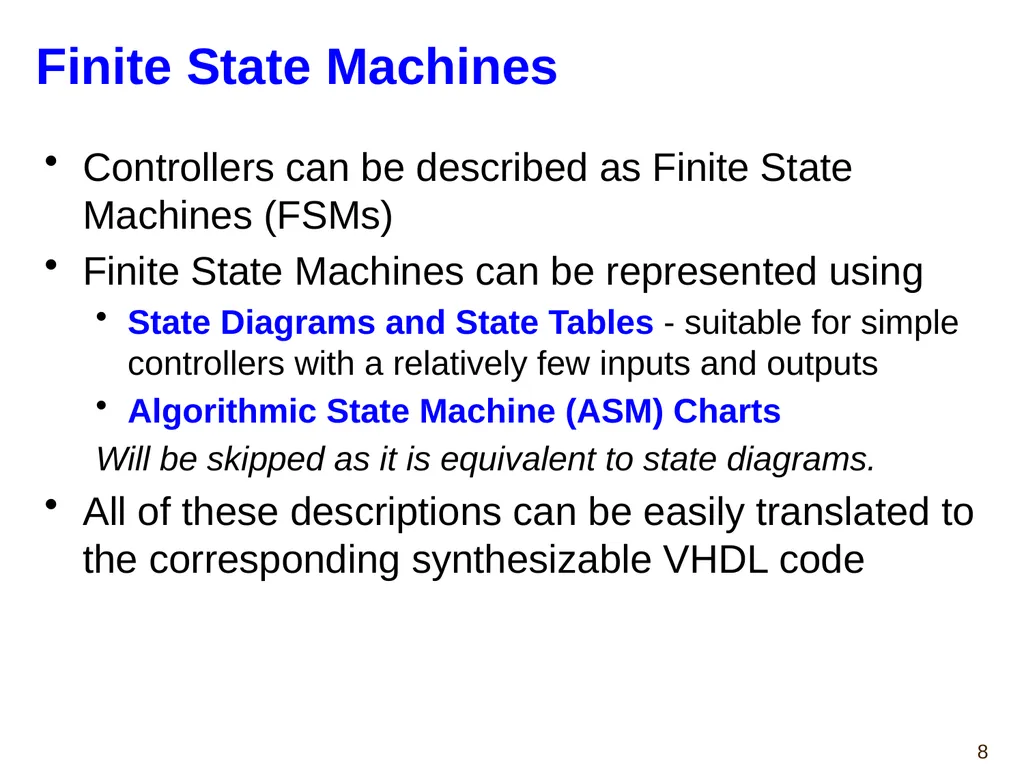
Finite State Machines Controllers can be described as Finite State Machines (FSMs)
Finite State Machines can be represented using
State Diagrams and State Tables - suitable for simple controllers with a relatively few inputs and outputs
Algorithmic State Machine (ASM) Charts
Will be skipped as it is equivalent to state diagrams.
All of these descriptions can be easily translated to the corresponding synthesizable VHDL code<br>
Finite State Machines can be represented using
State Diagrams and State Tables - suitable for simple controllers with a relatively few inputs and outputs
Algorithmic State Machine (ASM) Charts
Will be skipped as it is equivalent to state diagrams.
All of these descriptions can be easily translated to the corresponding synthesizable VHDL code<br>
09
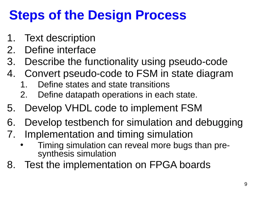
Steps of the Design Process 9 Text description
Define interface
Describe the functionality using pseudo-code
Convert pseudo-code to FSM in state diagram
Define states and state transitions
Define datapath operations in each state.
Develop VHDL code to implement FSM
Develop testbench for simulation and debugging
Implementation and timing simulation
Timing simulation can reveal more bugs than pre-synthesis simulation
Test the implementation on FPGA boards<br>
Define interface
Describe the functionality using pseudo-code
Convert pseudo-code to FSM in state diagram
Define states and state transitions
Define datapath operations in each state.
Develop VHDL code to implement FSM
Develop testbench for simulation and debugging
Implementation and timing simulation
Timing simulation can reveal more bugs than pre-synthesis simulation
Test the implementation on FPGA boards<br>
10
Finite State Machines
Refresher<br>
Refresher<br>
11
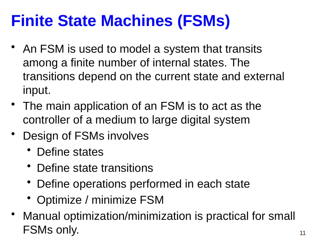
Finite State Machines (FSMs) An FSM is used to model a system that transits among a finite number of internal states. The transitions depend on the current state and external input.
The main application of an FSM is to act as the controller of a medium to large digital system
Design of FSMs involves
Define states
Define state transitions
Define operations performed in each state
Optimize / minimize FSM
Manual optimization/minimization is practical for small FSMs only.<br>
The main application of an FSM is to act as the controller of a medium to large digital system
Design of FSMs involves
Define states
Define state transitions
Define operations performed in each state
Optimize / minimize FSM
Manual optimization/minimization is practical for small FSMs only.<br>
12
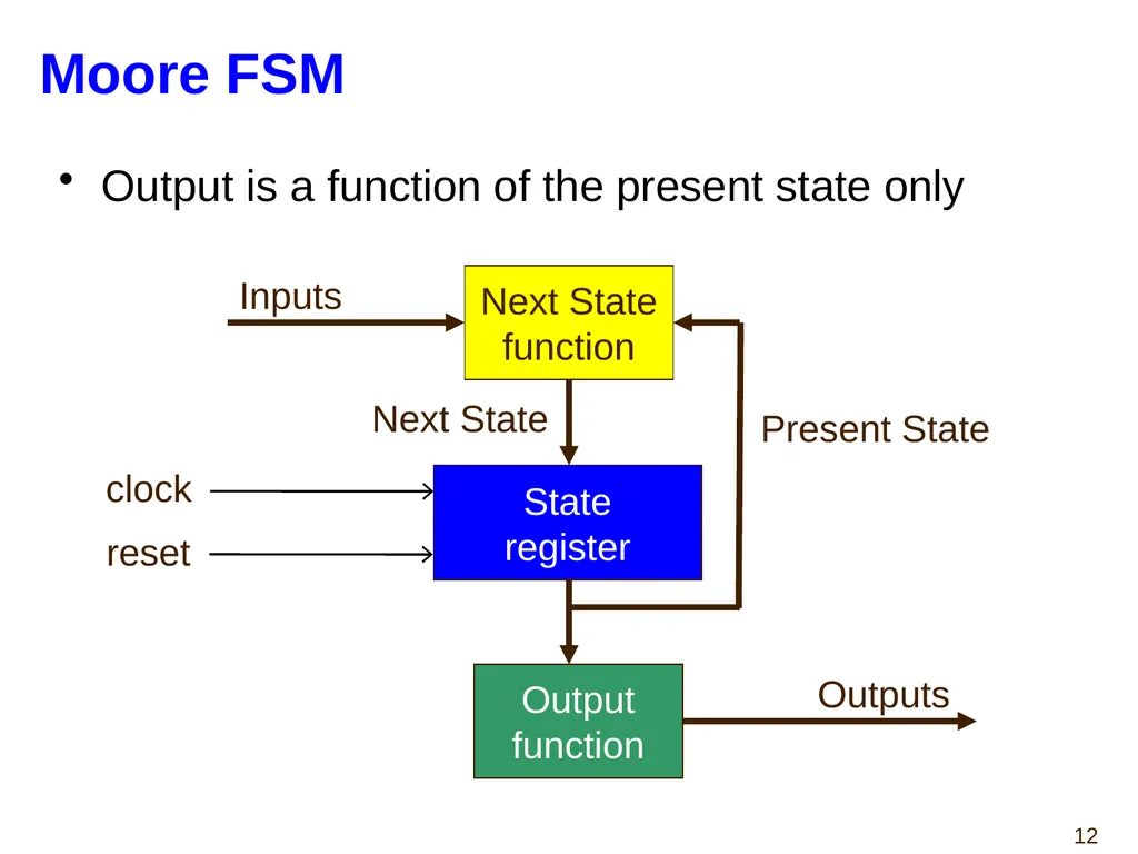
Moore FSM Output is a function of the present state only State
register Next State
function Output
function Inputs Present State Next State Outputs clock reset<br>
function Output
function Inputs Present State Next State Outputs clock reset<br>
13
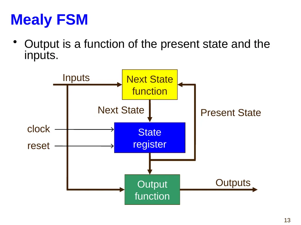
Mealy FSM Output is a function of the present state and the inputs. Next State
function Output
function Inputs Present State Next State Outputs State register clock reset<br>
function Output
function Inputs Present State Next State Outputs State register clock reset<br>
14
State Diagrams<br>
15
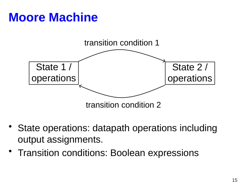
Moore Machine State operations: datapath operations including output assignments.
Transition conditions: Boolean expressions transition condition 1 transition condition 2 State 1 /
operations State 2 /
operations<br>
Transition conditions: Boolean expressions transition condition 1 transition condition 2 State 1 /
operations State 2 /
operations<br>
16
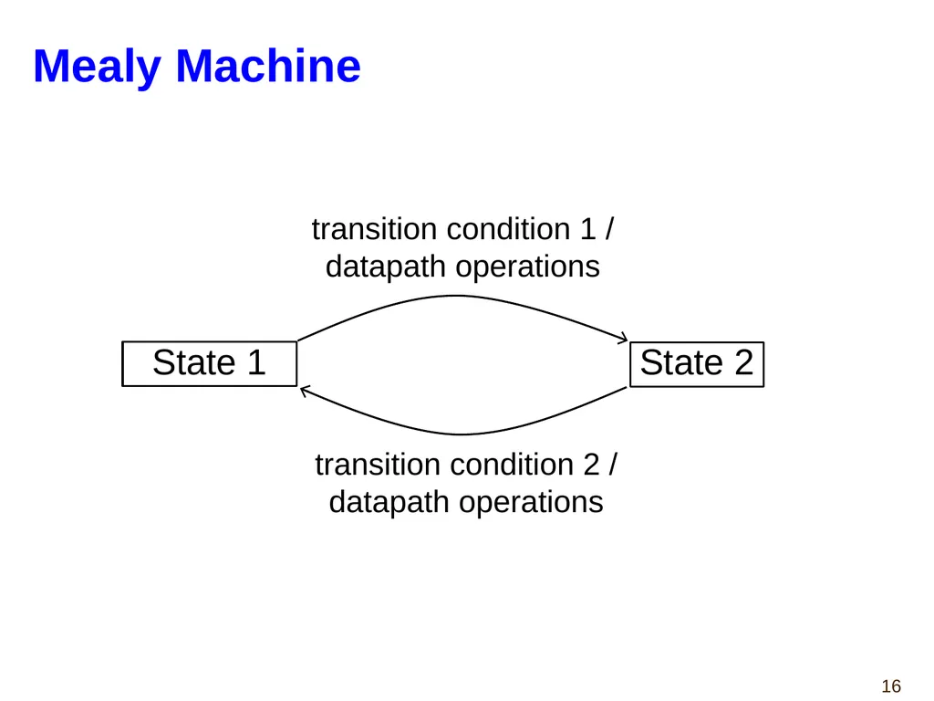
Mealy Machine transition condition 1 /
datapath operations transition condition 2 /
datapath operations State 1 State 2<br>
datapath operations transition condition 2 /
datapath operations State 1 State 2<br>
17
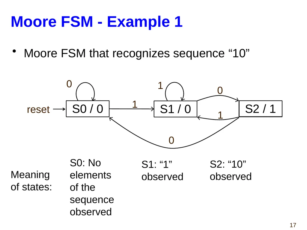
Moore FSM - Example 1 Moore FSM that recognizes sequence “10” reset Meaning
of states: S0: No
elements
of the
sequence
observed S1: “1”
observed S2: “10”
observed S0 / 0 S1 / 0 S2 / 1 1 0 1 0 0 1<br>
of states: S0: No
elements
of the
sequence
observed S1: “1”
observed S2: “10”
observed S0 / 0 S1 / 0 S2 / 1 1 0 1 0 0 1<br>
18
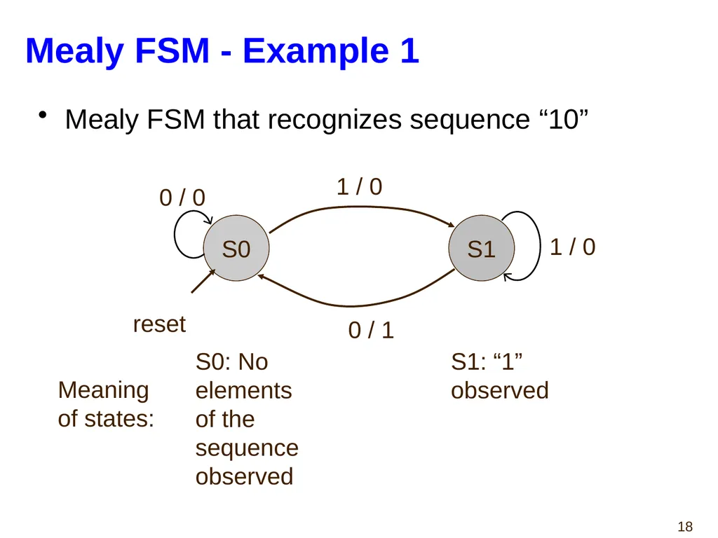
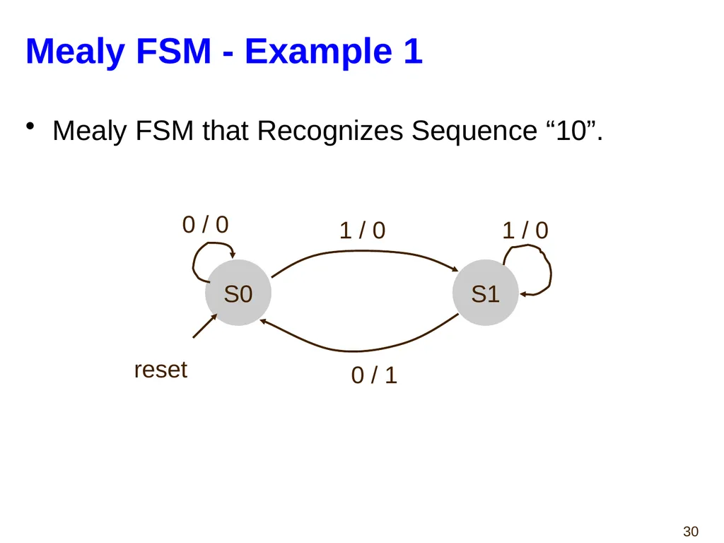
Mealy FSM - Example 1 Mealy FSM that recognizes sequence “10” S0 S1 0 / 0 1 / 0 1 / 0 0 / 1 reset Meaning
of states: S0: No
elements
of the
sequence
observed S1: “1”
observed<br>
of states: S0: No
elements
of the
sequence
observed S1: “1”
observed<br>
19
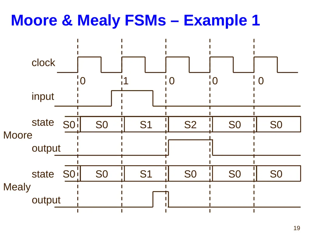
Moore & Mealy FSMs – Example 1 clock input Moore Mealy 0 1 0 0 0 S0 S0 S1 S2 S0 S0 S0 S0 S1 S0 S0 S0 state output state output<br>
20
Moore vs. Mealy FSM (1) Moore and Mealy FSMs are functionally equivalent.
Equivalent Mealy FSM can be derived from Moore FSM and vice versa.
Mealy FSM has richer description and usually requires less number of states
Smaller circuit area.<br>
Equivalent Mealy FSM can be derived from Moore FSM and vice versa.
Mealy FSM has richer description and usually requires less number of states
Smaller circuit area.<br>
21
Moore vs. Mealy FSM (2) Mealy FSM computes outputs as soon as inputs change.
Mealy FSM responds one clock cycle sooner than equivalent Moore FSM.
There are direct paths from inputs to outputs – can cause output glitches.
Moore FSM has no combinational path between inputs and outputs.
Less likely to affect the critical path of the entire circuit.<br>
Mealy FSM responds one clock cycle sooner than equivalent Moore FSM.
There are direct paths from inputs to outputs – can cause output glitches.
Moore FSM has no combinational path between inputs and outputs.
Less likely to affect the critical path of the entire circuit.<br>
22
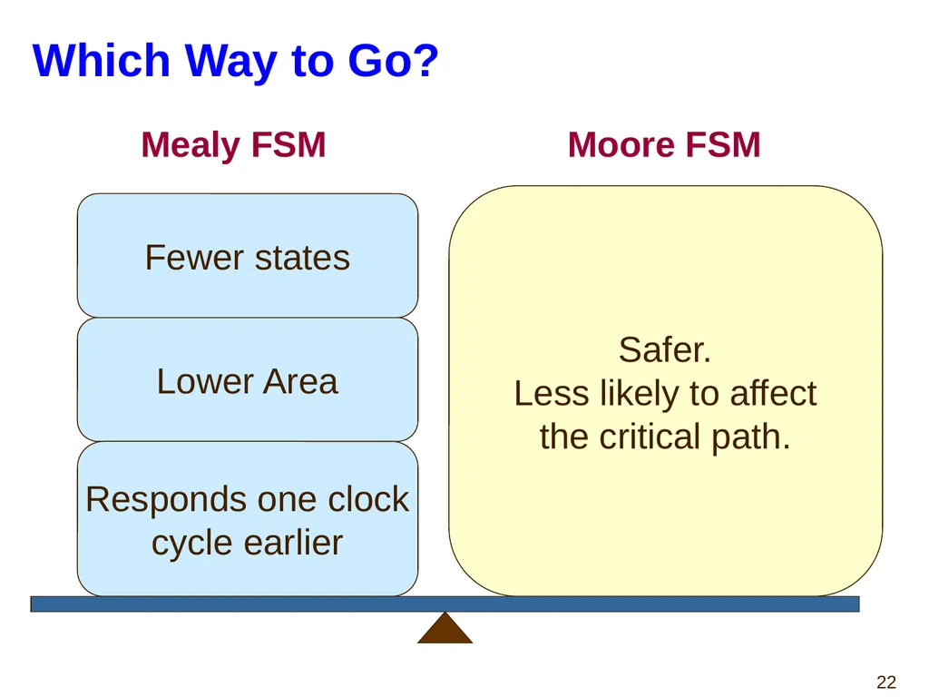
Which Way to Go? Safer.
Less likely to affect
the critical path. Mealy FSM Moore FSM Lower Area Responds one clock
cycle earlier Fewer states<br>
Less likely to affect
the critical path. Mealy FSM Moore FSM Lower Area Responds one clock
cycle earlier Fewer states<br>
23
Finite State Machines
in VHDL<br>
in VHDL<br>
24
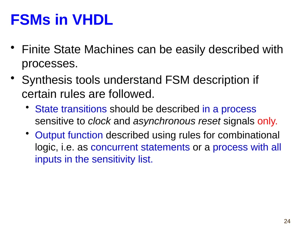
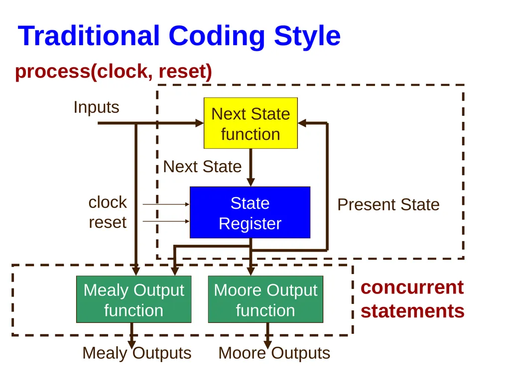
FSMs in VHDL Finite State Machines can be easily described with processes.
Synthesis tools understand FSM description if certain rules are followed.
State transitions should be described in a process sensitive to clock and asynchronous reset signals only.
Output function described using rules for combinational logic, i.e. as concurrent statements or a process with all inputs in the sensitivity list.<br>
Synthesis tools understand FSM description if certain rules are followed.
State transitions should be described in a process sensitive to clock and asynchronous reset signals only.
Output function described using rules for combinational logic, i.e. as concurrent statements or a process with all inputs in the sensitivity list.<br>
25
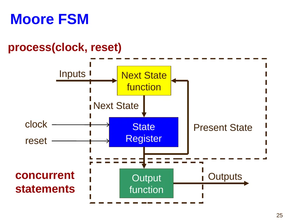
Moore FSM State
Register Next State
function Output
function Inputs Present State Next State Outputs process(clock, reset) concurrent
statements clock reset<br>
function Output
function Inputs Present State Next State Outputs process(clock, reset) concurrent
statements clock reset<br>
26
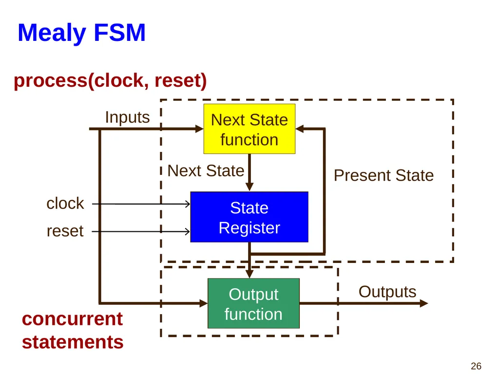
Mealy FSM Next State
function Output
function Inputs Present State Next State Outputs State Register process(clock, reset) concurrent
statements clock reset<br>
function Output
function Inputs Present State Next State Outputs State Register process(clock, reset) concurrent
statements clock reset<br>
27
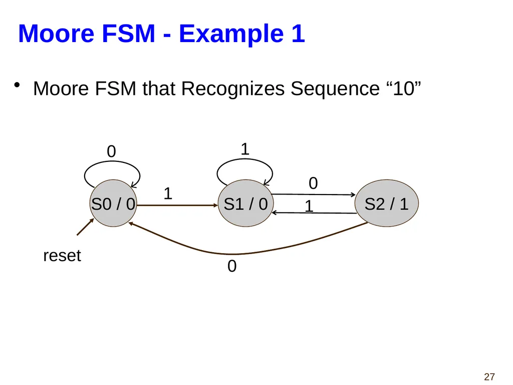
Moore FSM - Example 1 Moore FSM that Recognizes Sequence “10” S0 / 0 S1 / 0 S2 / 1 0 0 0 1 1 1 reset<br>
28
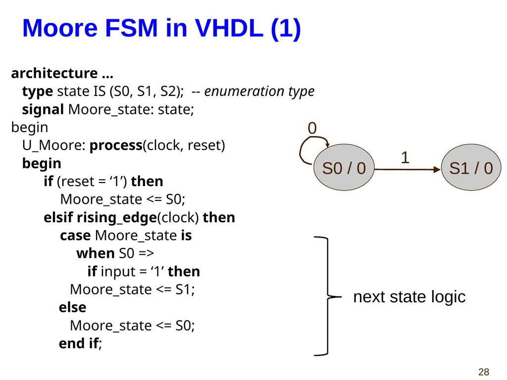
Moore FSM in VHDL (1) architecture ...
type state IS (S0, S1, S2); -- enumeration type
signal Moore_state: state;
begin
U_Moore: process(clock, reset)
begin
if (reset = ‘1’) then
Moore_state <= S0;
elsif rising_edge(clock) then
case Moore_state is
when S0 =>
if input = ‘1’ then
Moore_state <= S1;
else
Moore_state <= S0;
end if; S0 / 0 S1 / 0 0 1 next state logic<br>
type state IS (S0, S1, S2); -- enumeration type
signal Moore_state: state;
begin
U_Moore: process(clock, reset)
begin
if (reset = ‘1’) then
Moore_state <= S0;
elsif rising_edge(clock) then
case Moore_state is
when S0 =>
if input = ‘1’ then
Moore_state <= S1;
else
Moore_state <= S0;
end if; S0 / 0 S1 / 0 0 1 next state logic<br>
29
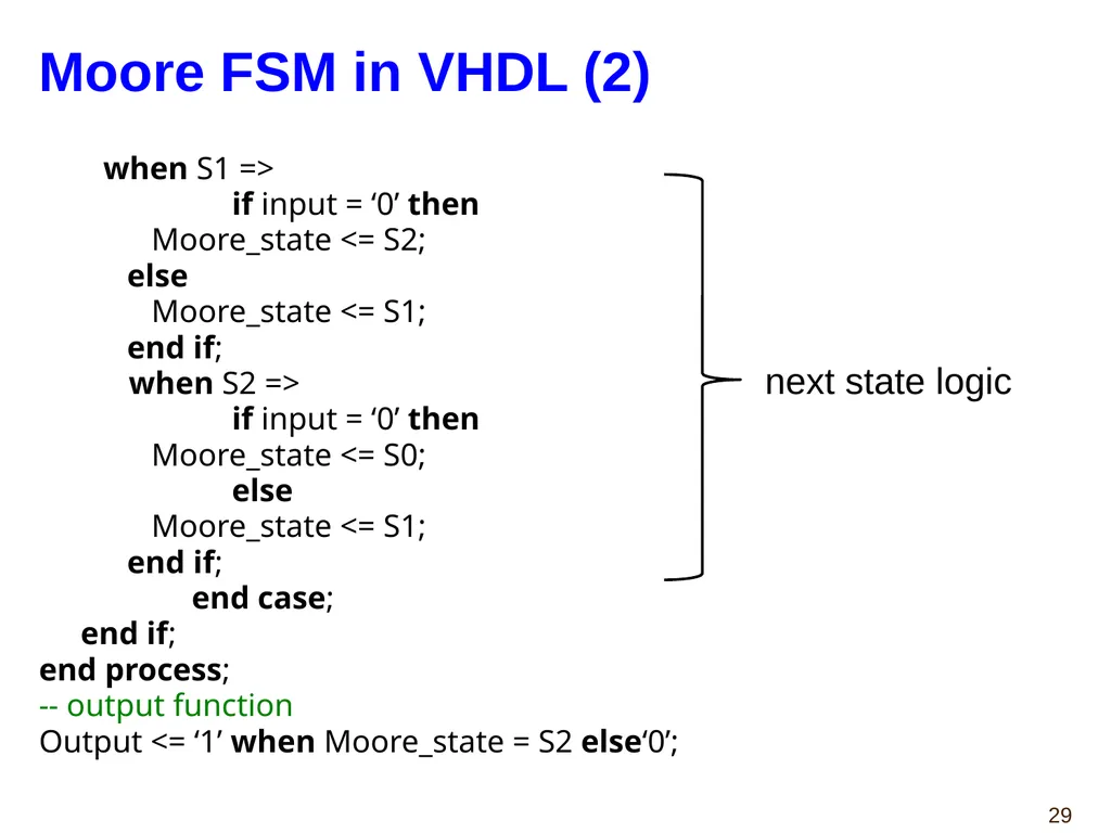
Moore FSM in VHDL (2) when S1 =>
if input = ‘0’ then
Moore_state <= S2;
else
Moore_state <= S1;
end if;
when S2 =>
if input = ‘0’ then
Moore_state <= S0;
else
Moore_state <= S1;
end if;
end case;
end if;
end process;
-- output function
Output <= ‘1’ when Moore_state = S2 else‘0’; next state logic<br>
if input = ‘0’ then
Moore_state <= S2;
else
Moore_state <= S1;
end if;
when S2 =>
if input = ‘0’ then
Moore_state <= S0;
else
Moore_state <= S1;
end if;
end case;
end if;
end process;
-- output function
Output <= ‘1’ when Moore_state = S2 else‘0’; next state logic<br>
30
Mealy FSM - Example 1 Mealy FSM that Recognizes Sequence “10”.<br>
31
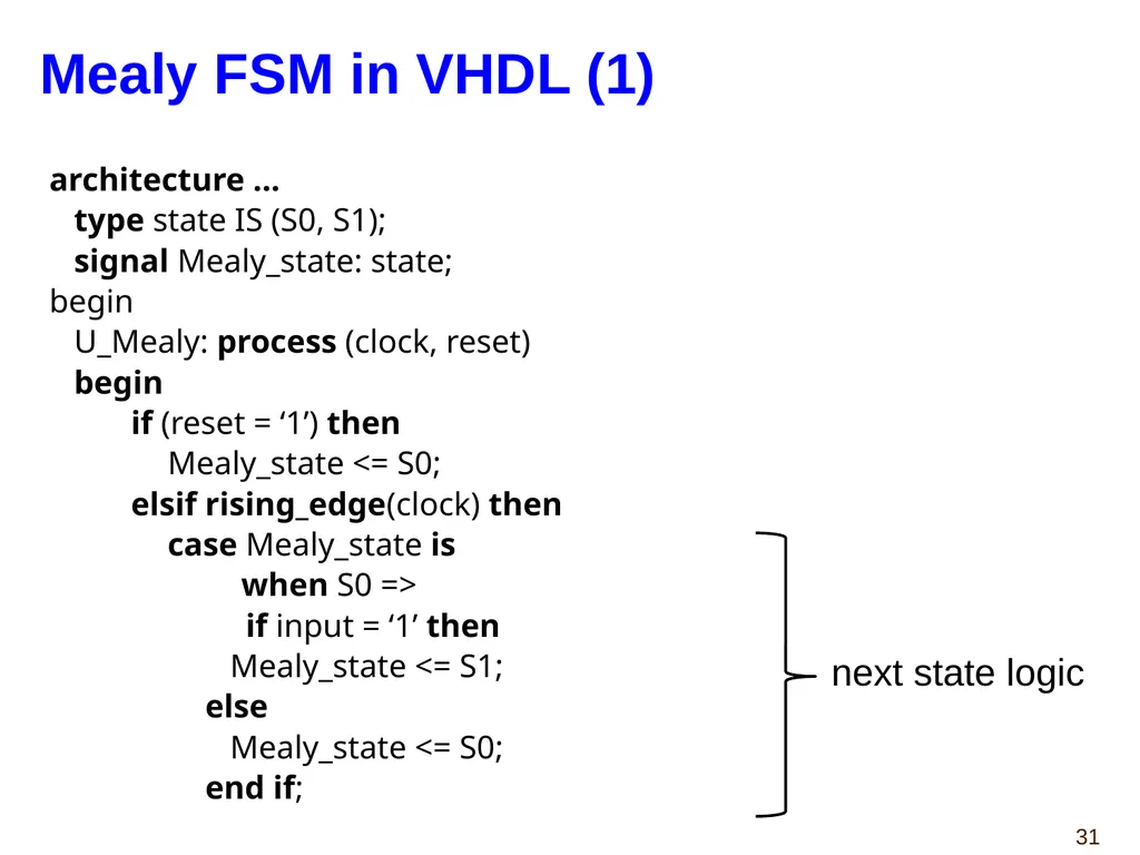
Mealy FSM in VHDL (1) architecture ...
type state IS (S0, S1);
signal Mealy_state: state;
begin
U_Mealy: process (clock, reset)
begin
if (reset = ‘1’) then
Mealy_state <= S0;
elsif rising_edge(clock) then
case Mealy_state is
when S0 =>
if input = ‘1’ then
Mealy_state <= S1;
else
Mealy_state <= S0;
end if; next state logic<br>
type state IS (S0, S1);
signal Mealy_state: state;
begin
U_Mealy: process (clock, reset)
begin
if (reset = ‘1’) then
Mealy_state <= S0;
elsif rising_edge(clock) then
case Mealy_state is
when S0 =>
if input = ‘1’ then
Mealy_state <= S1;
else
Mealy_state <= S0;
end if; next state logic<br>
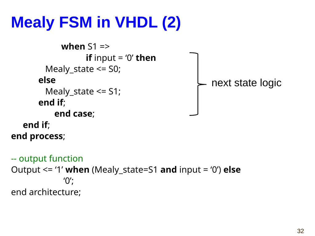
32
Mealy FSM in VHDL (2) when S1 =>
if input = ‘0’ then
Mealy_state <= S0;
else
Mealy_state <= S1;
end if;
end case;
end if;
end process;
-- output function
Output <= ‘1’ when (Mealy_state=S1 and input = ‘0’) else
‘0’;
end architecture; next state logic<br>
if input = ‘0’ then
Mealy_state <= S0;
else
Mealy_state <= S1;
end if;
end case;
end if;
end process;
-- output function
Output <= ‘1’ when (Mealy_state=S1 and input = ‘0’) else
‘0’;
end architecture; next state logic<br>
33
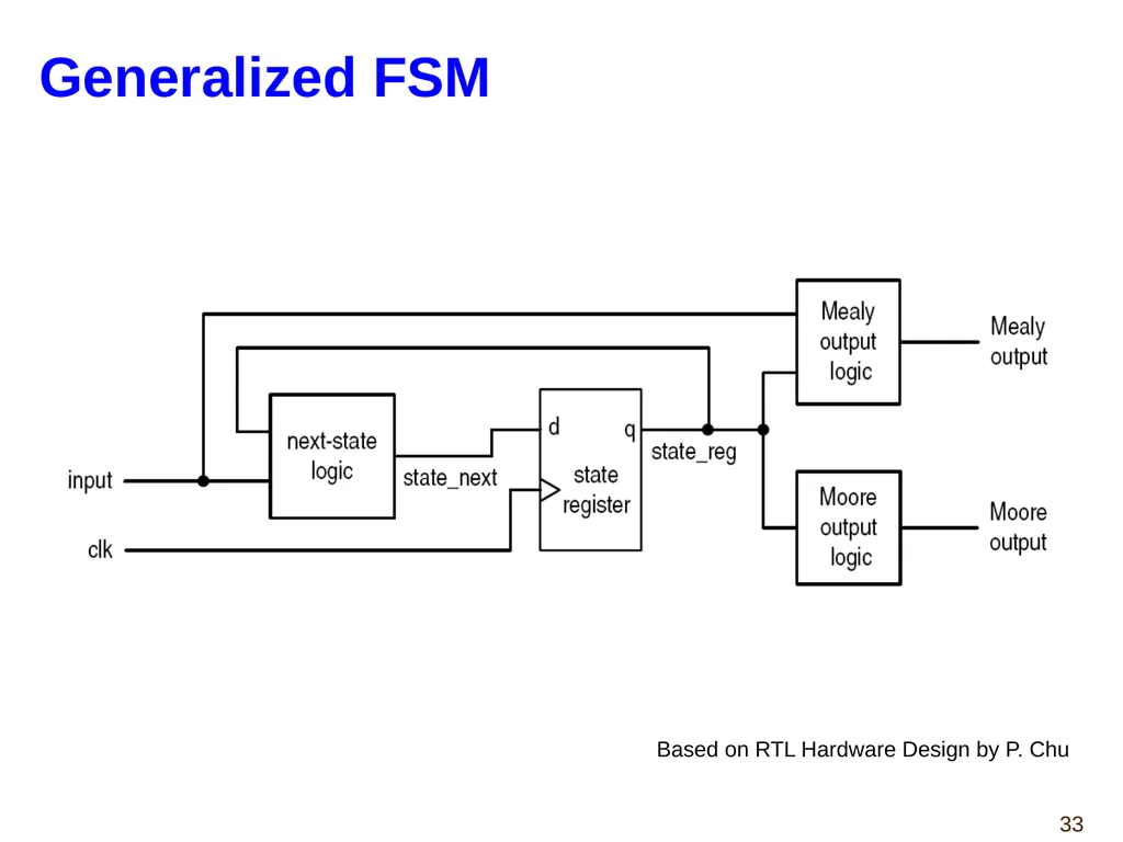
Generalized FSM Based on RTL Hardware Design by P. Chu<br>
34
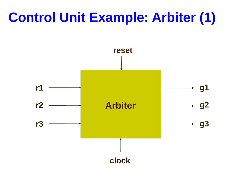
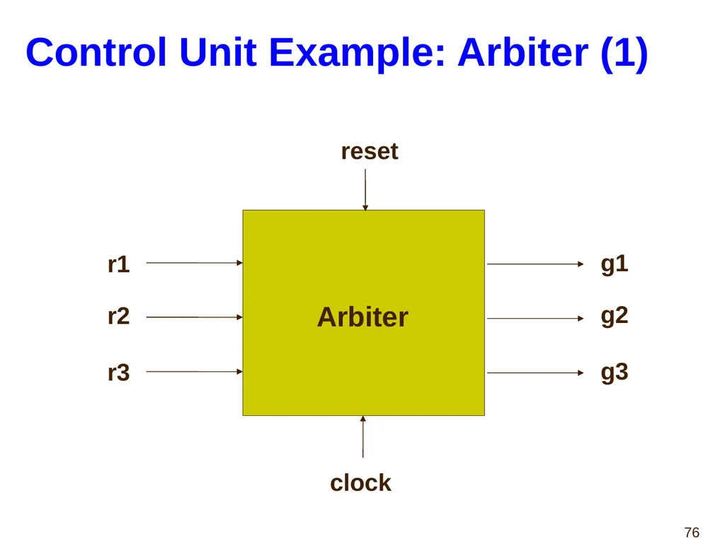
Control Unit Example: Arbiter (1) Arbiter reset r1 r2 r3 g1 g2 g3 clock<br>
35
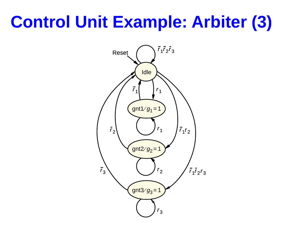
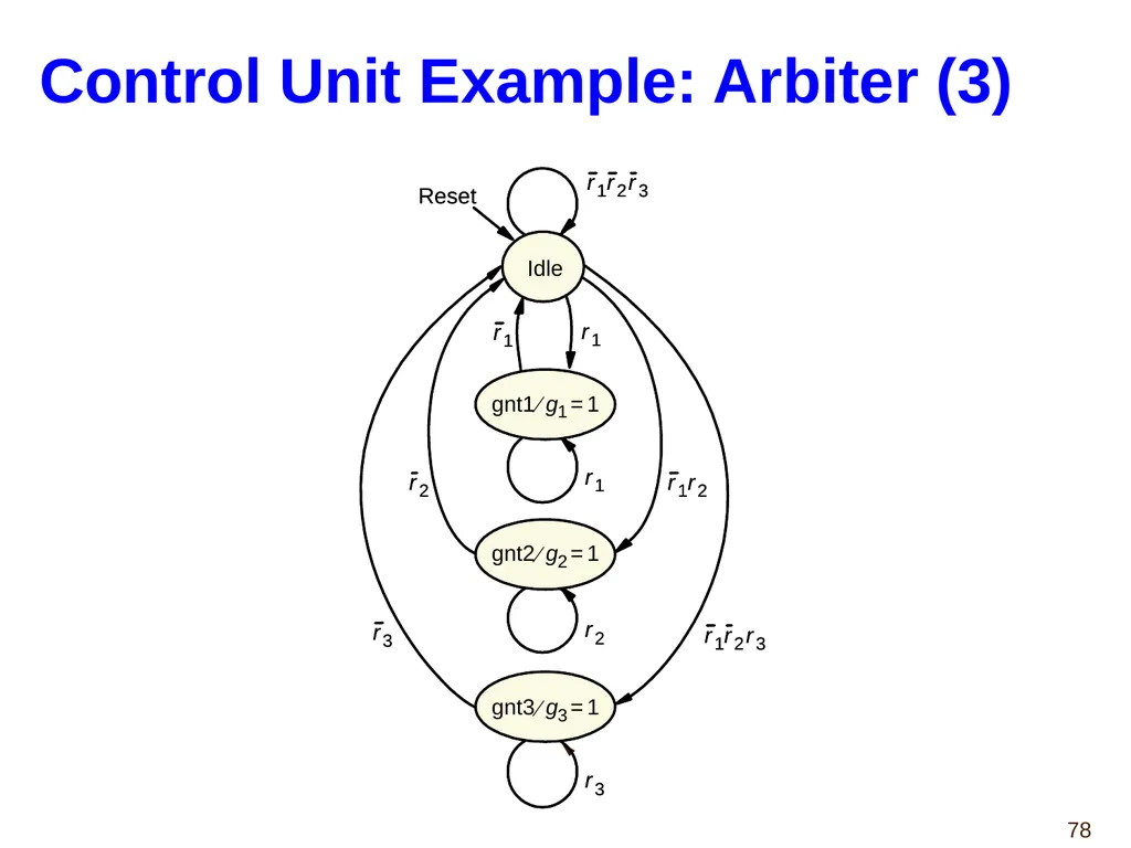
Control Unit Example: Arbiter (3)<br>
36
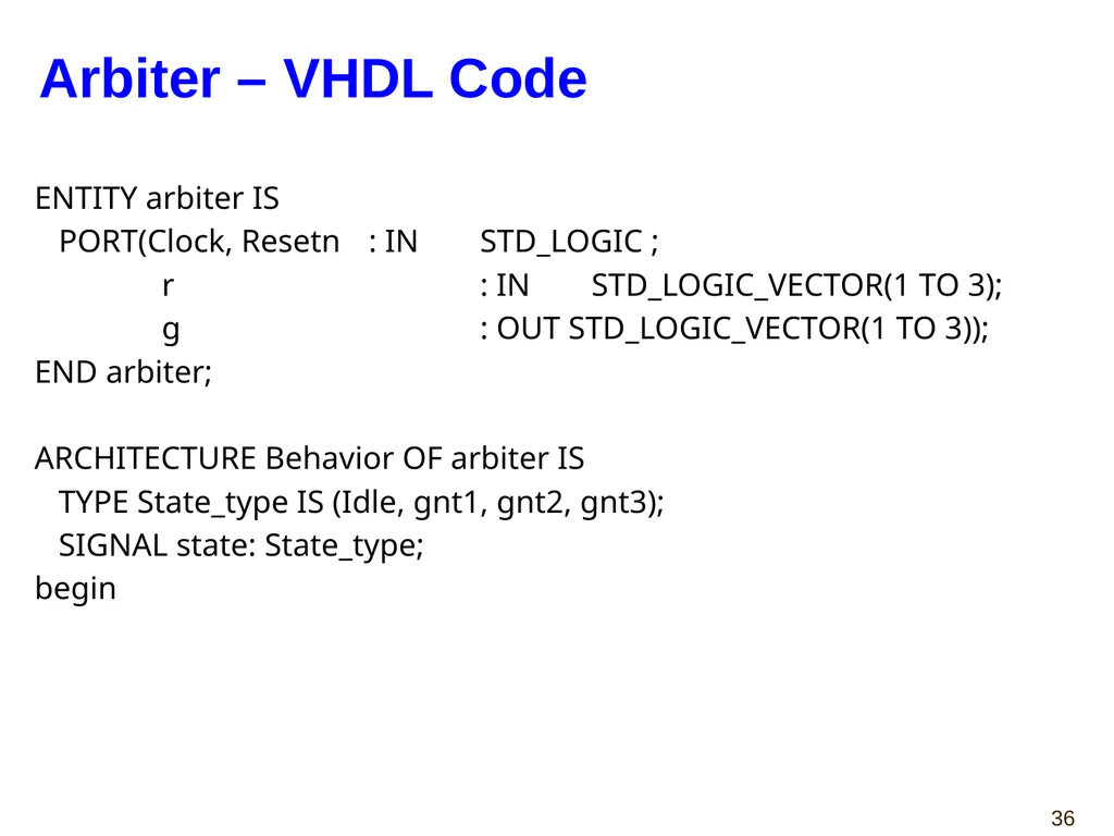
ENTITY arbiter IS
PORT(Clock, Resetn : IN STD_LOGIC ;
r : IN STD_LOGIC_VECTOR(1 TO 3);
g : OUT STD_LOGIC_VECTOR(1 TO 3));
END arbiter;
ARCHITECTURE Behavior OF arbiter IS
TYPE State_type IS (Idle, gnt1, gnt2, gnt3);
SIGNAL state: State_type;
begin Arbiter – VHDL Code<br>
PORT(Clock, Resetn : IN STD_LOGIC ;
r : IN STD_LOGIC_VECTOR(1 TO 3);
g : OUT STD_LOGIC_VECTOR(1 TO 3));
END arbiter;
ARCHITECTURE Behavior OF arbiter IS
TYPE State_type IS (Idle, gnt1, gnt2, gnt3);
SIGNAL state: State_type;
begin Arbiter – VHDL Code<br>
37
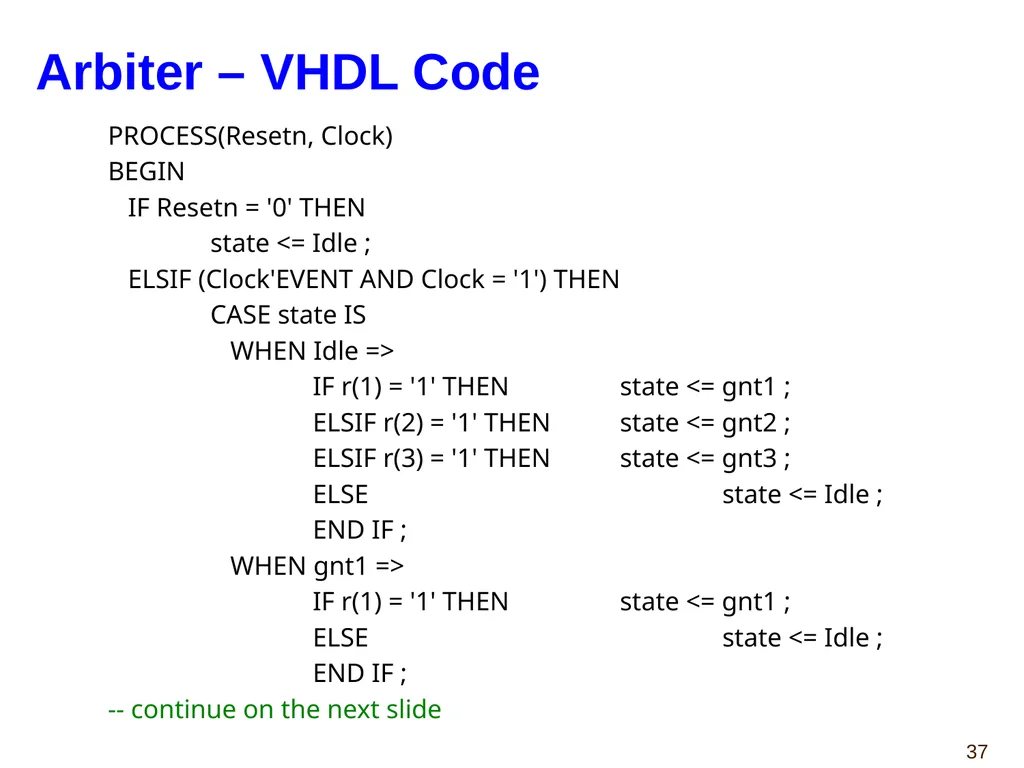
PROCESS(Resetn, Clock)
BEGIN
IF Resetn = '0' THEN
state <= Idle ;
ELSIF (Clock'EVENT AND Clock = '1') THEN
CASE state IS
WHEN Idle =>
IF r(1) = '1' THEN state <= gnt1 ;
ELSIF r(2) = '1' THEN state <= gnt2 ;
ELSIF r(3) = '1' THEN state <= gnt3 ;
ELSE state <= Idle ;
END IF ;
WHEN gnt1 =>
IF r(1) = '1' THEN state <= gnt1 ;
ELSE state <= Idle ;
END IF ;
-- continue on the next slide Arbiter – VHDL Code<br>
BEGIN
IF Resetn = '0' THEN
state <= Idle ;
ELSIF (Clock'EVENT AND Clock = '1') THEN
CASE state IS
WHEN Idle =>
IF r(1) = '1' THEN state <= gnt1 ;
ELSIF r(2) = '1' THEN state <= gnt2 ;
ELSIF r(3) = '1' THEN state <= gnt3 ;
ELSE state <= Idle ;
END IF ;
WHEN gnt1 =>
IF r(1) = '1' THEN state <= gnt1 ;
ELSE state <= Idle ;
END IF ;
-- continue on the next slide Arbiter – VHDL Code<br>
38
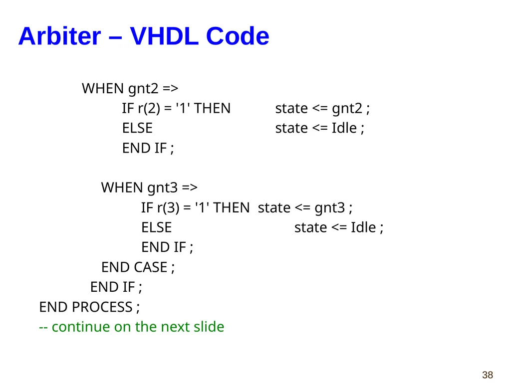
WHEN gnt2 =>
IF r(2) = '1' THEN state <= gnt2 ;
ELSE state <= Idle ;
END IF ;
WHEN gnt3 =>
IF r(3) = '1' THEN state <= gnt3 ;
ELSE state <= Idle ;
END IF ;
END CASE ;
END IF ;
END PROCESS ;
-- continue on the next slide Arbiter – VHDL Code<br>
IF r(2) = '1' THEN state <= gnt2 ;
ELSE state <= Idle ;
END IF ;
WHEN gnt3 =>
IF r(3) = '1' THEN state <= gnt3 ;
ELSE state <= Idle ;
END IF ;
END CASE ;
END IF ;
END PROCESS ;
-- continue on the next slide Arbiter – VHDL Code<br>
39
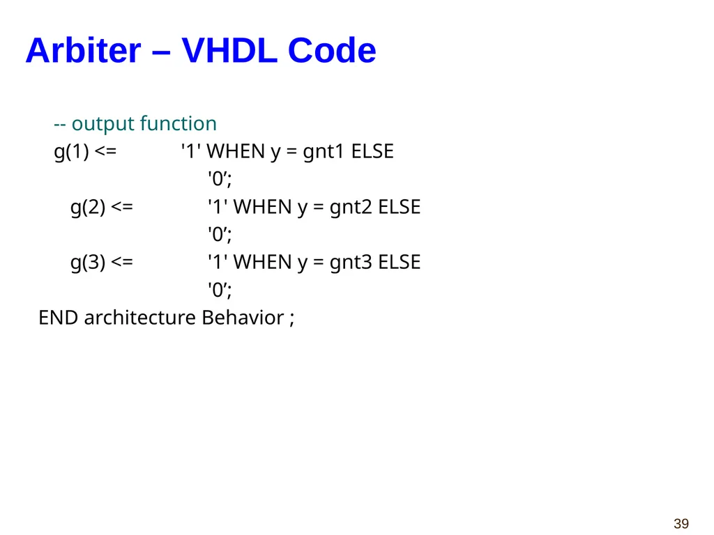
-- output function
g(1) <= '1' WHEN y = gnt1 ELSE
'0’;
g(2) <= '1' WHEN y = gnt2 ELSE
'0’;
g(3) <= '1' WHEN y = gnt3 ELSE
'0’;
END architecture Behavior ; Arbiter – VHDL Code<br>
g(1) <= '1' WHEN y = gnt1 ELSE
'0’;
g(2) <= '1' WHEN y = gnt2 ELSE
'0’;
g(3) <= '1' WHEN y = gnt3 ELSE
'0’;
END architecture Behavior ; Arbiter – VHDL Code<br>
40
Case Study 1
Debouncing Circuit<br>
Debouncing Circuit<br>
41
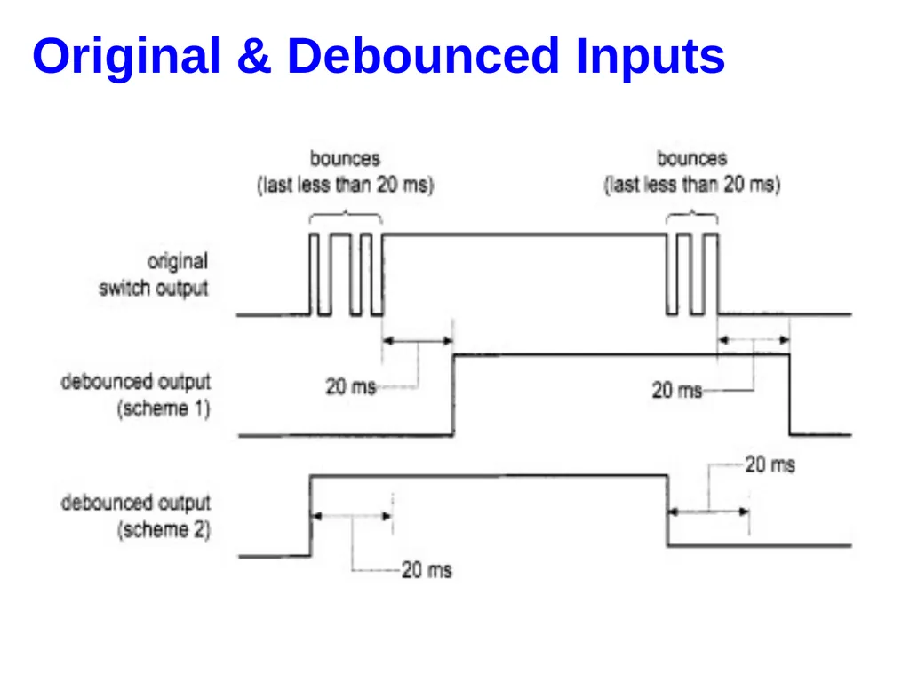
Original & Debounced Inputs<br>
42
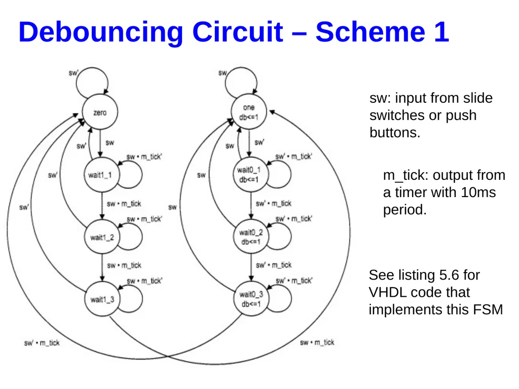
Debouncing Circuit – Scheme 1 sw: input from slide switches or push buttons. m_tick: output from a timer with 10ms period. See listing 5.6 for VHDL code that implements this FSM<br>
43
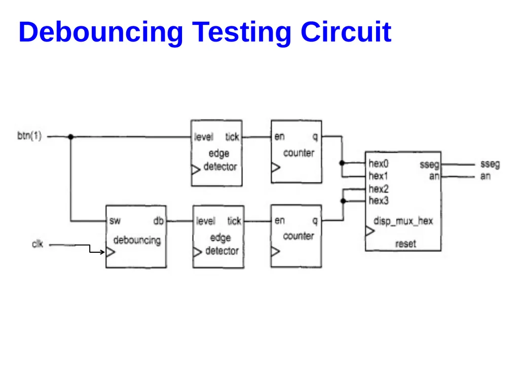
Debouncing Testing Circuit<br>
44
44 Case Study 2
Fibonacci Number<br>
Fibonacci Number<br>
45
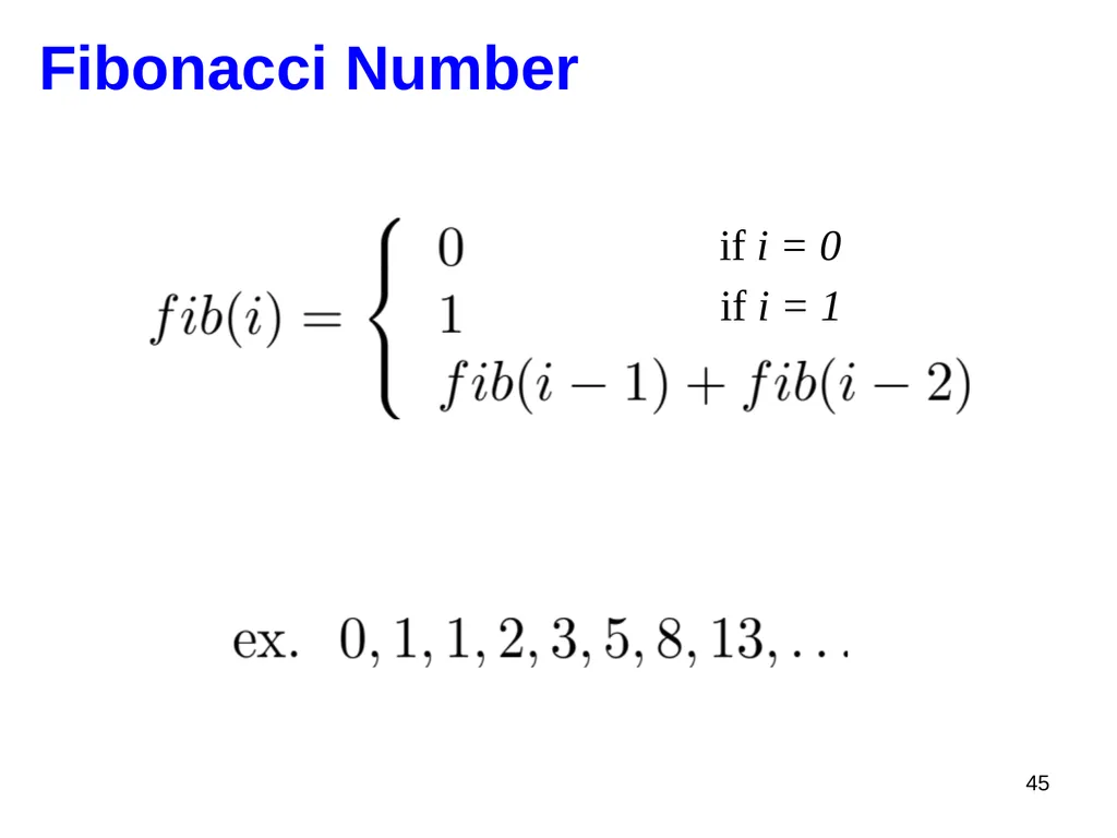
45 Fibonacci Number if i = 0 if i = 1<br>
46
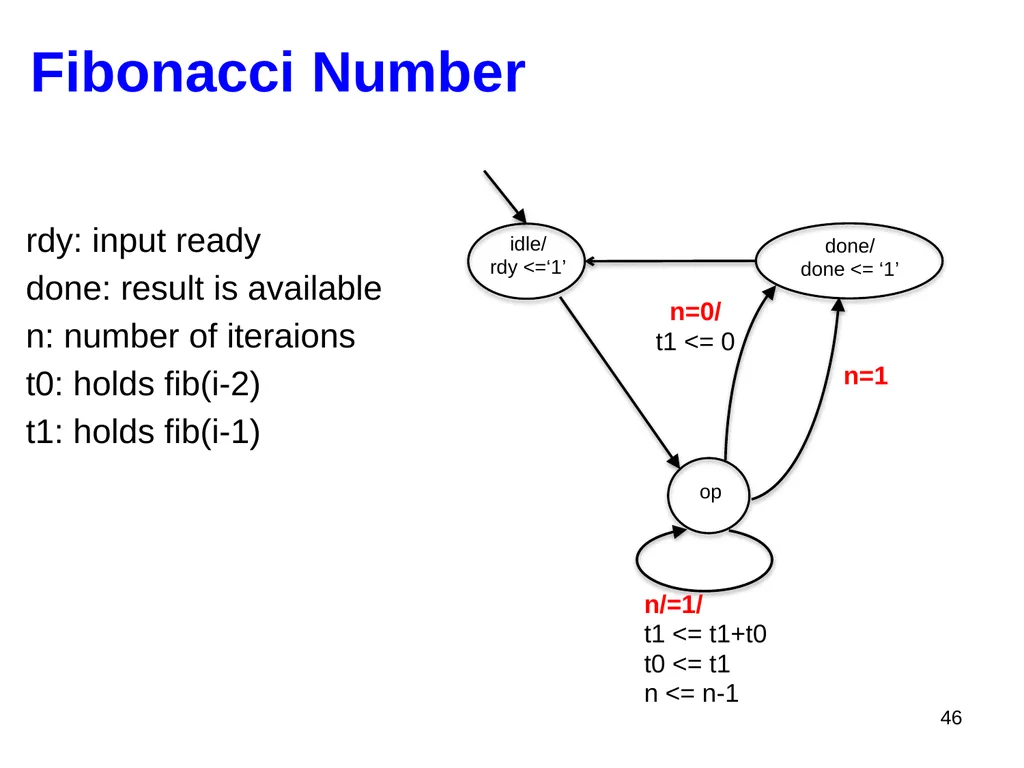
46 Fibonacci Number idle/
rdy <=‘1’ done/
done <= ‘1’ op n=0/
t1 <= 0 n/=1/
t1 <= t1+t0
t0 <= t1
n <= n-1 n=1 rdy: input ready
done: result is available
n: number of iteraions
t0: holds fib(i-2)
t1: holds fib(i-1)<br>
rdy <=‘1’ done/
done <= ‘1’ op n=0/
t1 <= 0 n/=1/
t1 <= t1+t0
t0 <= t1
n <= n-1 n=1 rdy: input ready
done: result is available
n: number of iteraions
t0: holds fib(i-2)
t1: holds fib(i-1)<br>
47
47 VHDL Variables<br>
48
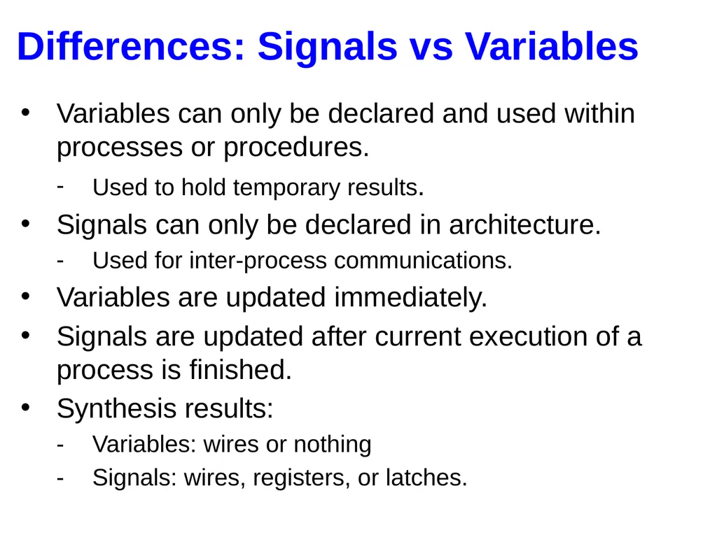
Differences: Signals vs Variables Variables can only be declared and used within processes or procedures.
Used to hold temporary results.
Signals can only be declared in architecture.
Used for inter-process communications.
Variables are updated immediately.
Signals are updated after current execution of a process is finished.
Synthesis results:
Variables: wires or nothing
Signals: wires, registers, or latches.<br>
Used to hold temporary results.
Signals can only be declared in architecture.
Used for inter-process communications.
Variables are updated immediately.
Signals are updated after current execution of a process is finished.
Synthesis results:
Variables: wires or nothing
Signals: wires, registers, or latches.<br>
49
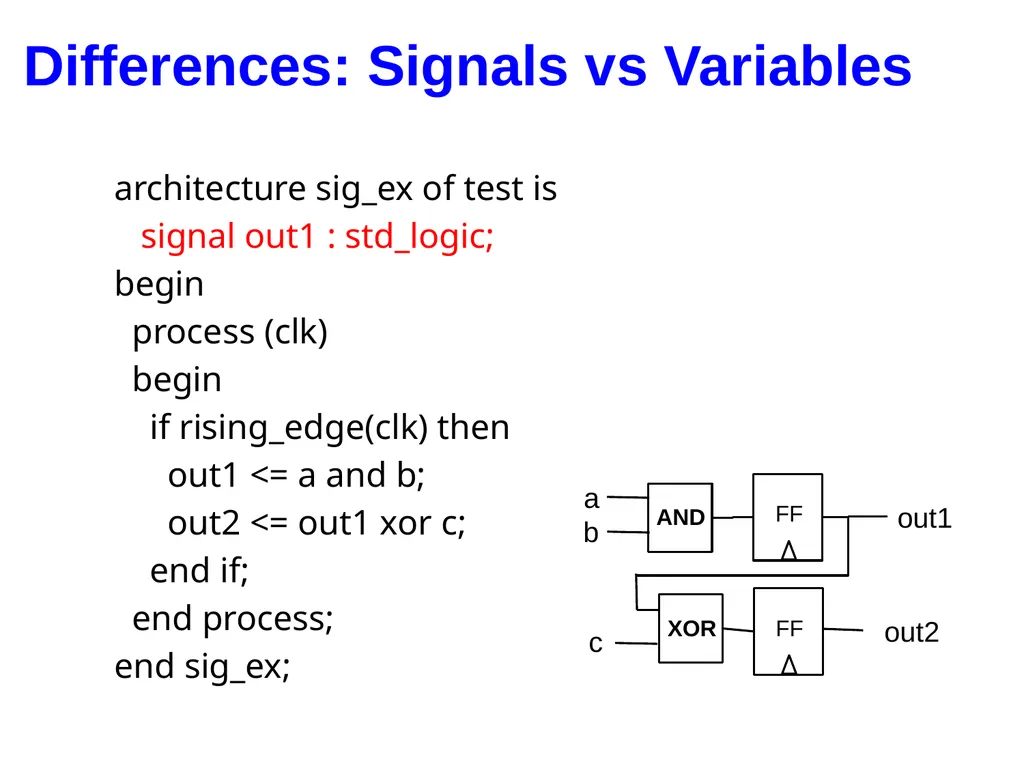
Differences: Signals vs Variables architecture sig_ex of test is
signal out1 : std_logic;
begin
process (clk)
begin
if rising_edge(clk) then
out1 <= a and b;
out2 <= out1 xor c;
end if;
end process;
end sig_ex; AND XOR a b c out1 out2<br>
signal out1 : std_logic;
begin
process (clk)
begin
if rising_edge(clk) then
out1 <= a and b;
out2 <= out1 xor c;
end if;
end process;
end sig_ex; AND XOR a b c out1 out2<br>
50
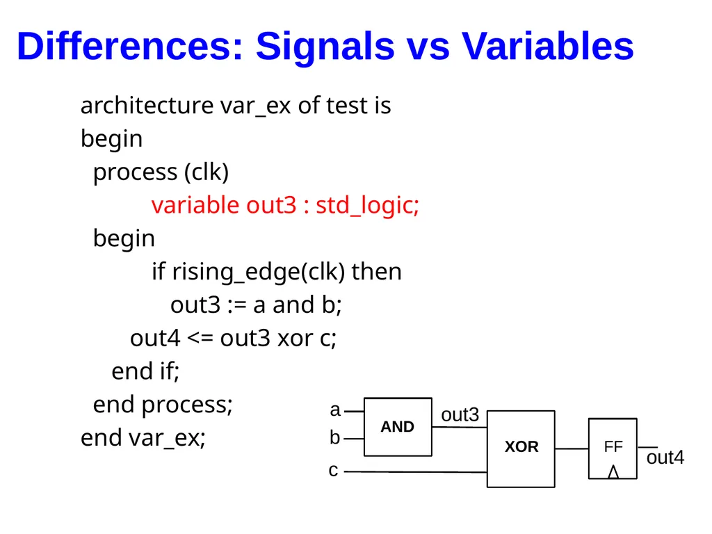
Differences: Signals vs Variables architecture var_ex of test is
begin
process (clk)
variable out3 : std_logic;
begin
if rising_edge(clk) then
out3 := a and b;
out4 <= out3 xor c;
end if;
end process;
end var_ex; AND XOR a b c out3 out4<br>
begin
process (clk)
variable out3 : std_logic;
begin
if rising_edge(clk) then
out3 := a and b;
out4 <= out3 xor c;
end if;
end process;
end var_ex; AND XOR a b c out3 out4<br>
51
Alternative Coding Styles
by Dr. Chu
(to be used with caution)<br>
by Dr. Chu
(to be used with caution)<br>
52
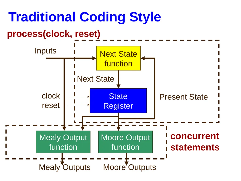
Traditional Coding Style State
Register Next State
function Moore Output
function Inputs Present State Next State clock reset process(clock, reset) concurrent
statements Mealy Output
function Mealy Outputs Moore Outputs<br>
function Moore Output
function Inputs Present State Next State clock reset process(clock, reset) concurrent
statements Mealy Output
function Mealy Outputs Moore Outputs<br>
53
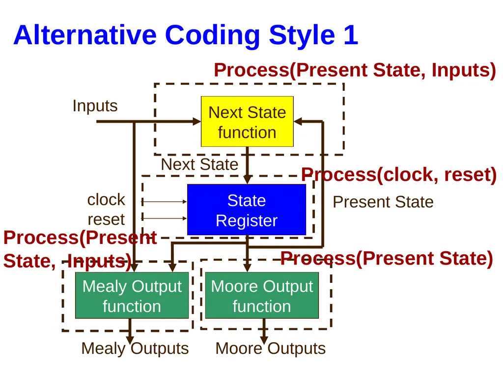
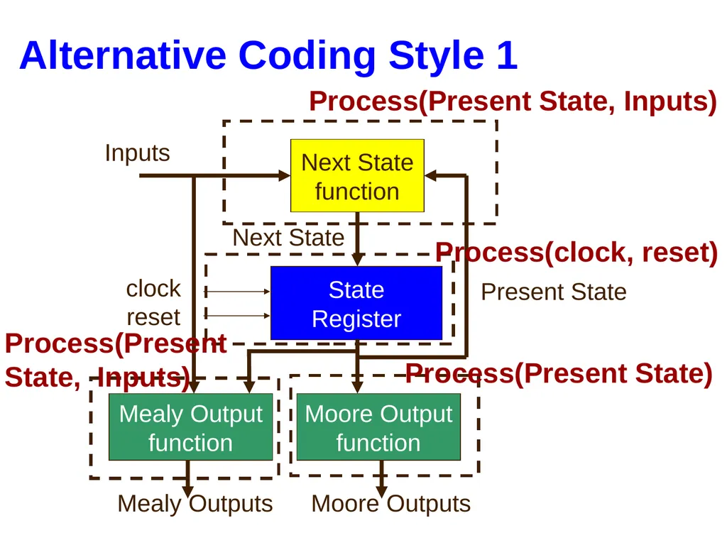
Alternative Coding Style 1 State
Register Next State
function Moore Output
function Inputs Present State Next State clock reset Process(Present State, Inputs) Mealy Output
function Mealy Outputs Moore Outputs Process(clock, reset) Process(Present State) Process(Present
State, Inputs)<br>
function Moore Output
function Inputs Present State Next State clock reset Process(Present State, Inputs) Mealy Output
function Mealy Outputs Moore Outputs Process(clock, reset) Process(Present State) Process(Present
State, Inputs)<br>
54
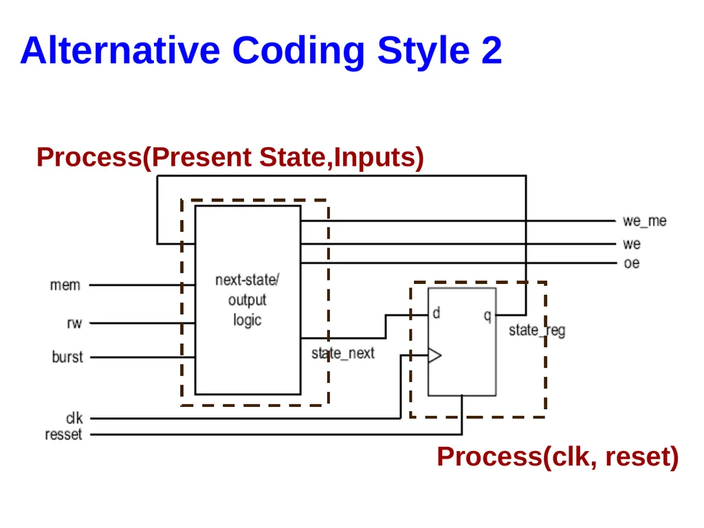
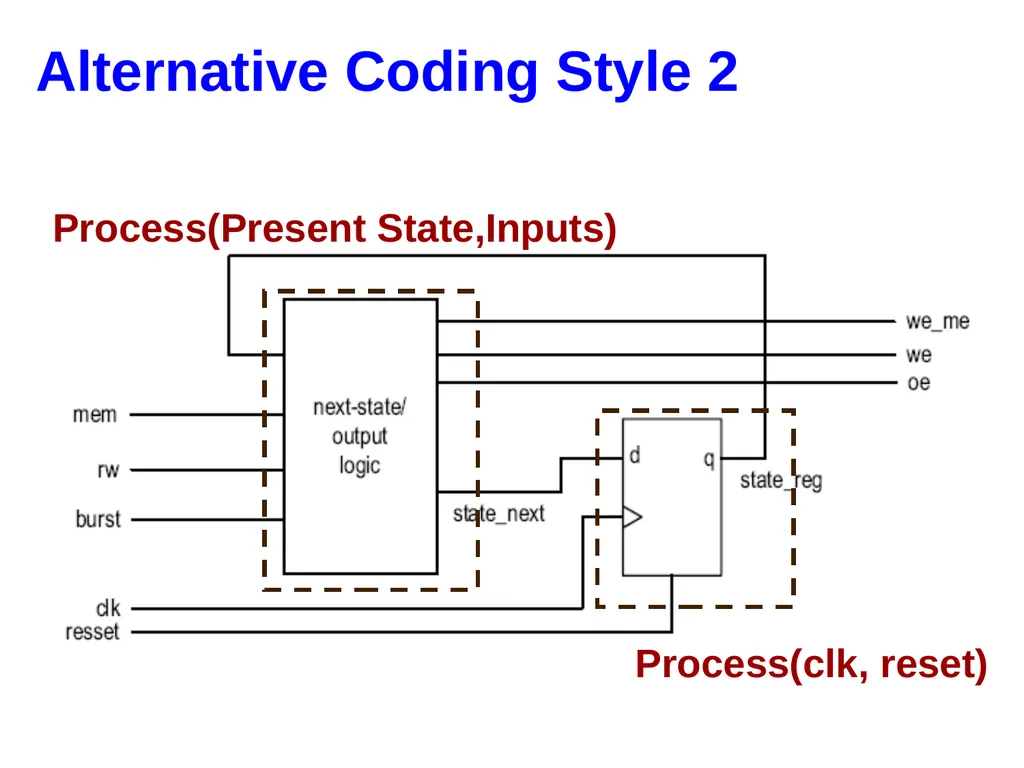
Alternative Coding Style 2 Process(clk, reset) Process(Present State,Inputs)<br>
55
Backup<br>
56
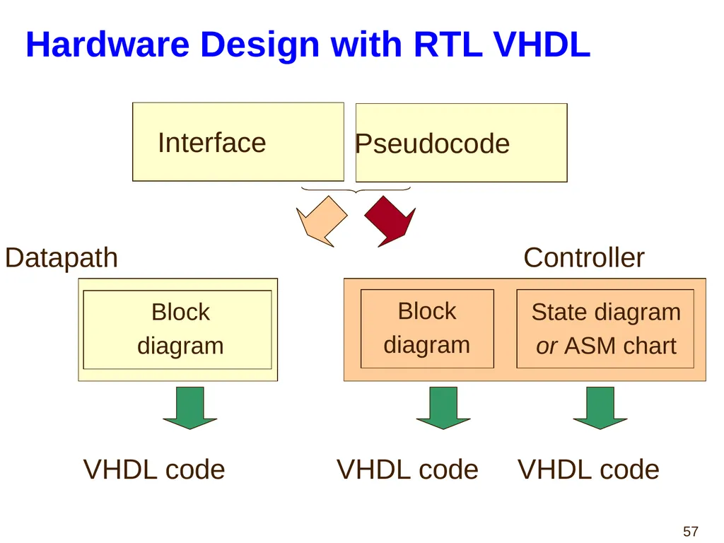
Hardware Design with RTL VHDL Pseudocode Datapath Controller Block
diagram Block
diagram State diagram
or ASM chart VHDL code VHDL code VHDL code Interface<br>
diagram Block
diagram State diagram
or ASM chart VHDL code VHDL code VHDL code Interface<br>
57
Algorithmic State Machine (ASM)
Charts<br>
Charts<br>
58
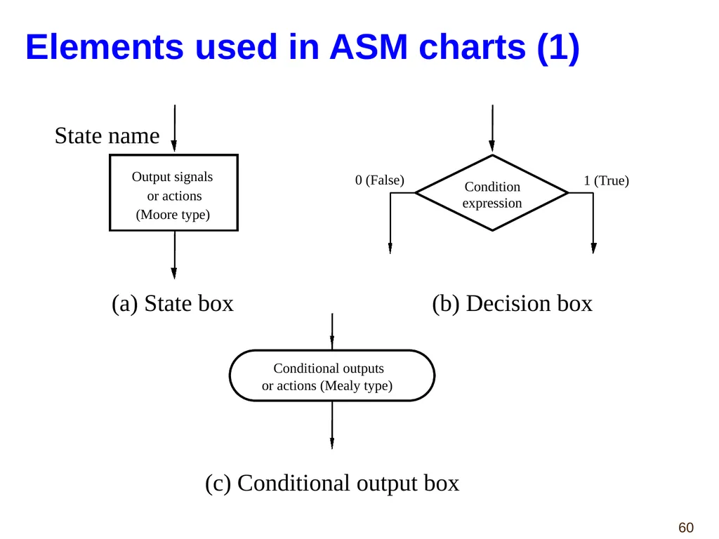
Algorithmic State Machine Algorithmic State Machine –
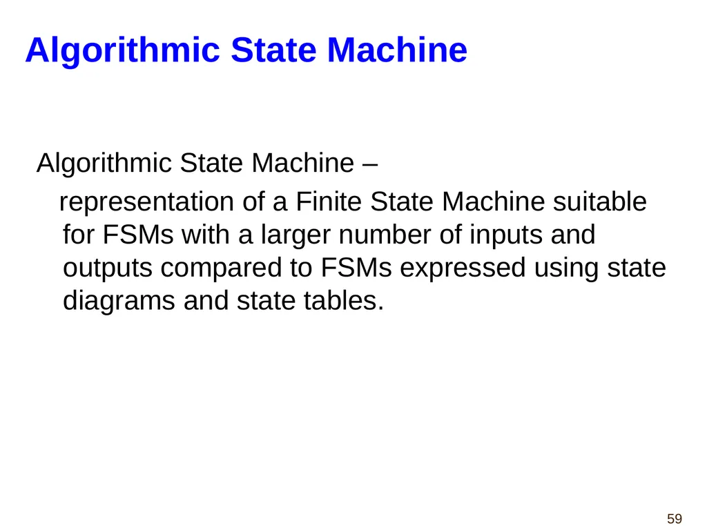
representation of a Finite State Machine suitable for FSMs with a larger number of inputs and outputs compared to FSMs expressed using state diagrams and state tables.<br>
representation of a Finite State Machine suitable for FSMs with a larger number of inputs and outputs compared to FSMs expressed using state diagrams and state tables.<br>
59
Elements used in ASM charts (1) Output signals or actions (Moore type) State name Condition expression 0 (False) 1 (True) Conditional outputs or actions (Mealy type) (a) State box (b) Decision box (c) Conditional output box<br>
60
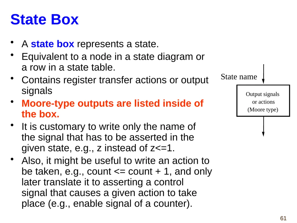
State Box A state box represents a state.
Equivalent to a node in a state diagram or a row in a state table.
Contains register transfer actions or output signals
Moore-type outputs are listed inside of the box.
It is customary to write only the name of the signal that has to be asserted in the given state, e.g., z instead of z<=1.
Also, it might be useful to write an action to be taken, e.g., count <= count + 1, and only later translate it to asserting a control signal that causes a given action to take place (e.g., enable signal of a counter). Output signals or actions (Moore type) State name<br>
Equivalent to a node in a state diagram or a row in a state table.
Contains register transfer actions or output signals
Moore-type outputs are listed inside of the box.
It is customary to write only the name of the signal that has to be asserted in the given state, e.g., z instead of z<=1.
Also, it might be useful to write an action to be taken, e.g., count <= count + 1, and only later translate it to asserting a control signal that causes a given action to take place (e.g., enable signal of a counter). Output signals or actions (Moore type) State name<br>
61
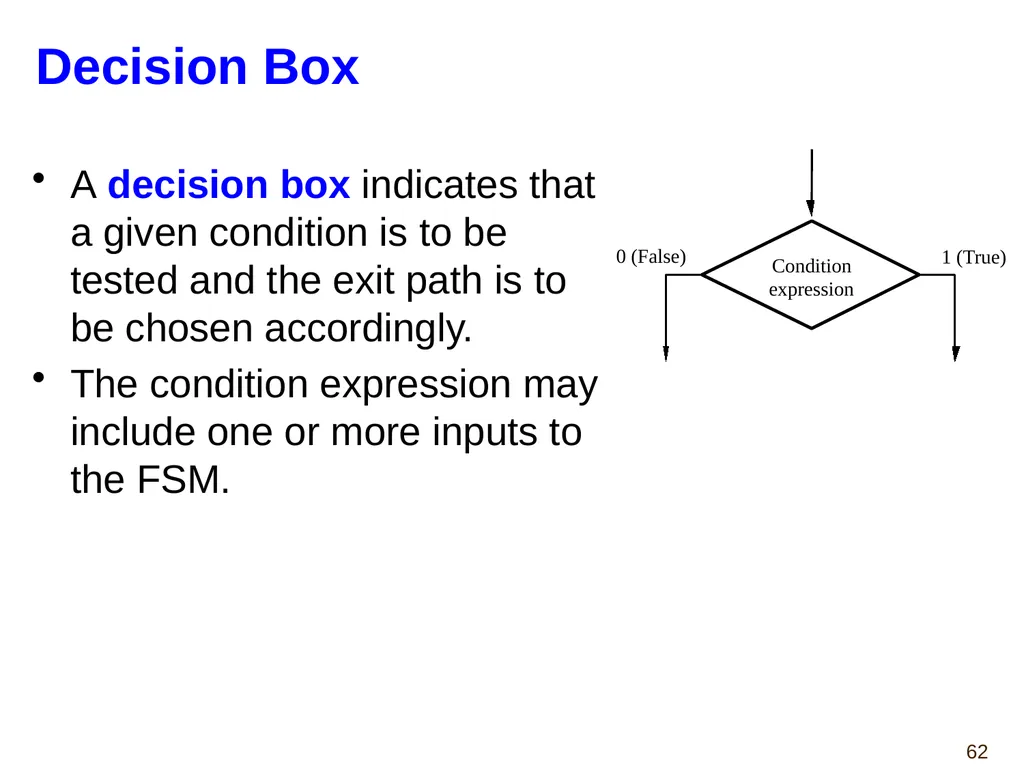
Decision Box A decision box indicates that a given condition is to be tested and the exit path is to be chosen accordingly.
The condition expression may include one or more inputs to the FSM. Condition expression 0 (False) 1 (True)<br>
The condition expression may include one or more inputs to the FSM. Condition expression 0 (False) 1 (True)<br>
62
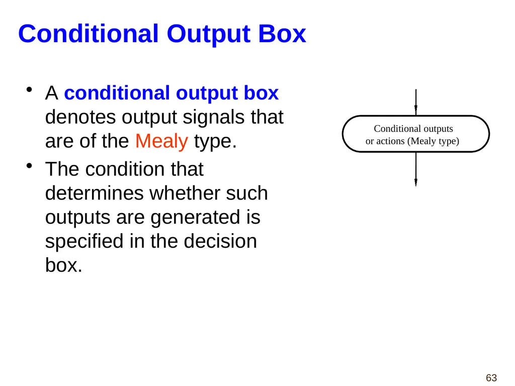
Conditional Output Box A conditional output box denotes output signals that are of the Mealy type.
The condition that determines whether such outputs are generated is specified in the decision box. Conditional outputs or actions (Mealy type)<br>
The condition that determines whether such outputs are generated is specified in the decision box. Conditional outputs or actions (Mealy type)<br>
63
ASMs Representing Simple FSMs Algorithmic state machines can model both Mealy and Moore Finite State Machines
They can also model machines that are of the mixed type.<br>
They can also model machines that are of the mixed type.<br>
64
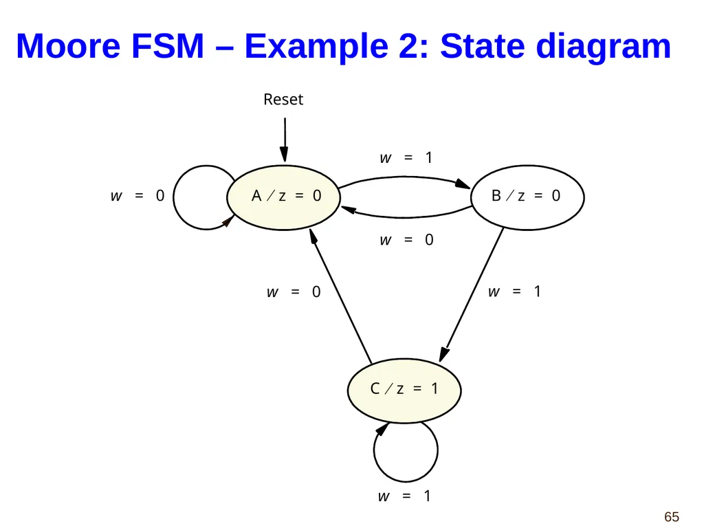
Moore FSM – Example 2: State diagram<br>
65
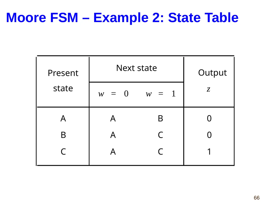
Moore FSM – Example 2: State Table<br>
66
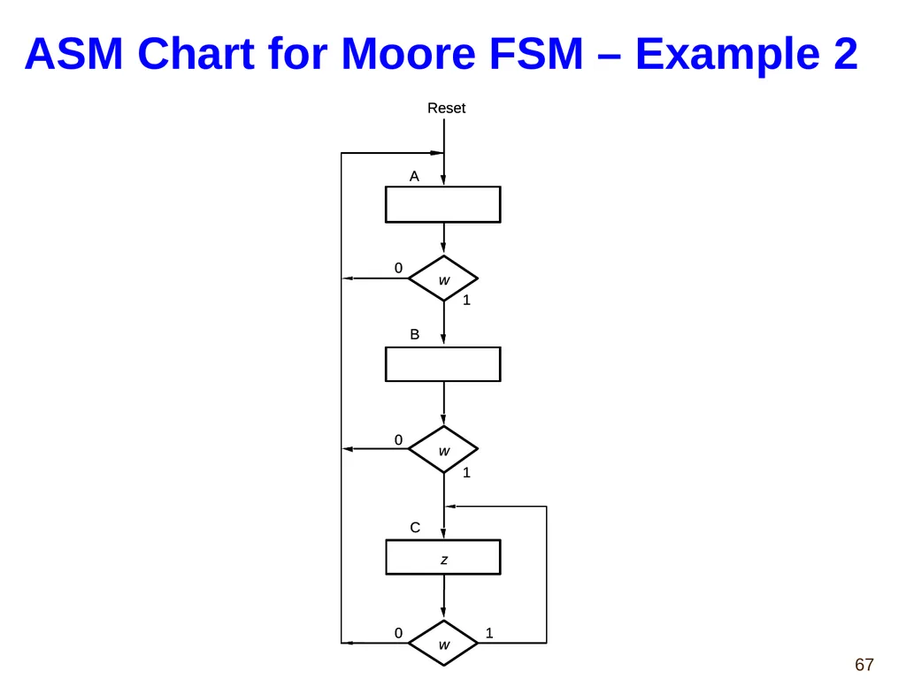
ASM Chart for Moore FSM – Example 2<br>
67
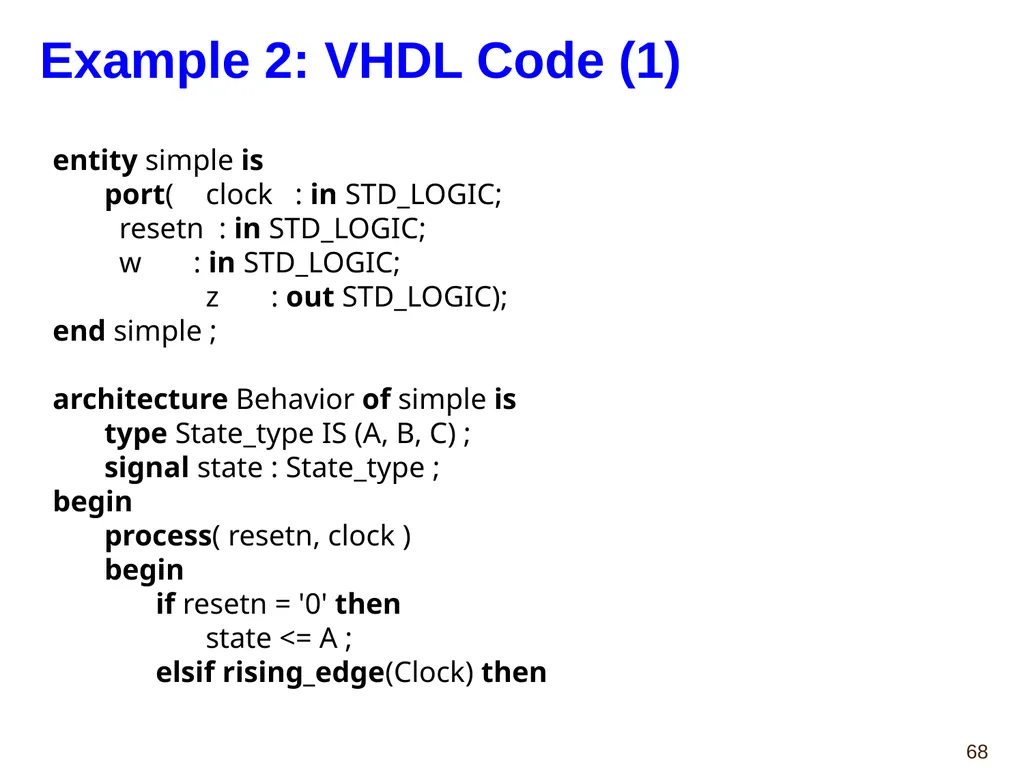
entity simple is
port( clock : in STD_LOGIC;
resetn : in STD_LOGIC;
w : in STD_LOGIC;
z : out STD_LOGIC);
end simple ;
architecture Behavior of simple is
type State_type IS (A, B, C) ;
signal state : State_type ;
begin
process( resetn, clock )
begin
if resetn = '0' then
state <= A ;
elsif rising_edge(Clock) then Example 2: VHDL Code (1)<br>
port( clock : in STD_LOGIC;
resetn : in STD_LOGIC;
w : in STD_LOGIC;
z : out STD_LOGIC);
end simple ;
architecture Behavior of simple is
type State_type IS (A, B, C) ;
signal state : State_type ;
begin
process( resetn, clock )
begin
if resetn = '0' then
state <= A ;
elsif rising_edge(Clock) then Example 2: VHDL Code (1)<br>
68
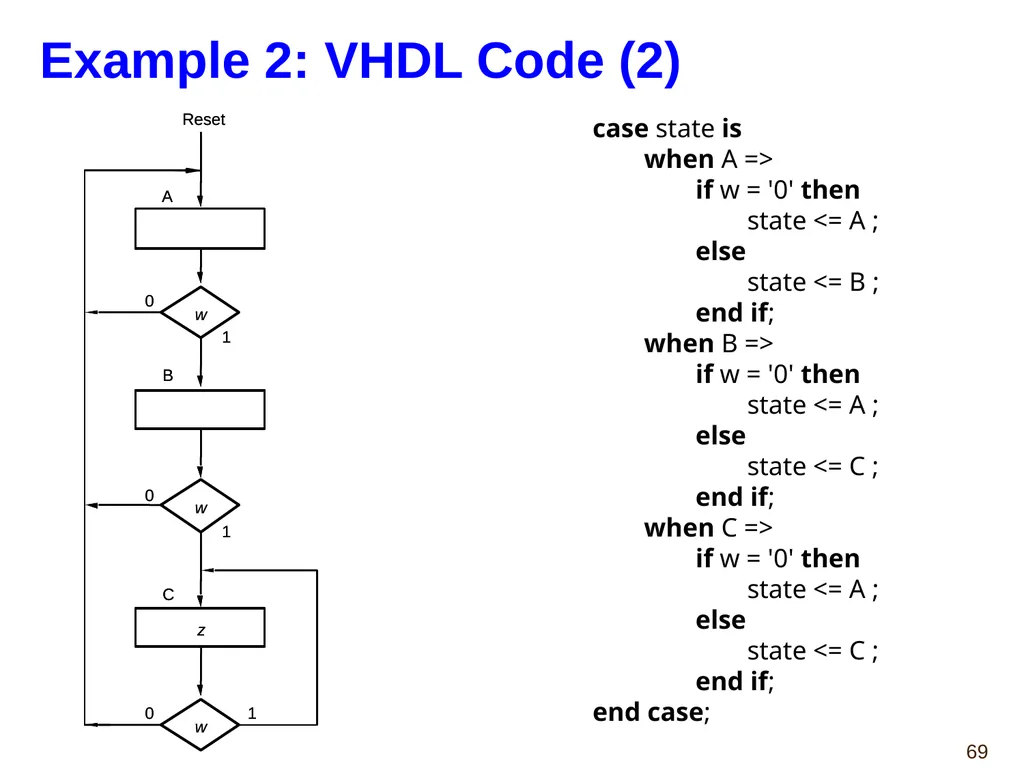
case state is
when A =>
if w = '0' then
state <= A ;
else
state <= B ;
end if;
when B =>
if w = '0' then
state <= A ;
else
state <= C ;
end if;
when C =>
if w = '0' then
state <= A ;
else
state <= C ;
end if;
end case; Example 2: VHDL Code (2)<br>
when A =>
if w = '0' then
state <= A ;
else
state <= B ;
end if;
when B =>
if w = '0' then
state <= A ;
else
state <= C ;
end if;
when C =>
if w = '0' then
state <= A ;
else
state <= C ;
end if;
end case; Example 2: VHDL Code (2)<br>
69
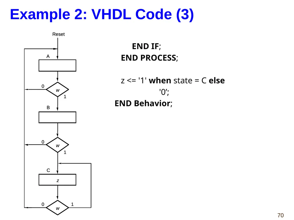
Example 2: VHDL Code (3) END IF;
END PROCESS;
z <= '1' when state = C else
'0’;
END Behavior;<br>
END PROCESS;
z <= '1' when state = C else
'0’;
END Behavior;<br>
70
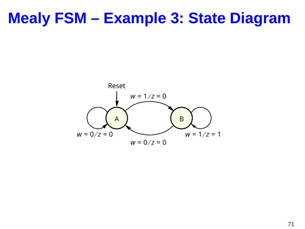
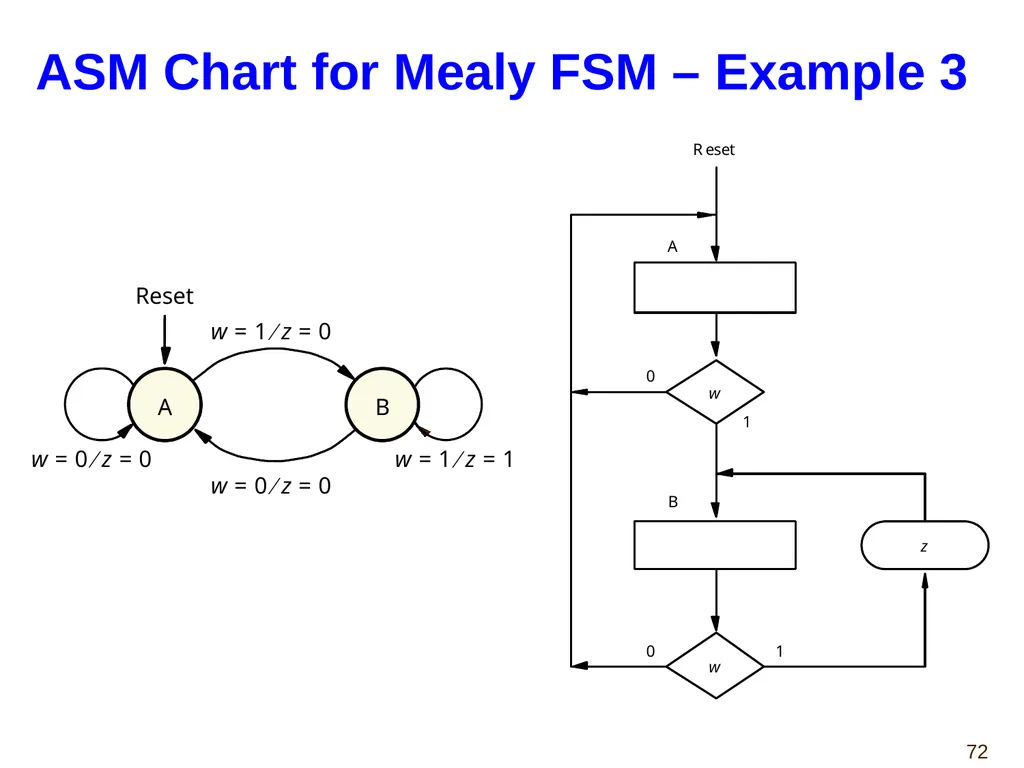
Mealy FSM – Example 3: State Diagram<br>
71
ASM Chart for Mealy FSM – Example 3<br>
72
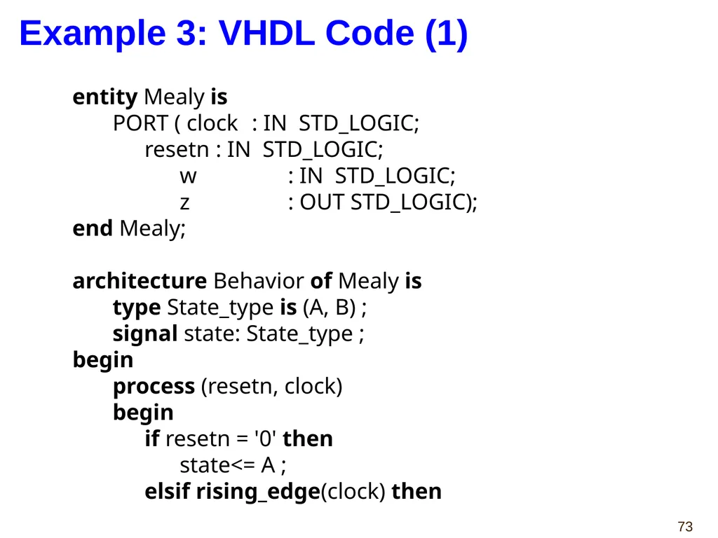
entity Mealy is
PORT ( clock : IN STD_LOGIC;
resetn : IN STD_LOGIC;
w : IN STD_LOGIC;
z : OUT STD_LOGIC);
end Mealy;
architecture Behavior of Mealy is
type State_type is (A, B) ;
signal state: State_type ;
begin
process (resetn, clock)
begin
if resetn = '0' then
state<= A ;
elsif rising_edge(clock) then Example 3: VHDL Code (1)<br>
PORT ( clock : IN STD_LOGIC;
resetn : IN STD_LOGIC;
w : IN STD_LOGIC;
z : OUT STD_LOGIC);
end Mealy;
architecture Behavior of Mealy is
type State_type is (A, B) ;
signal state: State_type ;
begin
process (resetn, clock)
begin
if resetn = '0' then
state<= A ;
elsif rising_edge(clock) then Example 3: VHDL Code (1)<br>
73
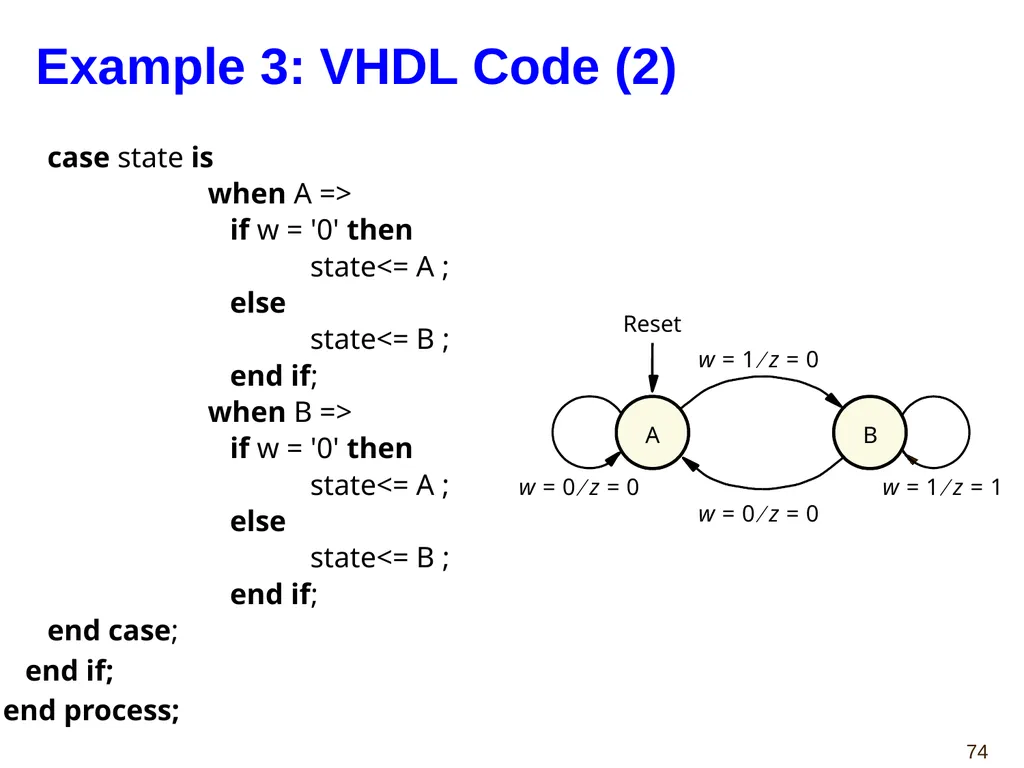
Example 3: VHDL Code (2) case state is
when A =>
if w = '0' then
state<= A ;
else
state<= B ;
end if;
when B =>
if w = '0' then
state<= A ;
else
state<= B ;
end if;
end case;
end if;
end process;<br>
when A =>
if w = '0' then
state<= A ;
else
state<= B ;
end if;
when B =>
if w = '0' then
state<= A ;
else
state<= B ;
end if;
end case;
end if;
end process;<br>
74
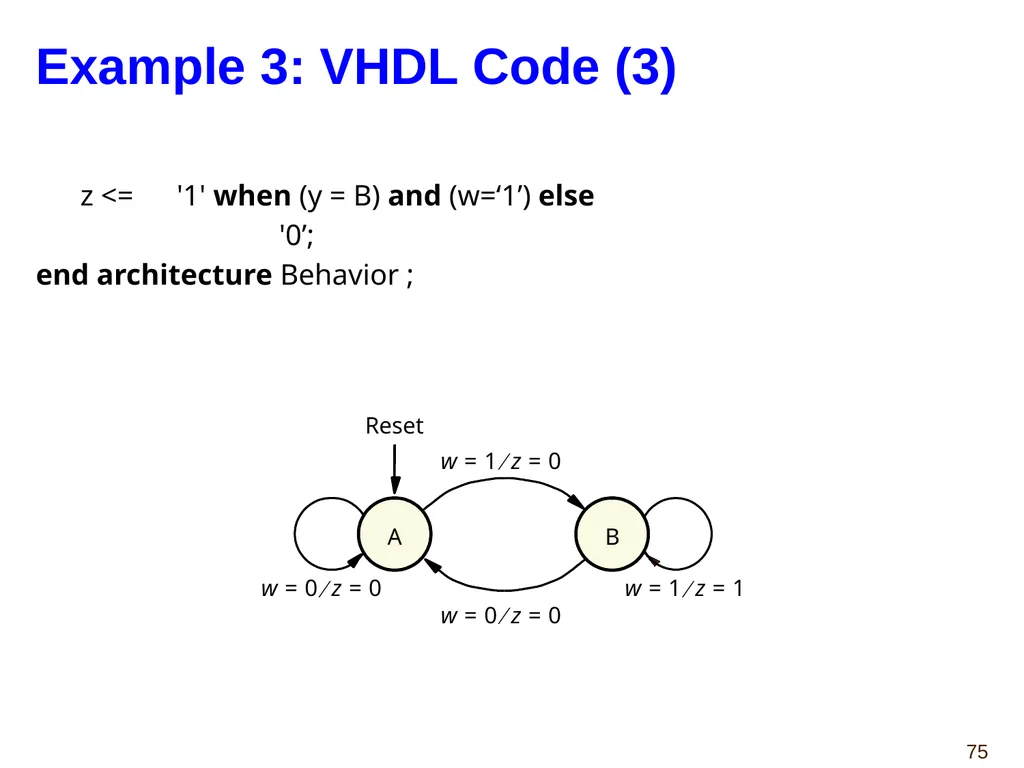
Example 3: VHDL Code (3) z <= '1' when (y = B) and (w=‘1’) else
'0’;
end architecture Behavior ;<br>
'0’;
end architecture Behavior ;<br>
75
Control Unit Example: Arbiter (1) Arbiter reset r1 r2 r3 g1 g2 g3 clock<br>
76
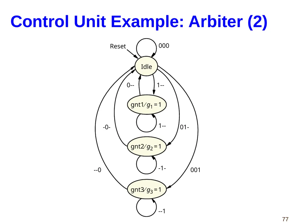
Control Unit Example: Arbiter (2)<br>
77
Control Unit Example: Arbiter (3)<br>
78
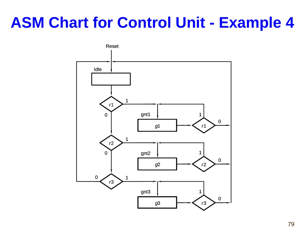
ASM Chart for Control Unit - Example 4<br>
79
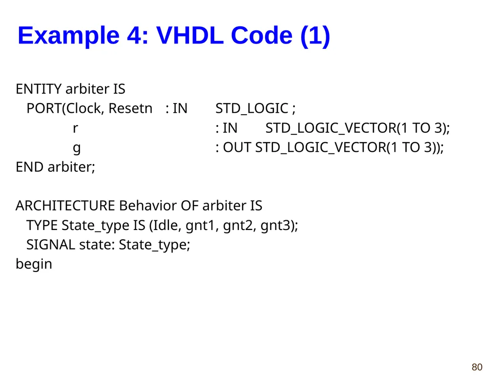
Example 4: VHDL Code (1) ENTITY arbiter IS
PORT(Clock, Resetn : IN STD_LOGIC ;
r : IN STD_LOGIC_VECTOR(1 TO 3);
g : OUT STD_LOGIC_VECTOR(1 TO 3));
END arbiter;
ARCHITECTURE Behavior OF arbiter IS
TYPE State_type IS (Idle, gnt1, gnt2, gnt3);
SIGNAL state: State_type;
begin<br>
PORT(Clock, Resetn : IN STD_LOGIC ;
r : IN STD_LOGIC_VECTOR(1 TO 3);
g : OUT STD_LOGIC_VECTOR(1 TO 3));
END arbiter;
ARCHITECTURE Behavior OF arbiter IS
TYPE State_type IS (Idle, gnt1, gnt2, gnt3);
SIGNAL state: State_type;
begin<br>
80
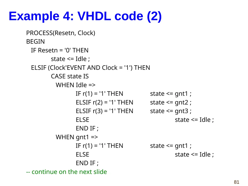
Example 4: VHDL code (2) PROCESS(Resetn, Clock)
BEGIN
IF Resetn = '0' THEN
state <= Idle ;
ELSIF (Clock'EVENT AND Clock = '1') THEN
CASE state IS
WHEN Idle =>
IF r(1) = '1' THEN state <= gnt1 ;
ELSIF r(2) = '1' THEN state <= gnt2 ;
ELSIF r(3) = '1' THEN state <= gnt3 ;
ELSE state <= Idle ;
END IF ;
WHEN gnt1 =>
IF r(1) = '1' THEN state <= gnt1 ;
ELSE state <= Idle ;
END IF ;
-- continue on the next slide<br>
BEGIN
IF Resetn = '0' THEN
state <= Idle ;
ELSIF (Clock'EVENT AND Clock = '1') THEN
CASE state IS
WHEN Idle =>
IF r(1) = '1' THEN state <= gnt1 ;
ELSIF r(2) = '1' THEN state <= gnt2 ;
ELSIF r(3) = '1' THEN state <= gnt3 ;
ELSE state <= Idle ;
END IF ;
WHEN gnt1 =>
IF r(1) = '1' THEN state <= gnt1 ;
ELSE state <= Idle ;
END IF ;
-- continue on the next slide<br>
81
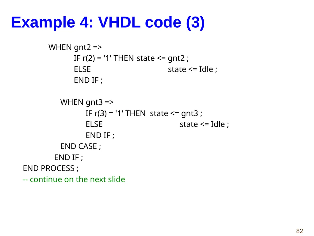
Example 4: VHDL code (3) WHEN gnt2 =>
IF r(2) = '1' THEN state <= gnt2 ;
ELSE state <= Idle ;
END IF ;
WHEN gnt3 =>
IF r(3) = '1' THEN state <= gnt3 ;
ELSE state <= Idle ;
END IF ;
END CASE ;
END IF ;
END PROCESS ;
-- continue on the next slide<br>
IF r(2) = '1' THEN state <= gnt2 ;
ELSE state <= Idle ;
END IF ;
WHEN gnt3 =>
IF r(3) = '1' THEN state <= gnt3 ;
ELSE state <= Idle ;
END IF ;
END CASE ;
END IF ;
END PROCESS ;
-- continue on the next slide<br>
82
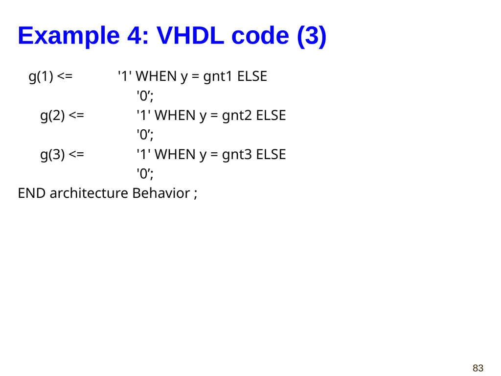
Example 4: VHDL code (3) g(1) <= '1' WHEN y = gnt1 ELSE
'0’;
g(2) <= '1' WHEN y = gnt2 ELSE
'0’;
g(3) <= '1' WHEN y = gnt3 ELSE
'0’;
END architecture Behavior ;<br>
'0’;
g(2) <= '1' WHEN y = gnt2 ELSE
'0’;
g(3) <= '1' WHEN y = gnt3 ELSE
'0’;
END architecture Behavior ;<br>
83
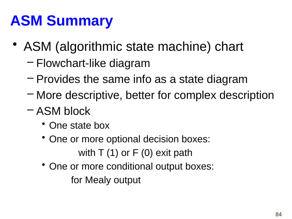
ASM Summary ASM (algorithmic state machine) chart
Flowchart-like diagram
Provides the same info as a state diagram
More descriptive, better for complex description
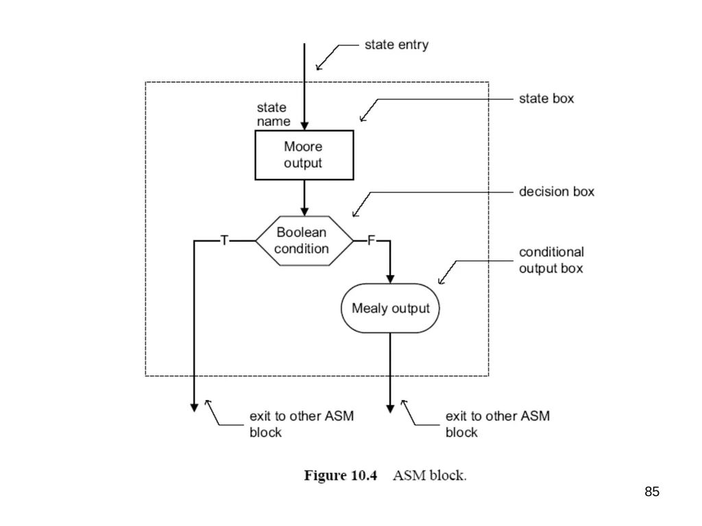
ASM block
One state box
One or more optional decision boxes:
with T (1) or F (0) exit path
One or more conditional output boxes:
for Mealy output<br>
Flowchart-like diagram
Provides the same info as a state diagram
More descriptive, better for complex description
ASM block
One state box
One or more optional decision boxes:
with T (1) or F (0) exit path
One or more conditional output boxes:
for Mealy output<br>
84
85<br>
85
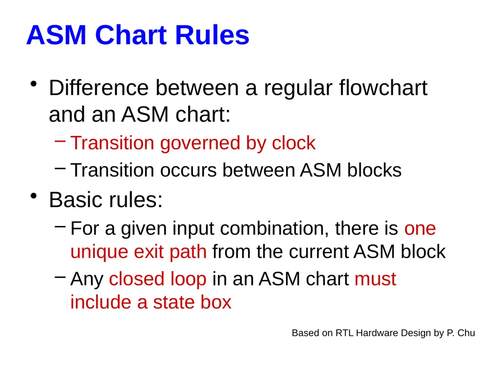
ASM Chart Rules Based on RTL Hardware Design by P. Chu Difference between a regular flowchart and an ASM chart:
Transition governed by clock
Transition occurs between ASM blocks
Basic rules:
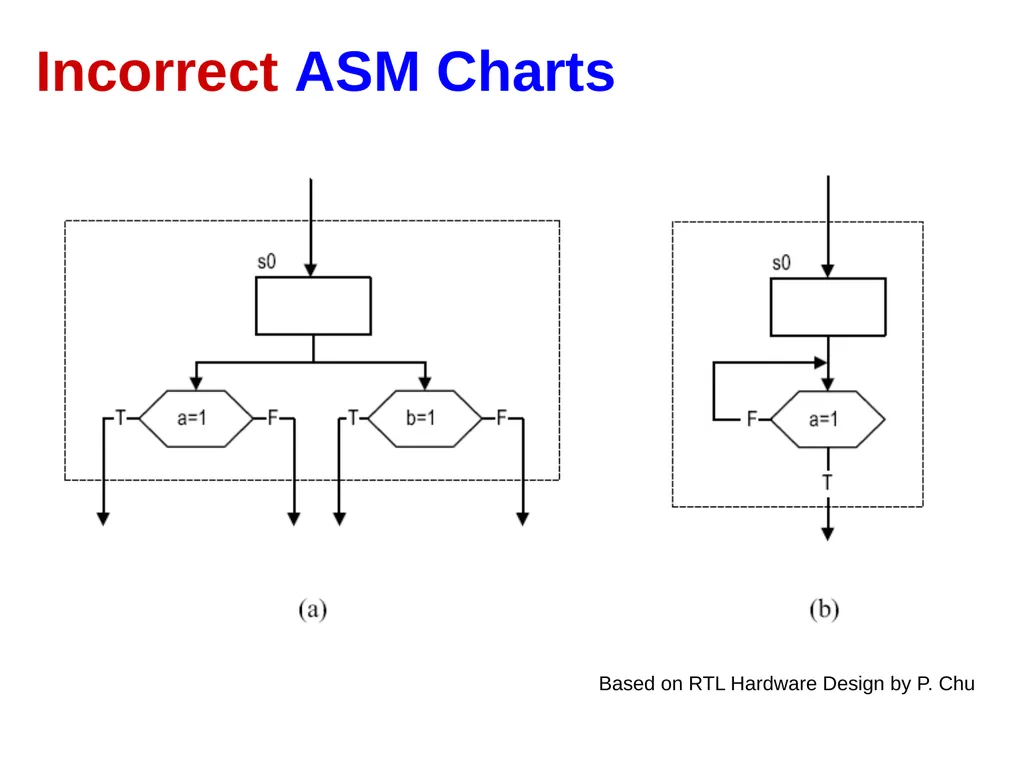
For a given input combination, there is one unique exit path from the current ASM block
Any closed loop in an ASM chart must include a state box<br>
Transition governed by clock
Transition occurs between ASM blocks
Basic rules:
For a given input combination, there is one unique exit path from the current ASM block
Any closed loop in an ASM chart must include a state box<br>
86
Incorrect ASM Charts Based on RTL Hardware Design by P. Chu<br>
87
Alternative Coding Styles
by Dr. Chu
(to be used with caution)<br>
by Dr. Chu
(to be used with caution)<br>
88
Traditional Coding Style State
Register Next State
function Moore Output
function Inputs Present State Next State clock reset process(clock, reset) concurrent
statements Mealy Output
function Mealy Outputs Moore Outputs<br>
function Moore Output
function Inputs Present State Next State clock reset process(clock, reset) concurrent
statements Mealy Output
function Mealy Outputs Moore Outputs<br>
89
Alternative Coding Style 1 State
Register Next State
function Moore Output
function Inputs Present State Next State clock reset Process(Present State, Inputs) Mealy Output
function Mealy Outputs Moore Outputs Process(clock, reset) Process(Present State) Process(Present
State, Inputs)<br>
function Moore Output
function Inputs Present State Next State clock reset Process(Present State, Inputs) Mealy Output
function Mealy Outputs Moore Outputs Process(clock, reset) Process(Present State) Process(Present
State, Inputs)<br>
90
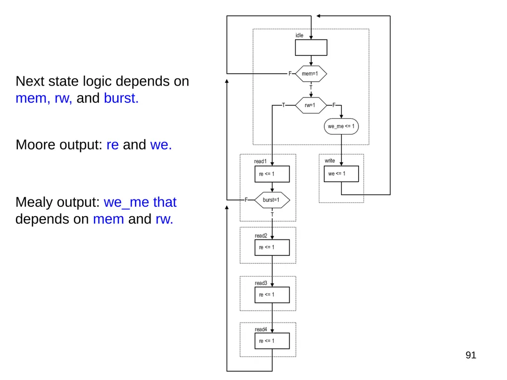
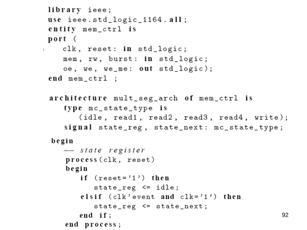
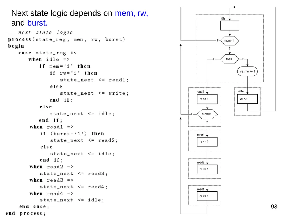
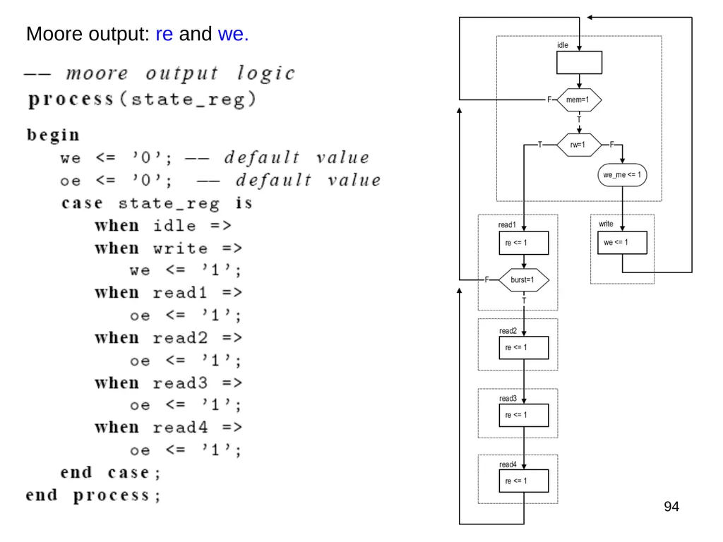
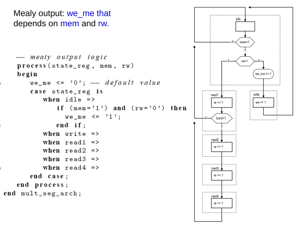
91 Next state logic depends on mem, rw, and burst. Moore output: re and we. Mealy output: we_me that depends on mem and rw.<br>
91
92<br>
92
93 Next state logic depends on mem, rw, and burst.<br>
93
94 Moore output: re and we.<br>
94
95 Mealy output: we_me that depends on mem and rw.<br>
95
Alternative Coding Style 2 Process(clk, reset) Process(Present State,Inputs)<br>
96
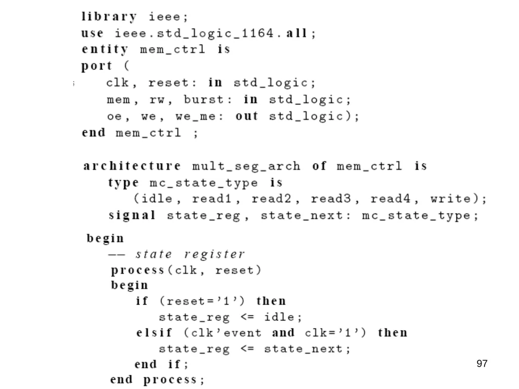
97<br>
97
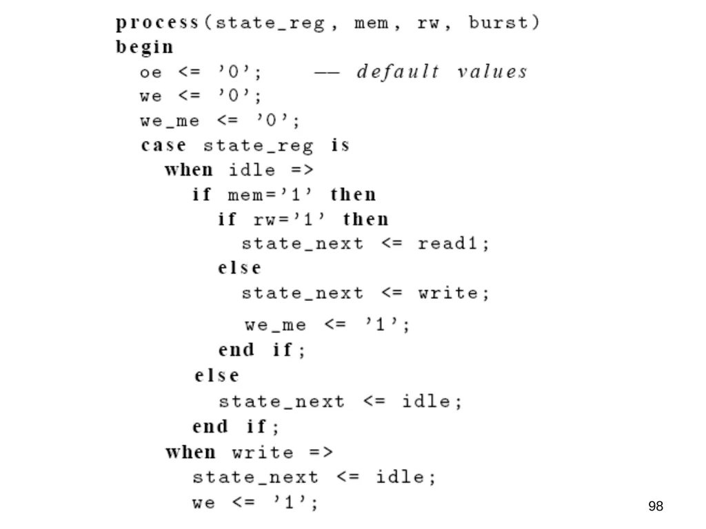
98<br>
98
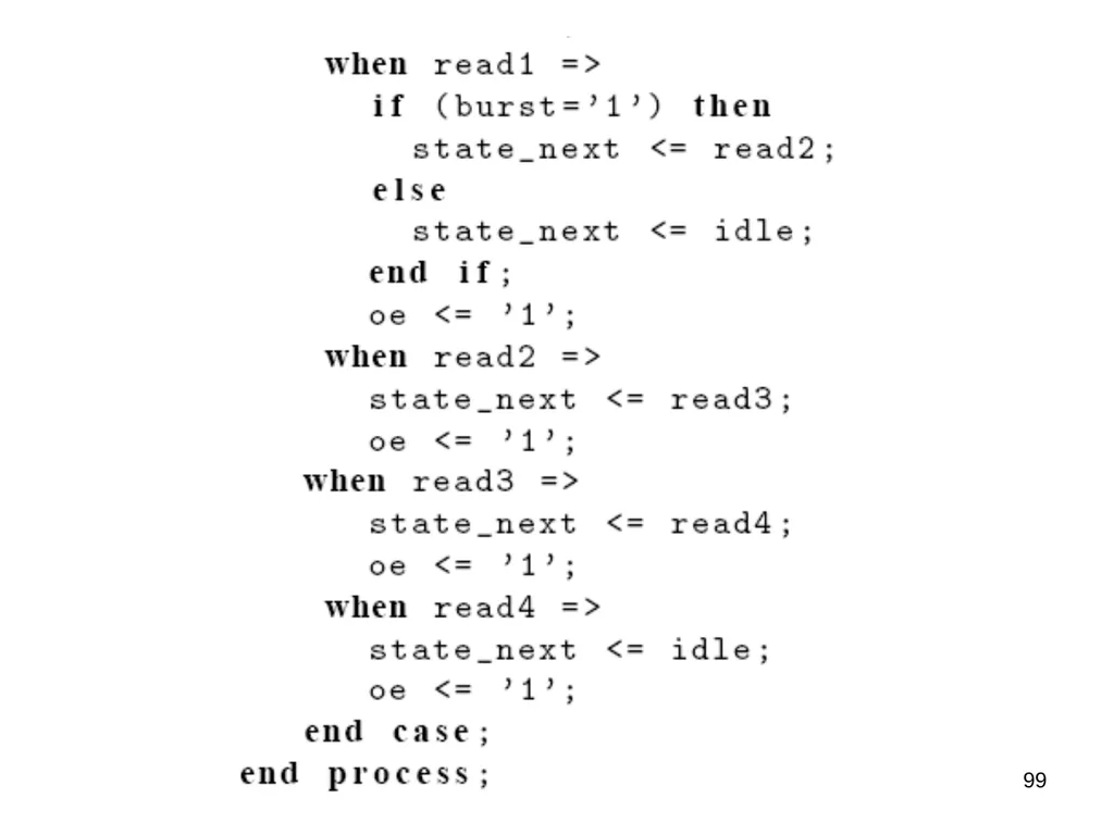
99<br>