Interrupt Processing Sequence The X86 processors have 256 software interrupts, with initially operate similar to CALL instruction. When INT n instruction is executed, Visit for more Learning Resources When INT n instruction is executed 1.
"Interrupt Processing Sequence The X86 processors" is the property of its rightful owner. Permission is granted to
download and print the materials on this website for personal, non-commercial use only, and to display it
on your personal computer provided you do not modify the materials and that you retain all copyright
notices contained in the materials. By downloading content from our website, you accept the terms of this
agreement.
Presentation Transcript
01
Interrupt Processing Sequence The X86 processors have 256 software interrupts, with initially operate similar to CALL instruction.
When INT n instruction is executed, Visit for more Learning Resources<br>
02
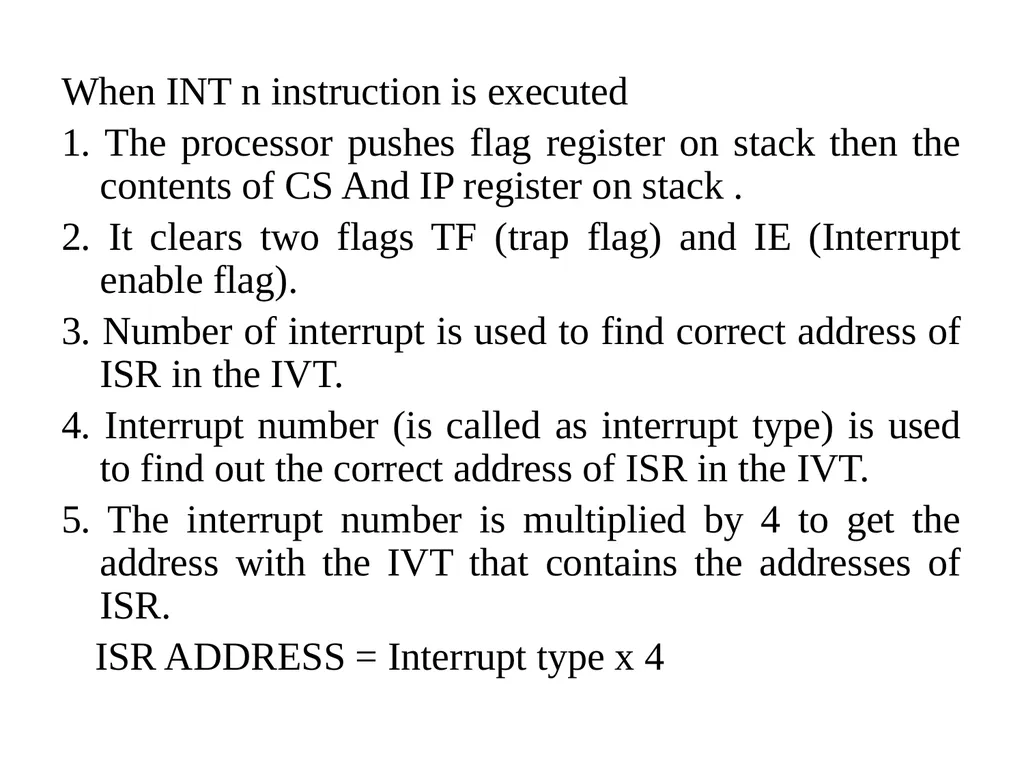
When INT n instruction is executed
1. The processor pushes flag register on stack then the contents of CS And IP register on stack .
2. It clears two flags TF (trap flag) and IE (Interrupt enable flag).
3. Number of interrupt is used to find correct address of ISR in the IVT.
4. Interrupt number (is called as interrupt type) is used to find out the correct address of ISR in the IVT.
5. The interrupt number is multiplied by 4 to get the address with the IVT that contains the addresses of ISR.
ISR ADDRESS = Interrupt type x 4<br>
03
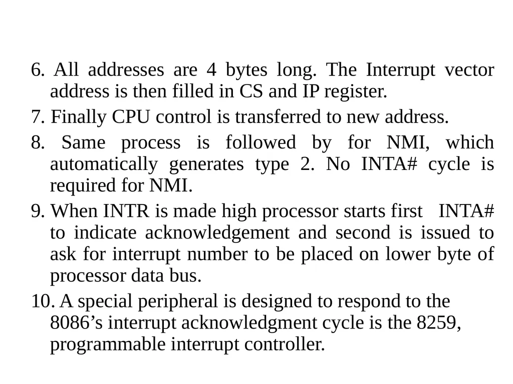
6. All addresses are 4 bytes long. The Interrupt vector address is then filled in CS and IP register.
7. Finally CPU control is transferred to new address.
8. Same process is followed by for NMI, which automatically generates type 2. No INTA# cycle is required for NMI.
9. When INTR is made high processor starts first INTA# to indicate acknowledgement and second is issued to ask for interrupt number to be placed on lower byte of processor data bus.
10. A special peripheral is designed to respond to the 8086’s interrupt acknowledgment cycle is the 8259, programmable interrupt controller.<br>
04
Special Interrupts of X86 Divide by zero Error:
Single step: When a trap/trace flag in the flag reg. is set, processor generates a type-1 interrupt after the execution of each instruction.
So, this interrupt can be used for debugging a program by writing ISR as a single step debugger to display the contents of register, the state of flag register and other useful information for the programmer on the screen.<br>
05
NMI: NMI can never be ignore by the processor, so it is useful in event that the computer absolutely must be respond such as event is the disastrous Power fail.
The processor lost the contents of its registers and flags when power is turned off and thus there is a no chance to getting back to the correct place in a program if its power is uninterrupted.
So, in the vent of a power fail, the NMI ISR should store the contents of each processor register in the NV RAM and then these values can then be reloaded when power comes back.<br>
06
Break Point: Break point interrupt is a type-3 interrupt, but is coded as a single byte for reasons of efficiency.
Break point is used in debugging, a program being debugged will have the first byte of one of its instructions replaced by the code for break point.
When the processor gets to this instruction, then processor generate a type-3 interrupt and the ISR associated with breakpoint is similar to the trace/ trap ISR and is used for displaying the processor register contents and also the address at which the breakpoint occurred.
Before ISR exists, it will replace the breakpoint byte with the original first byte of the instruction.<br>
07
Overflow: This type-4 interrupt is activated only when the INTO instruction is executed with the overflow flag set.
Its application, like divide-error, end to be of a corrective nature.<br>
08
Performance issues in pipeline systems. Pipelining increases the CPU instruction throughput - the number of instructions completed per unit of time. But it does not reduce the execution time of an individual instruction. In fact, it usually slightly increases the execution time of each instruction due to overhead in the pipeline control.
The increase in instruction throughput means that a program runs faster and has lower total execution time.<br>
09
Limitations on practical depth of a pipeline arise from:
Instruction latency: A poorly designed set can cause a pipelined processor to stall frequently. Some of the more typical CISC instruction which have more instruction latency should avoided.
Dependency Issues: Dependence on single point resource such as a condition code register. If one instruction sets the conditions in the condition code register and the following instruction tries to read those bits, the second instruction may have to stall until the first instruction's write completes.<br>
10
Cautions on the use of RISC: The transition from CISC to RISC design strategy is, not without its problem. The software engineers should be aware of the key issues which arises when moving code from a CISC processor to a RISC
Imbalance among pipeline stages. Imbalance among the pipe stages reduces performance since the clock can run no faster than the time needed for the slowest pipeline stage. For more detail contact us<br>