
ITEC 275 Computer Networks – Switching, Routing,








Description: ITEC 275 Computer Networks Switching, Routing, and WANs Week 1 Agenda Introductions Review policies, procedures, and expected outcomes Learning Activities Introduce homework problems Location of Power Point presentations
Related Topics
Download Presentation
"ITEC 275 Computer Networks – Switching, Routing," is the property of its rightful owner. Permission is granted to download and print the materials on this website for personal, non-commercial use only, and to display it on your personal computer provided you do not modify the materials and that you retain all copyright notices contained in the materials. By downloading content from our website, you accept the terms of this agreement.
Presentation Transcript
slide1. ITEC 275
Computer Networks – Switching, Routing, and WANs Week 1<br>
slide2. Agenda Introductions
Review policies, procedures, and expected outcomes
Learning Activities
Introduce homework problems
Location of Power Point presentations
http://cs.franklin.edu/~dandrear/itec275/Fall_2013_Network_Presentations/Week_One_Network_ppt or .pptx<br>
slide3. Introductions Professor Robert D’Andrea
Adjunct faculty at Franklin
Teaching ITEC275 and ITEC 400
Cell phone 614.519.5853
Industry experience in security, systems administration, networking, software development, and deployment of software and hardware.<br>
slide4. Introductions Program Chair Information Technology Security
Professor Brad Reed
Brad.reed@franklin.edu
Cell phone 614.918.8321
Writing doctorate dissertation on Information Technology Security.<br>
slide5. Introductions Now your turn:
Name
Major
Interest level and experience in networking
Goal for this class<br>
slide6. Administration Principles of Computer Networks
Prerequisites: College Writing (COMM 120), and Principles of Computer Networks (COMP 204), or A Networking Fundamentals course.
This course serves as an introduction to the function, design, administration, and implementation of computer networks. Topics include network infrastructure, architecture, protocols, applications, and the OSI networking model.<br>
slide7. Administration Course Outcomes
Diagram an end-to-end network communication path, describing each intermediate step.
Design a small-scale network configuration, including addressing, routing, and switching.
Describe the functions of the TCP/IP and Ethernet protocols including select fields, flags, options, headers, and trailers for both.<br>
slide8. Administration Course Outcomes (ctd)
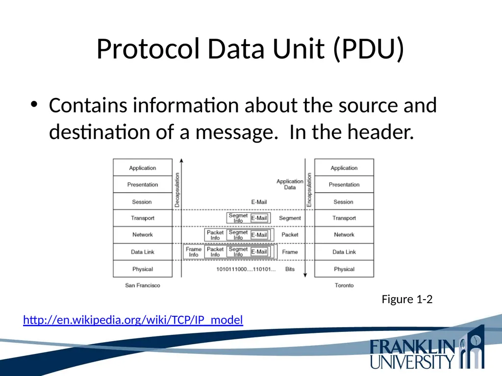
Distinguish between types of data elements (segments, packets, frames, and bits).
Map the key elements of the TCP/IP protocol suite to the OSI model.<br>
slide9. Administration Text
Oppenheimer, P. (2011). Top-Down Network Design: A systems analysis approach to enterprise network design. (3rd ed.). Indianapolis, IN: Cisco Press. ISBN: 978-1-58720-283-4.<br>
slide10. Administration Academic integrity
Items on the Web can serve as “inspiration” for your solutions if:
You understand the solution as if you had written it yourself.
You cite your source of inspiration
Not citing your source can get you charged with cheating/plagiarism.<br>
slide11. Administration Academic integrity
Items on the Web can serve as “inspiration” for your solutions if:
You understand the solution as if you had written it yourself.
You cite your source of inspiration
Not citing your source can get you charged with cheating/plagiarism. Note: if a homework problem says “research X,” or “investigate Y,” then I’m expecting a citation! Technically, you should cite your textbook on almost every HW assignment.<br>
slide12. Administration Academic integrity
Other students cannot serve as a source for your “inspiration!"
The closer you move toward sharing answers with or soliciting answers from another person (student or not), the more likely it is that you are cheating.<br>
slide13. Administration Academic integrity
If you have a vague feeling that you wouldn’t want your instructor to know about what you’re doing… don’t do it.
When in doubt, ask your instructor.<br>
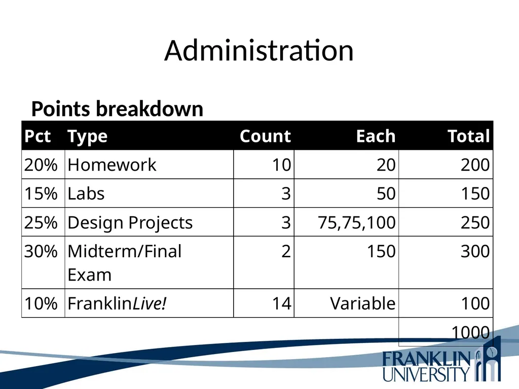
slide14. Administration Points breakdown<br>
slide15. Daily/weekly Activities Daily: Check announcements and e-mail lists
Before class
Read the associated sections from the text books and key points
Read and consider the weekly homework problems
After class
Complete the homework assignment
Work on any scheduled lab assignments
Note significant learning<br>
slide16. Course Outcomes Upon successful completion of this course students will be able to:
Determine an appropriate approach to design a network based on customer needs and consideration of financial and technological constraints.
Identify the design considerations and tradeoffs for campus, WAN, and data center infrastructure models.
Select appropriate WAN components used in a standard WAN architecture.
Compare and contrast routing and addressing schemas and the mechanisms for implementing each one.
Identify and describe the components and standards used for implementing telephony into a data network.
Configure routers and switches using Cisco IOS commands.
Effectively communicate how a network design plan meets a customer's connectivity needs.<br>
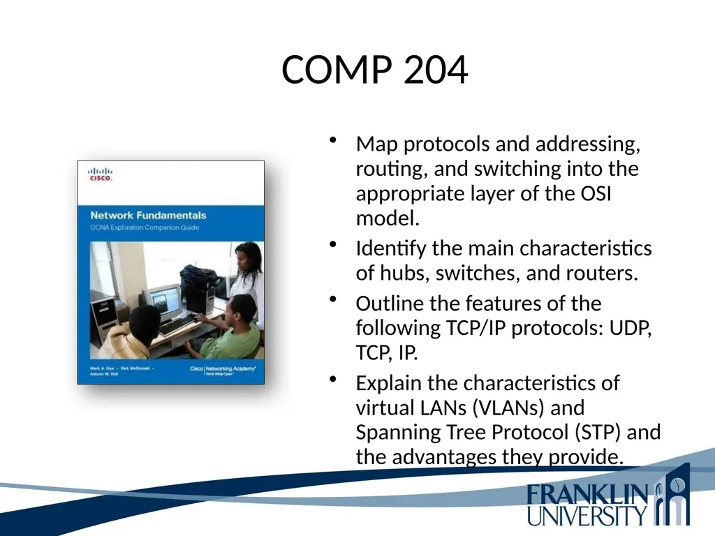
slide17. COMP 204 Map protocols and addressing, routing, and switching into the appropriate layer of the OSI model.
Identify the main characteristics of hubs, switches, and routers.
Outline the features of the following TCP/IP protocols: UDP, TCP, IP.
Explain the characteristics of virtual LANs (VLANs) and Spanning Tree Protocol (STP) and the advantages they provide.<br>
slide18. Top-Down Network Design Analyze your customers business goals
Business goals are the capability to run network applications to meet an organizations business objectives, within the business constraints. These constraints could be limited network personnel, budgets, and limited timeframe.
Good network design subscribes to the customers requirements to the letter. This would include business and technical goals, requirements for availability, scalability, affordability, manageability, and security needs. Some customers will specify a required level of network performance, referred to as service level.
When a customer wants a quick fix design, it is referred to as a bottom-up network design. Associated with this type of design is unexpected scalability, poor performance, and does not meet the customers most important needs.
Top-down network design is a methodology for designing networks at the upper layers of the OSI model before referring to lower layers (devices, cabling, and switch configurations).
Top-down network design includes exploring organizational and group structures to find individuals the network is being designed to provide a services and from whom the design should get valuable information to make the design a success.<br>
slide19. Top-Down Network Design Top-down network design is iterative. Initially, it is important to get the overall view of the customers requirements. Later, after digesting the high abstractions of the design, then focus on the finer details of the design like protocol behavior, scalability requirements, and technology preferences. Top-down network design recognizes that the logical model and the physical design can change as more information becomes available.
A top-down network design approach enables the designer to obtain “the big picture” initially, and the drilling down for specifics requirements and technical details.
Top-down network design is a methodology the grew out of structured software programming and structured systems analysis.
Top-down network design divides the project up into small logical pieces known as modules. These modules allow large projects to be more manageable and easier to debug.<br>
slide20. Top-Down Network Design Modules are split into logical functions.
A top-down network design approach is divided into four major phases and are carried out in a cyclical fashion:
Analyze requirements - interview users and technical personal to gain an understanding of their business and technical goals for new or existing networks.
Develop the logical design – logical topology for the new or existing network, security, switching, routing protocols.
Develop the physical design – This phase addresses the specific technologies and products that are realized in the logical design are selected.
Test, optimize, and document the design – update the documentation that represents the network design, create test scenario, build a prototype or pilot network, optimize the network design.
The major phases of the top-down network design repeats itself. The user and the network monitoring suggest enhancements or the need for new specifications.<br>
slide21. Top-Down Network Design Network Design Plan Life Cycle
Plan – Identify the network requirements in this phase.
Design – Complete the bulk of the logical and physical design.
Implement – Implement the building of the proposed network design.
Operate – Final test the effectiveness of the network design. This includes monitoring the network and services.
Optimize – This phase is based on actual operations. Identifying and resolving problems that were encountered.
Retire – When part or the whole network design no longer meets the needs of the company and users, this should be an avenue of consideration. This component is not officially part of the life cycle model.
Plan Design Implement Operate Optimize (PDIOO) Network Life Cycle.<br>
slide22. Top-Down Network Design Network Design Components
Analyzing Business Goals – knowing your customers business goals and constraints. With a thorough understanding of your customers business objectives, you will be able to provide a network design that will meet your customers approval.
Working with Your Client – Research the type of business your client is in before meeting with them. Learn all that you can about his or her market, suppliers, services, and competitive advantage.
Changes in Enterprise Network – Internal users is limited for todays network needs. Your customer now has to think about remote entries both domestically, mobile access, RFS, and globally. Security is a topic that cannot be underestimated in our current network environment.
Network Must Make Sense – Business leaders today are more involved with IT decisions than past administrations. Customers want to operate leaner in data center personnel, power usage, and technology for technology’s sake.,<br>
slide23. Top-Down Network Design Network Design Components
Networks Offer a service – IT departments are more service oriented than they use to be in the past.
Governance refers to a focus on consistent, cohesive, policies, and processes that protect an organization from mismanagement and illegal operations of users of IT services.
Compliance refers to adherence to regulations that protect against fraud and the disclosure of private customer data.
Need to Support Mobile Users – Network users expect network performance to be uniform , regardless of where the user or data resides.
The Importance of Network Security and Resiliency – Enterprises have to protect themselves from internal, web, and external from more areas than past environments.
Typical Network Design Business Goals – listed on pages 13 and 14.<br>
slide24. Top-Down Network Design Identify the scope of the network design project.
Small in scope – sales staff might be allowed to access the enterprise network via VPN
Large in scope – engineering personal and remote access through the Enterprise Edge
Network designers should ask their customers to help them understand the scope of the network design project.
Network design questions:
1. Is the design for a single segment
2. A set of LANs
3. A set of WANs
4. Remote-access networks
5. Entire enterprise network<br>
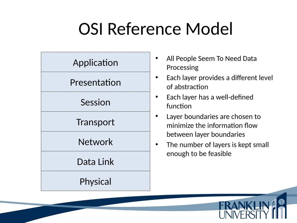
slide25. OSI Reference Model All People Seem To Need Data Processing
Each layer provides a different level of abstraction
Each layer has a well-defined function
Layer boundaries are chosen to minimize the information flow between layer boundaries
The number of layers is kept small enough to be feasible Physical Data Link Network Transport Session Presentation Application<br>
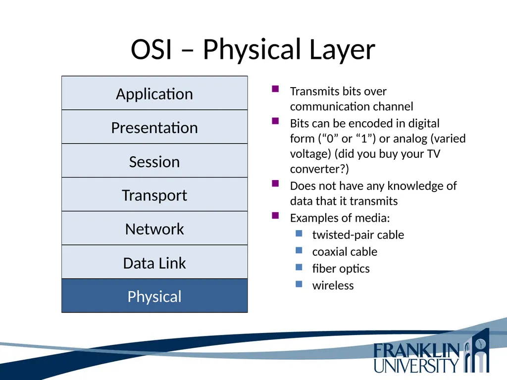
slide26. OSI – Physical Layer Transmits bits over communication channel
Bits can be encoded in digital form (“0” or “1”) or analog (varied voltage) (did you buy your TV converter?)
Does not have any knowledge of data that it transmits
Examples of media:
twisted-pair cable
coaxial cable
fiber optics
wireless Physical Data Link Network Transport Session Presentation Application<br>
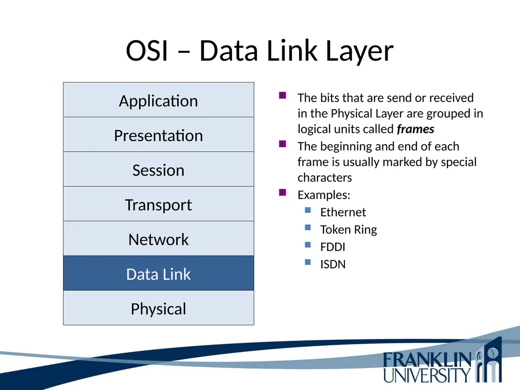
slide27. OSI – Data Link Layer The bits that are send or received in the Physical Layer are grouped in logical units called frames
The beginning and end of each frame is usually marked by special characters
Examples:
Ethernet
Token Ring
FDDI
ISDN Physical Data Link Network Transport Session Presentation Application<br>
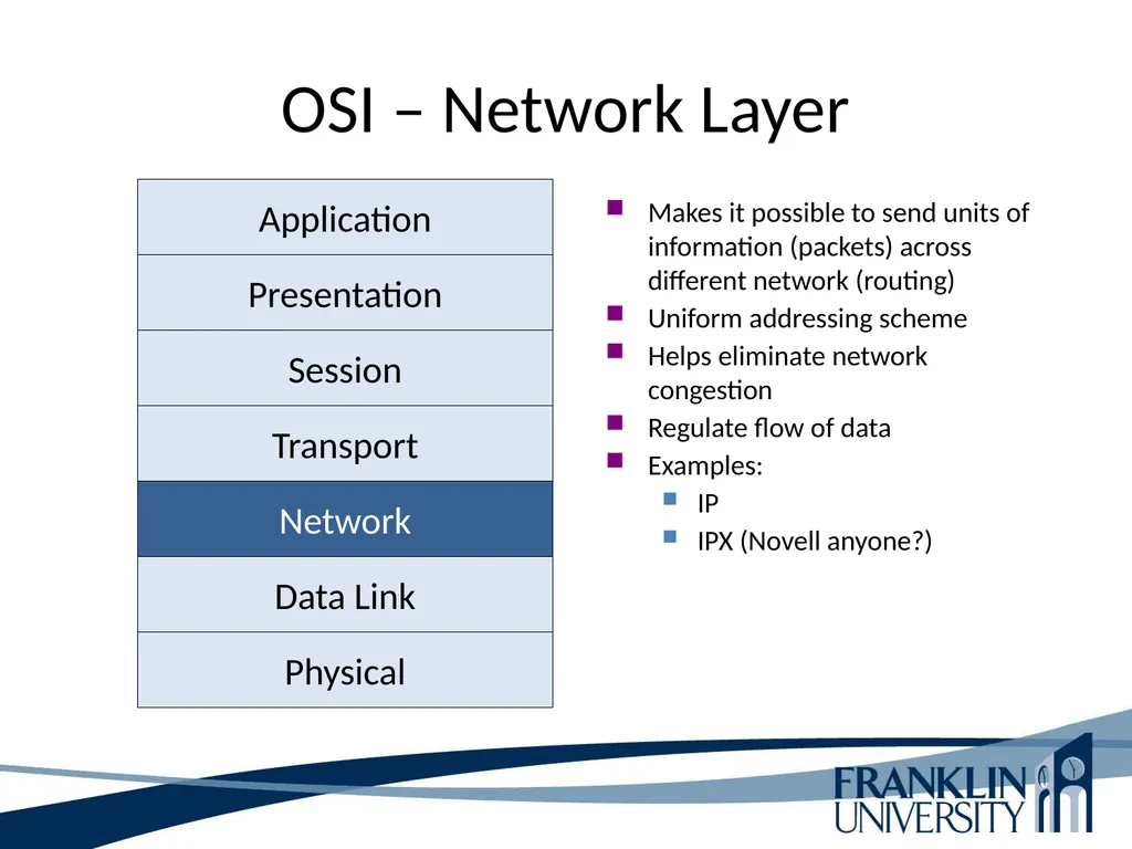
slide28. OSI – Network Layer Makes it possible to send units of information (packets) across different network (routing)
Uniform addressing scheme
Helps eliminate network congestion
Regulate flow of data
Examples:
IP
IPX (Novell anyone?) Physical Data Link Network Transport Session Presentation Application<br>
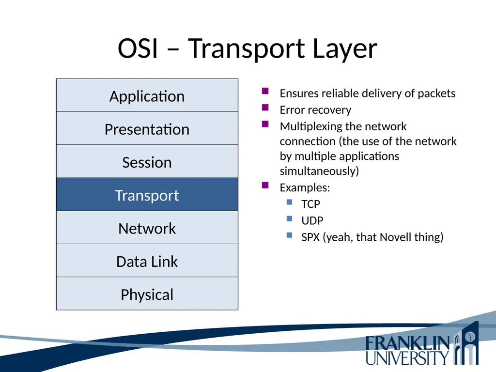
slide29. OSI – Transport Layer Ensures reliable delivery of packets
Error recovery
Multiplexing the network connection (the use of the network by multiple applications simultaneously)
Examples:
TCP
UDP
SPX (yeah, that Novell thing) Physical Data Link Network Transport Session Presentation Application<br>
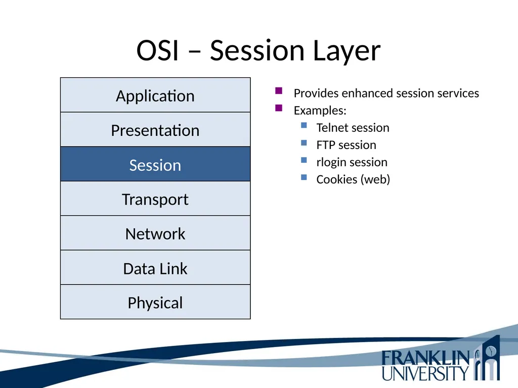
slide30. OSI – Session Layer Provides enhanced session services
Examples:
Telnet session
FTP session
rlogin session
Cookies (web) Physical Data Link Network Transport Session Presentation Application<br>
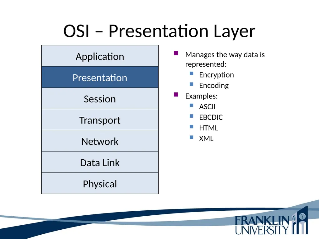
slide31. OSI – Presentation Layer Manages the way data is represented:
Encryption
Encoding
Examples:
ASCII
EBCDIC
HTML
XML Physical Data Link Network Transport Session Presentation Application<br>
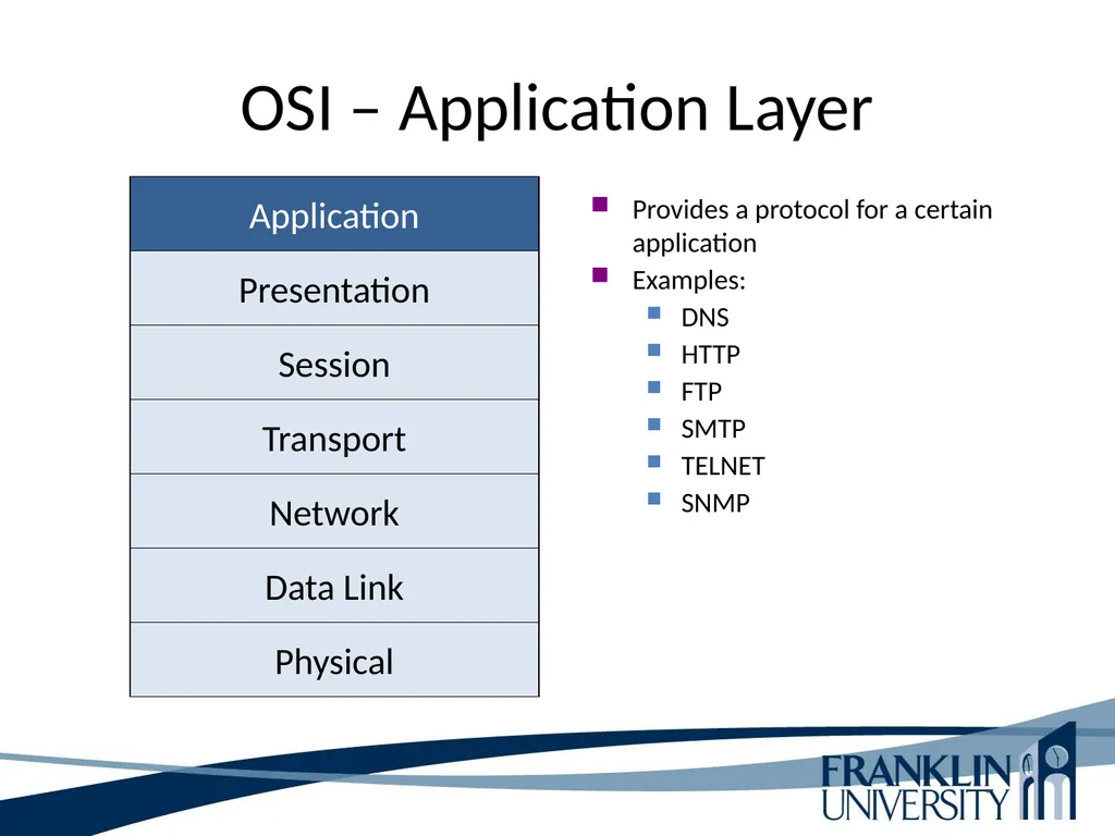
slide32. OSI – Application Layer Provides a protocol for a certain application
Examples:
DNS
HTTP
FTP
SMTP
TELNET
SNMP Physical Data Link Network Transport Session Presentation Application<br>
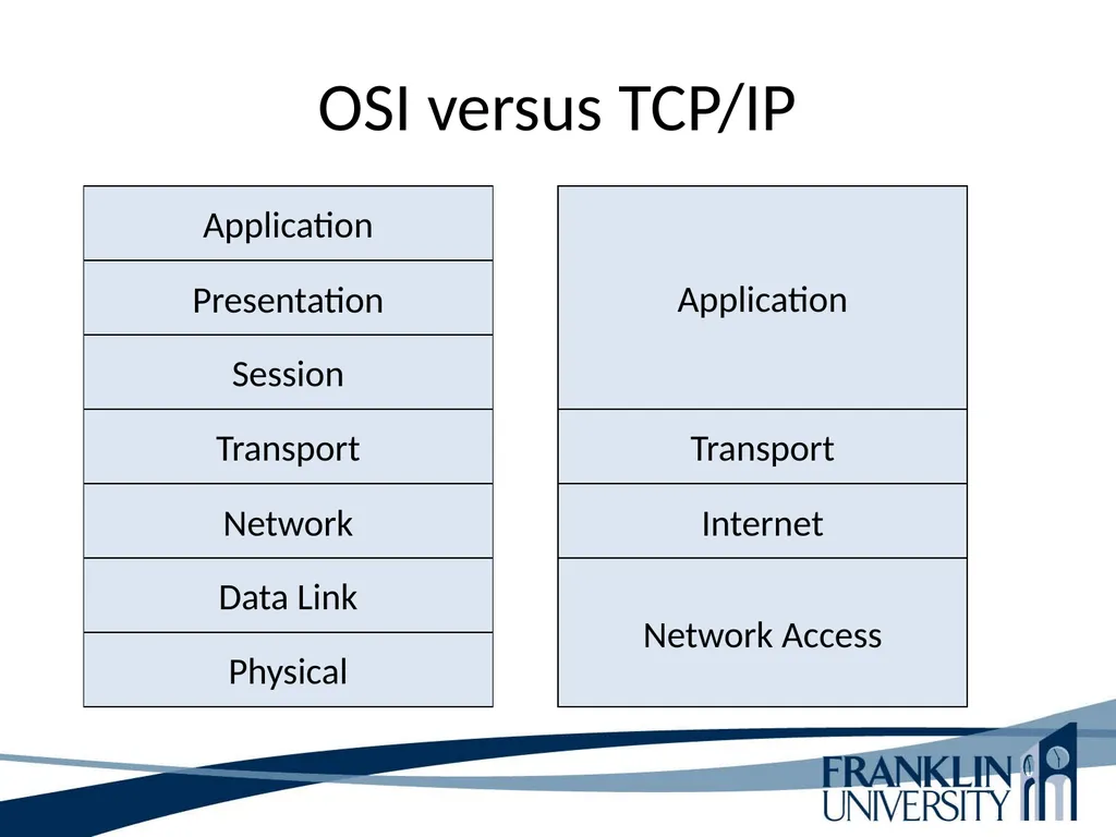
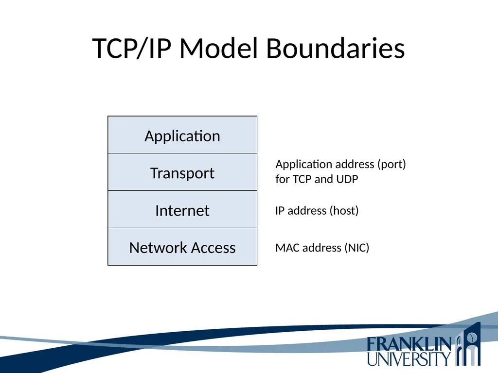
slide33. OSI versus TCP/IP Physical Data Link Network Transport Session Presentation Application Network Access Internet Transport Application<br>
slide34. TCP/IP Model Boundaries Network Access Internet Transport Application Application address (port)
for TCP and UDP MAC address (NIC) IP address (host)<br>
slide35. Protocol Data Unit (PDU) Contains information about the source and destination of a message. In the header. http://en.wikipedia.org/wiki/TCP/IP_model Figure 1-2<br>
slide36. Evaluate Business Constraints Company Politics
Throughout your discussion with the customer, try to learn who the individuals are that do the authorization, buying process, and fiscal period when buying occurs Be on the alert for:
Hidden agendas
Turf wars
Biases
Group relations
Individuals within the company that could cause the network project to fail (engineers or managers)
Number of employees affected by the new design
Customers preference towards the use of certain protocols,<br>
slide37. Evaluate Business Constraints Company Politics
Strategic business or IT plan
Customers preference towards the use of certain protocols
Forbidden technologies
Are the governmental guidelines that need to be followed
Determine the amount of risk the customer is willing to tolerate
Determine the group that controls the budget<br>
slide38. Evaluate Project Scheduling Review with Customer
Timeframe for project
Identify due date
Identify the implementation dates
What are the minor and major milestones<br>
slide39. Devices - Network Terminology Domain – A specific part of a network
Bandwidth – The amount of data that can be carried across a network in a given time period
Unicast data – Data meant for a specific device
Broadcast data – Data meant for all devices
Multicast data - Data that is meant for a specific group of devices
Bandwidth domain – All devices that share the same bandwidth (Collision domain)
Broadcast domain – All devices that receive each other’s broadcasts and multicasts<br>
slide40. Devices - Hubs Layer 1 device
Also known as repeaters
Connects multiple devices so that they are logically on one LAN
Has no intelligence
Sends data received on one port to all other ports
Devices connected receive all data other connections send
All devices are on one collision and broadcast domain<br>
slide41. Devices - Switches Layer 2 device
Segregates multiple devices into smaller LANs
Has some intelligence
Reads source and destination MAC addresses and sends data to the appropriate port based on that
All devices connected to one switch port are in the same collision domain
Devices connected to individual switch ports are in their own collision domain
All devices connected to a switch are in the same broadcast domain<br>
slide42. Devices – Multilayer Switches Does all that a layer 2 does but adds layer 3 and 4 capabilities
Acts as a router with some functions in hardware when used for VLAN functions
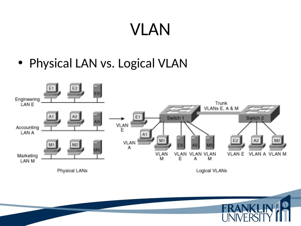
Groups ports into one or more VLANs that are configured (using management software) so that they can communicate as if they were attached to the same wire
VLANs are identified by different IP ranges
Trunk – A port that carries more than one VLAN between switches<br>
slide43. VLAN Physical LAN vs. Logical VLAN<br>
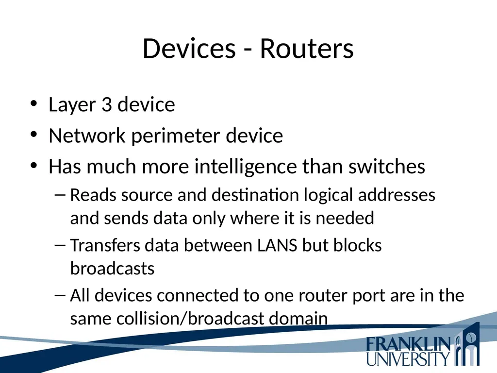
slide44. Devices - Routers Layer 3 device
Network perimeter device
Has much more intelligence than switches
Reads source and destination logical addresses and sends data only where it is needed
Transfers data between LANS but blocks broadcasts
All devices connected to one router port are in the same collision/broadcast domain<br>
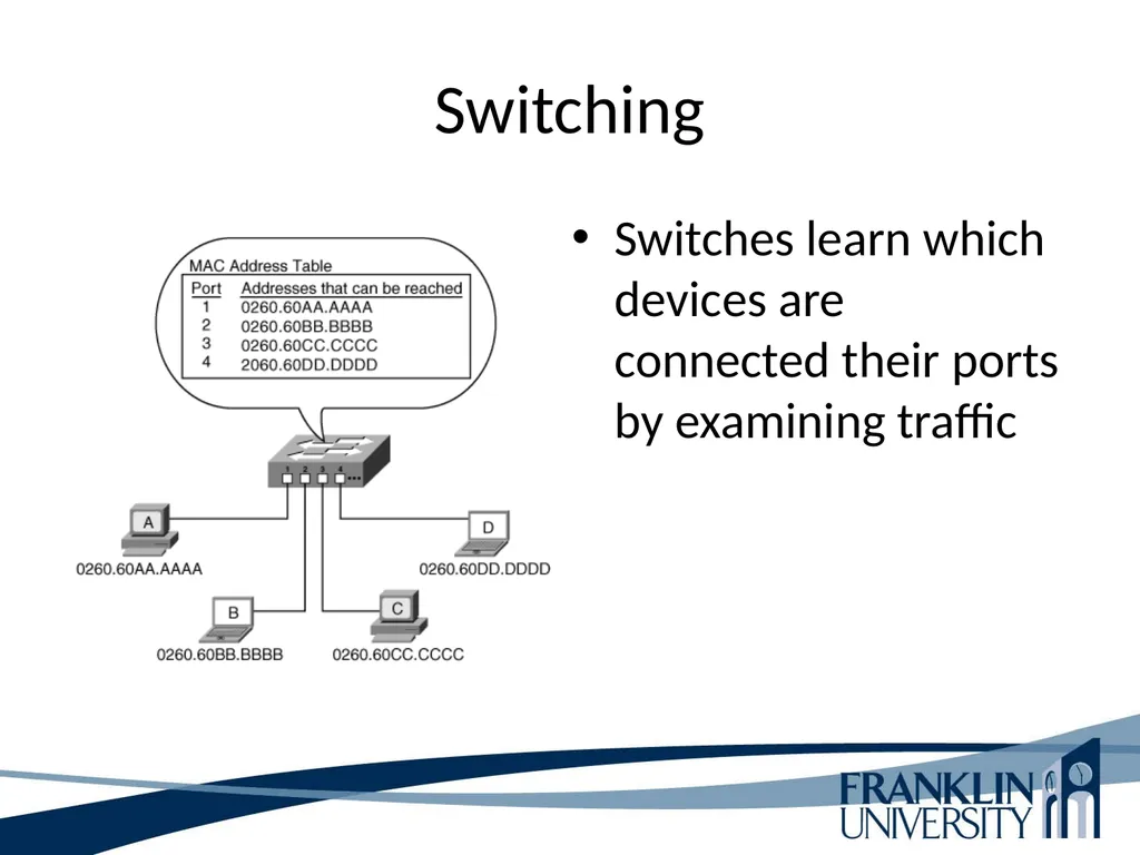
slide45. Switching Switches learn which devices are connected their ports by examining traffic<br>
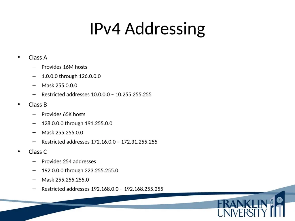
slide46. IPv4 Addressing Class A
Provides 16M hosts
1.0.0.0 through 126.0.0.0
Mask 255.0.0.0
Restricted addresses 10.0.0.0 – 10.255.255.255
Class B
Provides 65K hosts
128.0.0.0 through 191.255.0.0
Mask 255.255.0.0
Restricted addresses 172.16.0.0 – 172.31.255.255
Class C
Provides 254 addresses
192.0.0.0 through 223.255.255.0
Mask 255.255.255.0
Restricted addresses 192.168.0.0 – 192.168.255.255<br>
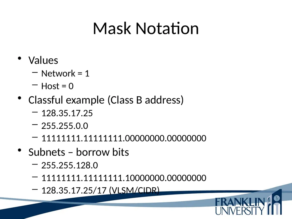
slide47. Mask Notation Values
Network = 1
Host = 0
Classful example (Class B address)
128.35.17.25
255.255.0.0
11111111.11111111.00000000.00000000
Subnets – borrow bits
255.255.128.0
11111111.11111111.10000000.00000000
128.35.17.25/17 (VLSM/CIDR)<br>
slide48. This Week’s Outcomes OSI Layers
Network Devices
Routing Protocols
Switching
Addressing<br>
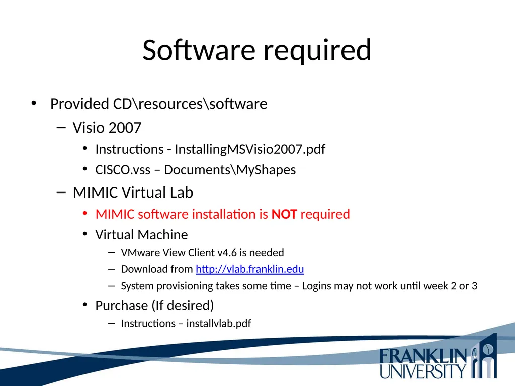
slide49. Software required Provided CD\resources\software
Visio 2007
Instructions - InstallingMSVisio2007.pdf
CISCO.vss – Documents\MyShapes
MIMIC Virtual Lab
MIMIC software installation is NOT required
Virtual Machine
VMware View Client v4.6 is needed
Download from http://vlab.franklin.edu
System provisioning takes some time – Logins may not work until week 2 or 3
Purchase (If desired)
Instructions – installvlab.pdf<br>
slide50. Due this week Software installation (no points)
Review course golas and objectives<br>
slide51. Next week Read chapters 1 and 2 in Top-Down Network Design
Obtain proctors for midterm and final exams
1-3 – Concept questions 1
FranklinLive session 2<br>
slide52. Q & A Questions, comments, concerns?<br>
slide2. Agenda Introductions
Review policies, procedures, and expected outcomes
Learning Activities
Introduce homework problems
Location of Power Point presentations
http://cs.franklin.edu/~dandrear/itec275/Fall_2013_Network_Presentations/Week_One_Network_ppt or .pptx<br>
slide3. Introductions Professor Robert D’Andrea
Adjunct faculty at Franklin
Teaching ITEC275 and ITEC 400
Cell phone 614.519.5853
Industry experience in security, systems administration, networking, software development, and deployment of software and hardware.<br>
slide4. Introductions Program Chair Information Technology Security
Professor Brad Reed
Brad.reed@franklin.edu
Cell phone 614.918.8321
Writing doctorate dissertation on Information Technology Security.<br>
slide5. Introductions Now your turn:
Name
Major
Interest level and experience in networking
Goal for this class<br>
slide6. Administration Principles of Computer Networks
Prerequisites: College Writing (COMM 120), and Principles of Computer Networks (COMP 204), or A Networking Fundamentals course.
This course serves as an introduction to the function, design, administration, and implementation of computer networks. Topics include network infrastructure, architecture, protocols, applications, and the OSI networking model.<br>
slide7. Administration Course Outcomes
Diagram an end-to-end network communication path, describing each intermediate step.
Design a small-scale network configuration, including addressing, routing, and switching.
Describe the functions of the TCP/IP and Ethernet protocols including select fields, flags, options, headers, and trailers for both.<br>
slide8. Administration Course Outcomes (ctd)
Distinguish between types of data elements (segments, packets, frames, and bits).
Map the key elements of the TCP/IP protocol suite to the OSI model.<br>
slide9. Administration Text
Oppenheimer, P. (2011). Top-Down Network Design: A systems analysis approach to enterprise network design. (3rd ed.). Indianapolis, IN: Cisco Press. ISBN: 978-1-58720-283-4.<br>
slide10. Administration Academic integrity
Items on the Web can serve as “inspiration” for your solutions if:
You understand the solution as if you had written it yourself.
You cite your source of inspiration
Not citing your source can get you charged with cheating/plagiarism.<br>
slide11. Administration Academic integrity
Items on the Web can serve as “inspiration” for your solutions if:
You understand the solution as if you had written it yourself.
You cite your source of inspiration
Not citing your source can get you charged with cheating/plagiarism. Note: if a homework problem says “research X,” or “investigate Y,” then I’m expecting a citation! Technically, you should cite your textbook on almost every HW assignment.<br>
slide12. Administration Academic integrity
Other students cannot serve as a source for your “inspiration!"
The closer you move toward sharing answers with or soliciting answers from another person (student or not), the more likely it is that you are cheating.<br>
slide13. Administration Academic integrity
If you have a vague feeling that you wouldn’t want your instructor to know about what you’re doing… don’t do it.
When in doubt, ask your instructor.<br>
slide14. Administration Points breakdown<br>
slide15. Daily/weekly Activities Daily: Check announcements and e-mail lists
Before class
Read the associated sections from the text books and key points
Read and consider the weekly homework problems
After class
Complete the homework assignment
Work on any scheduled lab assignments
Note significant learning<br>
slide16. Course Outcomes Upon successful completion of this course students will be able to:
Determine an appropriate approach to design a network based on customer needs and consideration of financial and technological constraints.
Identify the design considerations and tradeoffs for campus, WAN, and data center infrastructure models.
Select appropriate WAN components used in a standard WAN architecture.
Compare and contrast routing and addressing schemas and the mechanisms for implementing each one.
Identify and describe the components and standards used for implementing telephony into a data network.
Configure routers and switches using Cisco IOS commands.
Effectively communicate how a network design plan meets a customer's connectivity needs.<br>
slide17. COMP 204 Map protocols and addressing, routing, and switching into the appropriate layer of the OSI model.
Identify the main characteristics of hubs, switches, and routers.
Outline the features of the following TCP/IP protocols: UDP, TCP, IP.
Explain the characteristics of virtual LANs (VLANs) and Spanning Tree Protocol (STP) and the advantages they provide.<br>
slide18. Top-Down Network Design Analyze your customers business goals
Business goals are the capability to run network applications to meet an organizations business objectives, within the business constraints. These constraints could be limited network personnel, budgets, and limited timeframe.
Good network design subscribes to the customers requirements to the letter. This would include business and technical goals, requirements for availability, scalability, affordability, manageability, and security needs. Some customers will specify a required level of network performance, referred to as service level.
When a customer wants a quick fix design, it is referred to as a bottom-up network design. Associated with this type of design is unexpected scalability, poor performance, and does not meet the customers most important needs.
Top-down network design is a methodology for designing networks at the upper layers of the OSI model before referring to lower layers (devices, cabling, and switch configurations).
Top-down network design includes exploring organizational and group structures to find individuals the network is being designed to provide a services and from whom the design should get valuable information to make the design a success.<br>
slide19. Top-Down Network Design Top-down network design is iterative. Initially, it is important to get the overall view of the customers requirements. Later, after digesting the high abstractions of the design, then focus on the finer details of the design like protocol behavior, scalability requirements, and technology preferences. Top-down network design recognizes that the logical model and the physical design can change as more information becomes available.
A top-down network design approach enables the designer to obtain “the big picture” initially, and the drilling down for specifics requirements and technical details.
Top-down network design is a methodology the grew out of structured software programming and structured systems analysis.
Top-down network design divides the project up into small logical pieces known as modules. These modules allow large projects to be more manageable and easier to debug.<br>
slide20. Top-Down Network Design Modules are split into logical functions.
A top-down network design approach is divided into four major phases and are carried out in a cyclical fashion:
Analyze requirements - interview users and technical personal to gain an understanding of their business and technical goals for new or existing networks.
Develop the logical design – logical topology for the new or existing network, security, switching, routing protocols.
Develop the physical design – This phase addresses the specific technologies and products that are realized in the logical design are selected.
Test, optimize, and document the design – update the documentation that represents the network design, create test scenario, build a prototype or pilot network, optimize the network design.
The major phases of the top-down network design repeats itself. The user and the network monitoring suggest enhancements or the need for new specifications.<br>
slide21. Top-Down Network Design Network Design Plan Life Cycle
Plan – Identify the network requirements in this phase.
Design – Complete the bulk of the logical and physical design.
Implement – Implement the building of the proposed network design.
Operate – Final test the effectiveness of the network design. This includes monitoring the network and services.
Optimize – This phase is based on actual operations. Identifying and resolving problems that were encountered.
Retire – When part or the whole network design no longer meets the needs of the company and users, this should be an avenue of consideration. This component is not officially part of the life cycle model.
Plan Design Implement Operate Optimize (PDIOO) Network Life Cycle.<br>
slide22. Top-Down Network Design Network Design Components
Analyzing Business Goals – knowing your customers business goals and constraints. With a thorough understanding of your customers business objectives, you will be able to provide a network design that will meet your customers approval.
Working with Your Client – Research the type of business your client is in before meeting with them. Learn all that you can about his or her market, suppliers, services, and competitive advantage.
Changes in Enterprise Network – Internal users is limited for todays network needs. Your customer now has to think about remote entries both domestically, mobile access, RFS, and globally. Security is a topic that cannot be underestimated in our current network environment.
Network Must Make Sense – Business leaders today are more involved with IT decisions than past administrations. Customers want to operate leaner in data center personnel, power usage, and technology for technology’s sake.,<br>
slide23. Top-Down Network Design Network Design Components
Networks Offer a service – IT departments are more service oriented than they use to be in the past.
Governance refers to a focus on consistent, cohesive, policies, and processes that protect an organization from mismanagement and illegal operations of users of IT services.
Compliance refers to adherence to regulations that protect against fraud and the disclosure of private customer data.
Need to Support Mobile Users – Network users expect network performance to be uniform , regardless of where the user or data resides.
The Importance of Network Security and Resiliency – Enterprises have to protect themselves from internal, web, and external from more areas than past environments.
Typical Network Design Business Goals – listed on pages 13 and 14.<br>
slide24. Top-Down Network Design Identify the scope of the network design project.
Small in scope – sales staff might be allowed to access the enterprise network via VPN
Large in scope – engineering personal and remote access through the Enterprise Edge
Network designers should ask their customers to help them understand the scope of the network design project.
Network design questions:
1. Is the design for a single segment
2. A set of LANs
3. A set of WANs
4. Remote-access networks
5. Entire enterprise network<br>
slide25. OSI Reference Model All People Seem To Need Data Processing
Each layer provides a different level of abstraction
Each layer has a well-defined function
Layer boundaries are chosen to minimize the information flow between layer boundaries
The number of layers is kept small enough to be feasible Physical Data Link Network Transport Session Presentation Application<br>
slide26. OSI – Physical Layer Transmits bits over communication channel
Bits can be encoded in digital form (“0” or “1”) or analog (varied voltage) (did you buy your TV converter?)
Does not have any knowledge of data that it transmits
Examples of media:
twisted-pair cable
coaxial cable
fiber optics
wireless Physical Data Link Network Transport Session Presentation Application<br>
slide27. OSI – Data Link Layer The bits that are send or received in the Physical Layer are grouped in logical units called frames
The beginning and end of each frame is usually marked by special characters
Examples:
Ethernet
Token Ring
FDDI
ISDN Physical Data Link Network Transport Session Presentation Application<br>
slide28. OSI – Network Layer Makes it possible to send units of information (packets) across different network (routing)
Uniform addressing scheme
Helps eliminate network congestion
Regulate flow of data
Examples:
IP
IPX (Novell anyone?) Physical Data Link Network Transport Session Presentation Application<br>
slide29. OSI – Transport Layer Ensures reliable delivery of packets
Error recovery
Multiplexing the network connection (the use of the network by multiple applications simultaneously)
Examples:
TCP
UDP
SPX (yeah, that Novell thing) Physical Data Link Network Transport Session Presentation Application<br>
slide30. OSI – Session Layer Provides enhanced session services
Examples:
Telnet session
FTP session
rlogin session
Cookies (web) Physical Data Link Network Transport Session Presentation Application<br>
slide31. OSI – Presentation Layer Manages the way data is represented:
Encryption
Encoding
Examples:
ASCII
EBCDIC
HTML
XML Physical Data Link Network Transport Session Presentation Application<br>
slide32. OSI – Application Layer Provides a protocol for a certain application
Examples:
DNS
HTTP
FTP
SMTP
TELNET
SNMP Physical Data Link Network Transport Session Presentation Application<br>
slide33. OSI versus TCP/IP Physical Data Link Network Transport Session Presentation Application Network Access Internet Transport Application<br>
slide34. TCP/IP Model Boundaries Network Access Internet Transport Application Application address (port)
for TCP and UDP MAC address (NIC) IP address (host)<br>
slide35. Protocol Data Unit (PDU) Contains information about the source and destination of a message. In the header. http://en.wikipedia.org/wiki/TCP/IP_model Figure 1-2<br>
slide36. Evaluate Business Constraints Company Politics
Throughout your discussion with the customer, try to learn who the individuals are that do the authorization, buying process, and fiscal period when buying occurs Be on the alert for:
Hidden agendas
Turf wars
Biases
Group relations
Individuals within the company that could cause the network project to fail (engineers or managers)
Number of employees affected by the new design
Customers preference towards the use of certain protocols,<br>
slide37. Evaluate Business Constraints Company Politics
Strategic business or IT plan
Customers preference towards the use of certain protocols
Forbidden technologies
Are the governmental guidelines that need to be followed
Determine the amount of risk the customer is willing to tolerate
Determine the group that controls the budget<br>
slide38. Evaluate Project Scheduling Review with Customer
Timeframe for project
Identify due date
Identify the implementation dates
What are the minor and major milestones<br>
slide39. Devices - Network Terminology Domain – A specific part of a network
Bandwidth – The amount of data that can be carried across a network in a given time period
Unicast data – Data meant for a specific device
Broadcast data – Data meant for all devices
Multicast data - Data that is meant for a specific group of devices
Bandwidth domain – All devices that share the same bandwidth (Collision domain)
Broadcast domain – All devices that receive each other’s broadcasts and multicasts<br>
slide40. Devices - Hubs Layer 1 device
Also known as repeaters
Connects multiple devices so that they are logically on one LAN
Has no intelligence
Sends data received on one port to all other ports
Devices connected receive all data other connections send
All devices are on one collision and broadcast domain<br>
slide41. Devices - Switches Layer 2 device
Segregates multiple devices into smaller LANs
Has some intelligence
Reads source and destination MAC addresses and sends data to the appropriate port based on that
All devices connected to one switch port are in the same collision domain
Devices connected to individual switch ports are in their own collision domain
All devices connected to a switch are in the same broadcast domain<br>
slide42. Devices – Multilayer Switches Does all that a layer 2 does but adds layer 3 and 4 capabilities
Acts as a router with some functions in hardware when used for VLAN functions
Groups ports into one or more VLANs that are configured (using management software) so that they can communicate as if they were attached to the same wire
VLANs are identified by different IP ranges
Trunk – A port that carries more than one VLAN between switches<br>
slide43. VLAN Physical LAN vs. Logical VLAN<br>
slide44. Devices - Routers Layer 3 device
Network perimeter device
Has much more intelligence than switches
Reads source and destination logical addresses and sends data only where it is needed
Transfers data between LANS but blocks broadcasts
All devices connected to one router port are in the same collision/broadcast domain<br>
slide45. Switching Switches learn which devices are connected their ports by examining traffic<br>
slide46. IPv4 Addressing Class A
Provides 16M hosts
1.0.0.0 through 126.0.0.0
Mask 255.0.0.0
Restricted addresses 10.0.0.0 – 10.255.255.255
Class B
Provides 65K hosts
128.0.0.0 through 191.255.0.0
Mask 255.255.0.0
Restricted addresses 172.16.0.0 – 172.31.255.255
Class C
Provides 254 addresses
192.0.0.0 through 223.255.255.0
Mask 255.255.255.0
Restricted addresses 192.168.0.0 – 192.168.255.255<br>
slide47. Mask Notation Values
Network = 1
Host = 0
Classful example (Class B address)
128.35.17.25
255.255.0.0
11111111.11111111.00000000.00000000
Subnets – borrow bits
255.255.128.0
11111111.11111111.10000000.00000000
128.35.17.25/17 (VLSM/CIDR)<br>
slide48. This Week’s Outcomes OSI Layers
Network Devices
Routing Protocols
Switching
Addressing<br>
slide49. Software required Provided CD\resources\software
Visio 2007
Instructions - InstallingMSVisio2007.pdf
CISCO.vss – Documents\MyShapes
MIMIC Virtual Lab
MIMIC software installation is NOT required
Virtual Machine
VMware View Client v4.6 is needed
Download from http://vlab.franklin.edu
System provisioning takes some time – Logins may not work until week 2 or 3
Purchase (If desired)
Instructions – installvlab.pdf<br>
slide50. Due this week Software installation (no points)
Review course golas and objectives<br>
slide51. Next week Read chapters 1 and 2 in Top-Down Network Design
Obtain proctors for midterm and final exams
1-3 – Concept questions 1
FranklinLive session 2<br>
slide52. Q & A Questions, comments, concerns?<br>