
LESSON 1 FIRE AND SAFETY Critical Task:













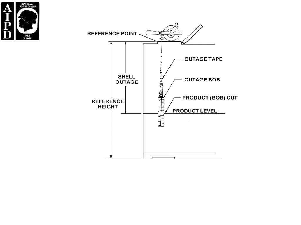

Description: LESSON 1 FIRE AND SAFETY Critical Task: 101-519-431 INTRODUCTION Because of the very nature of petroleum products, there are many hazards involved in the handling and storing of them. The greatest and most obvious is fire. However, we must
Related Topics
Download Presentation
"LESSON 1 FIRE AND SAFETY Critical Task:" is the property of its rightful owner. Permission is granted to download and print the materials on this website for personal, non-commercial use only, and to display it on your personal computer provided you do not modify the materials and that you retain all copyright notices contained in the materials. By downloading content from our website, you accept the terms of this agreement.
Presentation Transcript
slide2. LESSON 1
FIRE AND SAFETY
Critical Task:
101-519-431<br>
slide3. INTRODUCTION
Because of the very nature of petroleum products, there are many hazards involved in the handling and storing of
them. The greatest and most obvious is fire. However, we must not overlook the many health and safety hazards
in addition to fire that are also present in petroleum facility operations. As a senior NCO, you are responsible for
the fire prevention and safety program best suited to your petroleum facility. In addition you must ensure through
periodic training, drills, and inspections, that petroleum personnel in your area of responsibility are knowledgeable
of the fire and safety precautions and procedures discussed below.<br>
slide4. PART A – FIRE AND SAFETY TRAINING, INSPECTIONS, AND DRILLS
Your duties and responsibilities as a senior petroleum NCO often require you to ensure that procedures and
policies are being carried out. When dealing with petroleum, it is clear that fire and safety are probably the most
important considerations that you must make when developing general procedures and specific SOPs.
Fire and Safety Training. Fire and safety training begins when the soldier receives initial MOS
training and continues all the way through the soldier’s career. Given that the personnel in your unit will be in
almost constant contact with highly flammable products, fire and safety training will be an ongoing function.
Training should be incorporated into every function your unit performs. When developing an SOP, a periodic
training program should be incorporated into the procedures, ensuring that all personnel know and practice all
applicable fire and safety precautions and practices. Planned drills are an excellent way to enforce training
requirements and provide you as the senior NCO with an effective measurement tool that ensures personnel
training is sufficient.<br>
slide5. Inspections. Periodic planned and surprise inspections can also allow you to ensure that personnel are
following all applicable procedures related to fire prevention and safety. Most importantly , inspections can serve
to show you in what areas you may need to stress training, allowing you to develop a more complete training
program related to petroleum fire and safety. Some of the areas that you will need to establish inspection
procedures and intervals for are as follows:
Work area hazards.
Fire fighting and safety equipment.
Fire reporting and fighting procedures.
First-aid supplies and procedures.
Locations and availability of pertinent fire and safety information.
Fire and safety training records.
Fire and safety precautions and procedures during the performance of duties.<br>
slide6. PART B – NATURE AND CLASSES OF FIRES
Nature of fire.
Three elements are required to start and sustain a fire:
Heat (source of ignition) such as sparks, open flame, or static electricity.
Oxygen (air) which is always present.
Fuel (vapors) which in petroleum operations includes items such as MOGAS, diesel fuel, and JP4.
By ensuring that personnel know how to remove or prevent the presence of any one of these elements, a fire
can be easily prevented or extinguished.<br>
slide7. Classes of Fires.
There are four main classes of fire that you must ensure your personnel are familiar with. They are based on the
combustion characteristics of the material that is ignited:
Class A fire - These fires occur in combustible materials such as bedding, mattresses, books, cloth,
wood, and paper. The remains of these fires are charred embers.
Class B fire - These fires occur in flammable liquids such as gasoline, jet fuels, kerosene, oils, paints,
turpentine, grease, and tar.
Class C fire - These are electrical fires, and they can occur in wiring, electrical switches, and generators.
1-3 QM 5097
Class D fire - These involve combustible chemicals and metals such as sodium, potassium, titanium,
magnesium, zirconium, and phosphorous.<br>
slide8. PART C – CHARACTERISTICS AND SOURCES OF FIRE AND SAFETY
HAZARDS
Vapor Characteristics. In a fire, it is the vapor that actually burns. Characteristics of vapors
include:
Vapors are heavier than air and collect in low areas.
Vapors will hang low to the ground and spread over large areas.
On hot humid days vapors are produced in greater volume.
When vapors are allowed to collect, flashbacks can occur as the vapors come in contact with a heat
source and the heat travels back to the source of the vapors, causing a fire and possibly an explosion.
A 1- to 8-percent ratio by volume of vapors when mixed with air, will form an explosive range. An
explosive range is that point where the vapor and the air mixture will burn. A mixture above 8 percent is
too rich in vapors and will not ignite. A mixture below 1 percent is too lean in vapors (too rich in air) and
will not ignite.<br>
slide9. Control of Vapors.
Empty containers (5 gallon, 55 gallon) that have previously contained petroleum product are more
dangerous than full ones. Fill such containers as soon as possible, or when they are stored empty,
ensure caps and bungs are on tight.
Store containers that have fuel in them or containers that previously contained product in a safe area.
Do not overfill or fill containers at too fast a rate as vapors will be displaced to the atmosphere and
become a hazard.
Repair leaking pipes and containers as soon as possible.
Clean up spills immediately (as long as the contamination is present, vapors are a hazard).<br>
slide10. Sources of Ignition. A source of ignition can be either a flame, spark, or other heat-generating
source. Some of the most common causes of heat are:
Smoking material (matches, lighters, and cigarettes).
Sparks (static electricity, moving fuel, moving equipment, welding and cutting).
Spontaneous combustion (oxidation and chemical reaction).<br>
slide11. As a minimum, you should post “No smoking within 50 feet” signs in critical areas of the facility and enforce
the rule. Other precautions should also be observed/practiced, such as:
Designate all smoking areas at least 100 feet away from refueling operations.
In very hazardous areas, collect smoking materials at the entrance to the facility and keep them in
separate airtight containers at the entrance to the facility.
Welding and grinding should only be done under controlled conditions (that is, fire department notified,
vapor freeing completed, or when product in a pipeline is moving).
Electrical equipment must be maintained in safe working condition (approved electrical fixtures), and
grounding and bonding procedures must be utilized to minimize static electricity and arcing.
Ensure dispensing and receiving equipment is bonded and grounded.
Bottom load whenever possible, as top loading generates static electricity and splashing while filling.
Ensure that all personnel involved in gaging activities are trained to always bond themselves before
gaging storage tanks and tank vehicles.
Before gaging and sampling, allow a minimum of 30 minutes for the static charge to dissipate from fuel
receipts.
Always ensure that all fire extinguishers are in place and are operational.<br>
slide12. PART D - TYPES OF FIRE EXTINGUISHERS AND INSPECTION
PROCEDURES
Types of Fire Extinguishers.
There are four types of fire extinguishers your personnel should be familiar with: water, carbon dioxide, dry
chemical, and Halon.
Water extinguishers (pumped or pressurized) - May be used for Class A fires. This type of extinguisher
is used to control the heat. DO NOT USE for electrical, combustible metal, or flammable liquid fires.
Carbon dioxide extinguishers - May be used on electrical, chemical, or petroleum fires (Class B, C, and
D). This type of extinguisher controls the fire by diluting the air, thus choking the fire.
Dry chemical extinguishers - May be used on Class B, C, and D fires. This type of extinguisher is used
to smother the fire.
Halon extinguishers - Are effective against Class A, B, and C fires. The Halon extinguisher works
chemically to stop the combustion process. The agent, discharged as a liquid becomes a gas when it
contacts the fire.<br>
slide13. Inspection Procedures.
You must ensure that fire extinguishers are inspected at least monthly for serviceability. Any fire extinguisher
found unserviceable or discharged should be taken to the fire station for repair or recharging. The areas on the
extinguisher to be checked are:
In the body, check for dents, cracks, and excessive rust.
In the hose, check for dry rot, cracks, and missing parts.
Ensure that the seal is intact.
Ensure that the pressure gauge is in the “green,” fully-charged position.<br>
slide14. PART E- PRINCIPLES OF EXTINGUISHING FIRES
There are three basic methods your personnel will use to control and/or extinguish a fire:
Control the heat - Cooling or reducing the temperature of the fire below the ignition point will remove the
source of heat and control the fire.
Control the air - By reducing or eliminating oxygen in the air, combustion will no longer be supported. Air
is diluted by reducing the percentage of oxygen to the point where it will no longer support combustion. If
all air is cut off at the surface of combustion, a fire is smothered.
Control the fuel - Removing the combustible material or shutting off the flow of fuel will control the fire<br>
slide15. General Procedures to Extinguish a Fire. As a petroleum manager you can use drills or
other testing methods to ensure that your personnel are aware of the sequence of steps to take when a fire is
discovered. The recommended sequence is as follows:
Sound the alarm.
Call the fire department.
Determine the class of fire (A, B, C, D).
Select the appropriate fire extinguisher.
Stand upwind so that the flames and smoke blow away from you.
Point the fire extinguisher nozzle at the base of the fire.
Move the nozzle from side to side until the fire is extinguished<br>
slide16. PART F - FIRE FIGHTING TOOLS, CLOTHING, AND SAFETY TECHNIQUES
Tools. There are several types of tools used to fight ground cover fires. As a senior petroleum NCO, you should
ensure that the following items are on hand and in serviceable condition for all petroleum operations:
Rakes - Rakes are used to rake ground cover and dirt and to chop light growth. The types of rakes used
are as follows:
McLeod.
Council.
1-5 QM 5097
Rich Tool.
Fire Swatters - The fire swatter, or flapper, is used to beat the flames out. It may be effective on small
fires, but it could cause a fire to spread due to flying embers.<br>
slide17. Clothing. When faced with fighting a brush fire, nothing is more important to success than having the proper
equipment. An integral part of fire fighting equipment is clothing. It is your responsibility to ensure that there is
adequate clothing on hand for any type of fire fighting situation that may arise. The type of clothing required varies
in relation to your mission and the type of fires that may occur. When planning operations, as well as ensuring
base-unit readiness, you must always consider the availability of the proper fire fighting clothing.<br>
slide18. Safety Techniques. As a senior NCO, you should ensure that personnel are thoroughly familiar with the
following techniques for fighting a ground cover fire:
Always know the current escape routes.
Safety may be gained by moving into the burned area (as a last resort only).
Always work a fire on a slope from below.
Always work downwind of a fast-moving fire.
Use caution in felling or cutting trees.
Pace yourself; ground cover fires usually require long periods of hard work.
Stay with your crew.
When working on the fire line, stay 10-15 feet from the nearest co-worker.
Post a lookout to watch for a change in the fire’s behavior.
Work as a crew; this is not a contest to see who can cut the most line.
If you find yourself surrounded by fire, dig a pit and cover yourself with dirt.<br>
slide19. PART G – GENERAL PETROLEUM HEALTH HAZARDS
Dusts. Dust results from the grinding, scraping, sanding, or sandblasting of tanks, especially in the case of
tanks that have held leaded fuels. Lead dust can also result from burning sludge taken from leaded gasoline
storage tanks. Lead, manganese, mercury, arsenic, and any compound made of these items can produce
dust that is poisonous to the body. Silica dust resulting from the operation of grinding and polishing machines
or sanding and sandblasting operations can be fibrous-producing, causing injury to the lungs. Nuisance dusts
may cause inflammation and respiratory ailments.<br>
slide20. Gases and Vapors. The terms "gas" and "vapor" are often used to mean the same thing, although there is
a difference. A gas exists as a gas at ordinary temperature and pressure. A vapor is a gas-like form of a
substance that is ordinarily a liquid. Gasses and vapors are divided into four groups. Poisonous or toxic
gasses and vapors have various effects on the body. They may injure or destroy the visceral organs, the
blood-forming system, tissues, or bones. Examples of poisonous gasses or vapors are hydrogen sulfide
found in crude oil of high sulfur content and tetraethyl lead vapor from leaded gasoline. You must avoid
exposure to them at all times. Simple asphyxiates are gasses and vapors that keep the lungs from getting air.
In other words, they replace oxygen that is in the air. Anesthetic gasses and vapors have a narcotic effect,
depressing the central nervous system to the point where respiratory failure may occur. All hydrocarbon
vapors have this effect. Irritant gasses and vapors inflame the lungs and respiratory tract. They may cause
pneumonia and other pulmonary diseases or make the victim more susceptible to them. Most flammable
gasses and vapors are irritants whether or not they are poisonous or narcotic.<br>
slide21. PART H - FIRST AID FOR SITUATIONS INVOLVING PETROLEUM
PRODUCTS
When personnel swallow petroleum products, assisting personnel should:
Keep the victim calm, if possible.
DO NOT INDUCE VOMITING.
Get the victim to medical help immediately.
In the eyes:
Flush the eyes for several minutes with clean water to try to remove the product.
Cover the eyes for several minutes with a sterilized dressing, and prevent the victim from rubbing the
eyes.
Seek medical help immediately.
On the clothing:
Remove the clothing after soaking the fuel-soaked clothing first with water. (This should prevent
sparking.)
Wash with soap and water and rinse thoroughly.
Get to medical help, if needed<br>
slide22. PART I - ACCIDENT REPORTS
Accident reporting is a very important aspect of a fire and safety program. Accident reports allow all personnel,
from the front line supervisor to senior doctrinal planners, to track and quantify safety-related trends that may lead
to changes or revisions in Army or even DOD policy related to doctrine and general procedures. By ensuring the
proper completion of accident reports, you, as a supervisor, are providing useful data that may be used to effect
changes in unsafe procedures and practices that in turn will save lives in the future and provide for a more efficient
and effective Army. Instructions for the use and procedures for properly completing DA Form 285 can be found in
AR 385-40.<br>
slide23. PART J - PETROLEUM FIRE PREVENTION AND SAFETY SOP
All of the information provided in this lesson would be useless if it were not documented and used to establish a
standard set of daily operating procedures that can be incorporated into your personnel’s everyday tasks. As the
senior NCO of your unit , you are responsible for developing a petroleum supply fire and safety SOP. The format
for most SOPs is standard and is provided in Appendix B of FM 10-426 (Petroleum Supply Units). Below is an
extract from FM 10-426, Appendix B. This format is designed to ensure a standard and complete set of
procedures related to the particular SOP being developed. It is important to realize that while this format dictates
the sequence and content requirements for an effective SOP, you must also include procedures that are peculiar
to your unit and overall mission<br>
slide24. Unit Location - Using unit location.
References - Applicable references used to develop SOP.
Required - SOP content.
Purpose - Tell the reason you are establishing the SOP.
Scope - Specify procedures and requirements to be covered by the SOP.
Responsibility - Responsible personnel for each set of procedures.
Procedures - State which operating procedures are to be used and intervals when applicable.
Miscellaneous - Any additional pertinent information to be included.
Definition Section - Definitions of terms.
Signs and Symbols - Explanation of symbols and/or signs used.
Special Instructions<br>
slide25. LESSON 2
PETROLEUM SUPPLY IN A THEATER OF OPERATIONS<br>
slide26. INTRODUCTION
In any major conflict, the anticipated tonnage associated with bulk petroleum products will account for over 50
percent of the total tonnage shipped into a theater of operations. The petroleum distribution system must be
flexible enough to meet the changing priorities of a fluid battlefield and reallocate resources as necessary.
Adjustments must be made to meet variations in intensity of warfare. As a petroleum NCO, understanding the
petroleum distribution system will assist you in planning for support<br>
slide27. PART A - DISTRIBUTING FUEL IN A THEATER OF OPERATIONS
The flow of fuel requirements begins with the submission of fuel forecasts from consuming units. Forecasted
fuel is then distributed as far forward as possible to satisfy the most forward needs first and then and only then
is any fuel placed in storage.
The using unit submits their forecast through the S4 channels to the Division Material Management Center
(DMMC). The DMMC prepares the division forecast from the main support battalion (MSB), forward support
battalion (FSB), and Aviation Brigade (AVN BDE) units logistics reports and forwards the requirements to the
Corps Material Management Center (CMMC).
The CMMC consolidates all the requirements from other divisional and nondivisional commands within the
corps area and forwards the entire corps forecast to the Theater Materiel Management Center (TMMC).<br>
slide28. PART B - UNITS RESPONSIBLE FOR DISTRIBUTION
Communications Zone. The communications zone (COMMZ) is the rear part of the theater of
operations and contains the lines of communication establishment for supply and evacuation and other
agencies required for the immediate support and maintenance of the field forces. The Joint Petroleum Office
(JPO) consolidates theater petroleum requirements for all services. prepares the “slate” (request for delivery
of fuel byproduct, quantity, and location), and forwards it to the Defense Energy Support Center (DESC). The
Petroleum Group operates the bulk petroleum distribution system extending from ports of entry through the
COMMZ and as far into the combat zone as practicable<br>
slide29. Combat Zone. The combat zone is the area required by combat forces for the conduct of operation. This
area is the territory forward of the Army rear area boundary.
Corps Area. The Corps Support Command (COSCOM), located in the corps area, provides combat service
support to Army forces in the corps area, direct support (DS) and general support (GS) to nondivisional units,
and GS to divisional units.
Petroleum Supply Battalion. Provides DS and GS petroleum in the corps and divisional areas.
Petroleum Supply Company. Receives, stores, and issues bulk petroleum to divisional and nondivisional
DS companies on a 24-hour basis. Receives fuel from the petroleum pipeline and terminal operating
company. Issues fuel to divisional and nondivisional DS supply and services companies and aviation
brigade and/or battalions. The capabilities and/or responsibilities of this organization are:
Install, operate, and retrieve approximately 10 miles of collapsible hoseline per day.
Maintain prescribed reserve stock supply.
Provide limited mobile filling station service.
Operate two to four supply points at different locations. Storage capacity includes twenty-eight
10,000-gallon collapsible tanks and twenty-four 50,000-gallon collapsible tanks for a total of
1,480,000-gallon capacity.<br>
slide30. Medium Truck Company (Petroleum). Provides transportation for bulk petroleum between GS and DS
petroleum organizations. The capabilities and/or responsibilities of this organization are:
Assigned sixty 5,000-gallon tanker trucks.
Can line haul 450,000 gallons of fuel each day. This is based on an assumption of 75 percent vehicle
availability and two round-trips completed each day.
Can local haul 900,000 gallons of fuel each day. This is based on an assumption of 75 percent
vehicle availability and four round-trips completed each day.
Has storage capacity of 300,000 gallons in the 5,000-gallon tanker trucks.
COSCOM Support Group. Provide area supply and services to units passing through or located in its
assigned corps areas.<br>
slide31. Supply and Services Battalion. Provides supplies and field services on a DS basis to nondivisional units
passing through or located in the corps area.
Supply and Services (S&S) Company DS. Provides direct support petroleum supply to nondivisional units
located in or passing through the corps area. Receives fuel from the Petroleum Supply Company. The
capabilities and/or responsibilities of the organization are:
Storage capacity of 120,000 gallons in two Fuel System Supply Points (FSSPs).
Assigned nine 5,000-gallon tankers.
Can line haul 81,900 gallons of fuel each day. This is based on an assumption of 75 percent vehicle
availability and two round trips completed each day.
Operate mobile filling stations when required<br>
slide32. Divisional Area. The Division Support Command (DISCOM), located in the divisional area, provides divisionlevel
combat service support (except COMSEC logistics, construction, financial services, legal services, and
public affairs) to all organic and attached elements of the division. Subordinate elements of the DISCOM are
the Main Support Battalion (MSB) and three Forward Support Battalions (FSBs).
MSB. Provides division-level combat service support to all organic and attached elements of the division.
The MSB provides direct support to units located in the Division Support Area (DSA) and backup to the
FSB.
Supply and Services (S&S) Company DS. Provides division-level supply and services to all organic and
attached elements of the division. The S&S Company provides direct support to units located in the DSA
and backup to the FSB’s Supply Company. Receives fuel from Petroleum Supply Company. The
capabilities and/or responsibilities of this organization are:<br>
slide33. Storage capacity of 304,000 gallons in two Fuel System Supply Points (FSSPs), two Forward Area
Refueling Equipment (FARE) systems, thirty-four 5,000-gallon tanker trucks, and two tank and pump
units (TPUs).
Can line haul 258,600 gallons of fuel each day. This is based on an assumption of 75 percent vehicle
availability and two round-trips completed each day.
Can local haul 517,200 gallons of fuel each day. This is based on an assumption of 75 percent
vehicle availability and four round-trips completed each day.
By doctrine, can handle only ground fuel (MOGAS and diesel).<br>
slide34. Forward Support Battalion (FSB). Provides brigade-level combat service support to all organic and
attached elements of the brigade.
Supply Company. Provides brigade-level petroleum to all organic and attached elements of the brigade.
Receives fuel from the Petroleum Supply Company and backup from the MSB AMS Company. The
capabilities and/or responsibilities of this organization are:
Storage capacity of 53,600 gallons in ten 5,000-gallon tanker trucks and two tank and pump units.
Can line haul 78,600 gallons of fuel each day. This is based on an assumption of 75 percent vehicle
availability and two round-trips completed each day.
Can local haul 157,200 gallons of fuel each day. This is based on an assumption of 75 percent
vehicle availability and four round-trips completed each day.
By doctrine, handles only ground fuels (MOGAS and diesel) and single fuels on the battlefield
(JP8/MOGAS).<br>
slide35. Combat Aviation Brigade (CAB). Provides DS petroleum to the units organic to the CAB. The CAB
receives fuel directly from the COSCOM by means of either hoselines or tanker trucks from the Petroleum
Supply Battalion. Capabilities - The CAB provides petroleum to its subordinate units using either the air
transportable 500-gallon collapsible drums, heavy expanded mobility tactical trucks (HEMTTs) or the tank
and pump units. The CAB will normally form forward area refueling points in the division forward area to
minimize the time required to replenish the aviation logistics necessary to continue combat operations.
Light Division, Division Support Command (DISCOM). In the light divisions, the DISCOM fulfills its
petroleum DS mission through its organic Supply and Transportation (S&T) Battalion. The S&T Battalion
establishes refuel points in the DSA and forwards in the BSA to provide fuel on an area basis. It will use
the organic truck company to refuel the refueling points via the 5,000-gallon tankers organic to the
company<br>
slide36. LESSON 3
DETERMINE PETROLEUM REQUIREMENTS<br>
slide37. INTRODUCTION
One of the most important functions of a petroleum manager is the adequate forecasting of petroleum
requirements. Without an accurate forecast of requirements, the orderly flow of petroleum products is
threatened. There are five methods for computing petroleum requirements. They are listed in order from best
to worst: historical data method, combat profile, fuel consumption unit (STANAG 2115), equipment
consumption, and gallons per person per day.<br>
slide38. PART A - HISTORICAL DATA METHOD
The historical data method is the best method and considers the following factors: same vehicles, same
distances, and similar resupply source, weather, and terrain. Record keeping for actual consumption during
major training exercises and tactical marches is essential for correct calculations using this method.<br>
slide39. PART B - COMBAT PROFILE
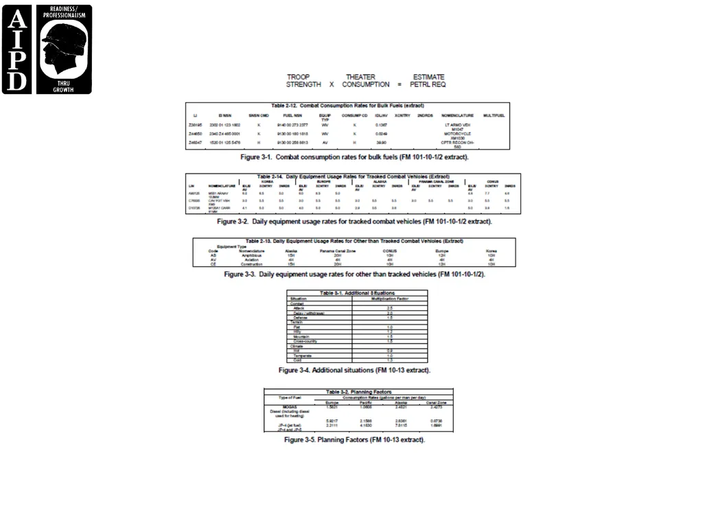
The combat profile method tracks combat vehicles only. You must use FM 101-10-1/2, Table 2-12, Combat
Consumption Rates for Bulk Fuels (Figure 3-1) to obtain consumption rates (factors) and Table 2-14, Daily
Equipment Usage Rates for Tracked Combat Vehicles (Figure 3-2). Add together subtotals (shown below)
and multiply by number of vehicles to get the total fuel requirement.
CONSUMPTION USAGE
FACTOR RATES SUBTOTAL
IDLE X =
CROSS COUNTRY X =
SECONDARY ROADS X =<br>
slide40. PART C - FUEL CONSUMPTION OF UNIT
The NATO STANAG 2115 method is a standard used by NATO in determining fuel consumption. The fuel
consumption unit (FCU) considers combat, terrain, and climate. You must use tables found in FM 101-10-1/2,
Table 2-12, Combat Consumption Rates for Bulk Fuels (Figure 3-1) (excerpt provided) to obtain consumption
rates (factors), Table 2-13, Daily Equipment Usage Rates for Other than Tracked Combat Vehicles (Figure 3-
3), and FM 10-13, Table 3-1, Additional Situations (Figure 3-4), (excerpt provided)..
COMBAT QUANTITY USAGE
CONSUMPTION X OF X RATE = TOTAL GALLONS
RATE EQUIPMENT
TOTAL COMBAT TERRAIN CLIMATE
GALLONS X FACTOR X FACTOR X FACTOR = FCU<br>
slide41. PART D - EQUIPMENT CONSUMPTION
When using the equipment consumption method, you must know what equipment is to be used (TOE, TDA, or
equipment listing) and must use FM 101-10-1/2, Tables 2-12, Combat Consumption Rates for Bulk Fuels
(Figure 3-1, excerpt provided) to obtain consumption rates (factors), Table 2-13, Daily Equipment Usage
Rates for Other than Tracked Combat Vehicles (Figure 3-3, excerpt provided), and Table 2-14, Daily
Equipment Usage Rates for Tracked Combat Vehicles (Figure 3-2, excerpt provided). This method may be
used at all levels. Here is an example:
Combat Quantity Area Bulk
Consumption X Equipment X Usage = Fuel Rate
Rate Requirement<br>
slide42. PART E - GALLONS PER PERSON PER DAY
3-3 QM 5097
The least desirable or accurate method is the gallons per person per day method and it is primarily used for
early planning stages and for funding. You must use FM 101-10-1/1, and FM 10-13, Table 3-2, Planning
Factors (Figure 3-5), types of fuel to be used, and geographic consumption rates.
TROOP THEATER ESTIMATE
STRENGTH X CONSUMPTION = PETRL RE<br>
slide44. LESSON 4
PREPARE ACCOUNTING SUMMARIES<br>
slide45. INTRODUCTION
Until bulk petroleum products are consumed, they must be handled many times. Accurate records for receipts,
storage, issue, and shipment of petroleum products must be maintained. As a petroleum manager, your duties
will require supervising and reviewing accountability procedures. Accountability is necessary in determining
the quantities of petroleum products on hand and for the verification of quantities received and issued<br>
slide46. PART A - PETROLEUM ACCOUNTABILITY
Procedures to properly manage, control, safeguard, and account for petroleum products must be pursued and
involve prompt and accurate identification of shortages and overages and taking action to identify causes for
deviation.
Organizations handling bulk fuels will establish, maintain, and provide an SOP to operating personnel for
handling and accounting for bulk fuel by the particular organization. Organizations will train petroleum
handling personnel to ensure that safe and proper procedures are followed. All storage tanks greater than
10,000 gallons will have a certified capacity table. A certification of capacity table for tanks of 10,000 gallons or
less is optional.<br>
slide47. The appointment of a seal custodian, responsible for the quality and quantity of inspected petroleum
products, is another responsibility of senior petroleum NCOs. This appointment must be accomplished in
writing and is recommended that this appointment be noted in the applicable petroleum supply SOPs.
As a senior NCO in a petroleum organization, you are responsible for establishing and maintaining a
viable SOP to be used by your organization for petroleum inventory, accountability, and pilferage control
operations. Using the format provided in FM 10-426, Appendix B, and the information contained in this
lesson, will give you an idea of the general coverage area required for this particular SOP. As with any SOP, it
is important to remember that that specific procedures will be developed and implemented based on your
unit’s specific operations and mission responsibilities<br>
slide48. PART B- PREPARING BULK PETROLEUM ACCOUNTABILITY DOCUMENTS
Soldiers storing or transferring Class III products must accurately account for receipt, issue, and stocks on hand
for both bulk and packaged products. The biggest challenge in accounting for Class III products (particularly bulk
products) is adequately measuring them. Descriptions and procedures for completing the forms mentioned above
can be found in DA PAM 710-2-1, Using Unit Supply System (Manual Procedures).
Petroleum accounting records include:<br>
slide49. Daily status report. Soldiers operating a Class III facility submit reports showing quantities of product
received, issued, and on hand.
DD Form 1348-1, DOD Single Line Item Release/Receipt Document. Soldiers receiving petroleum into a
Class III facility use this form to record the receipt.
DA Form 2765-1, Request for Issue or Turn-In. Customers use this form to request packaged and bulk
products or to turn in excess cans, drums, or supplies.
DA Form 3643, Daily Issues of Petroleum Products. This form is the basic accountability record for
receipts and issues at a supply point.
DA Form 3644, Monthly Abstract of Issues of Petroleum Products and Operating Supplies. Soldiers doing
accountability post summarized information from DA Form 3643 to this form to show total monthly issues
and receipts.
DA Form 4702-R, Monthly Bulk Petroleum Accounting Summary. Units use this form to report all losses
or gains revealed by monthly inventories.
DA Form 2064. Document Register for Supply Actions. Personnel operating Class III storage facilities
must establish a stock record card or property record for each type or grade of product. They use this
form to post accountable records<br>
slide50. DA Form 1296 (Stock Account Record) or DA Form 3-8 (Stock and Property Records) will be used to
keep day-by-day stock/property records that reflect where and how much of each product is on hand at a
storage facility.
4-3 QM 5097
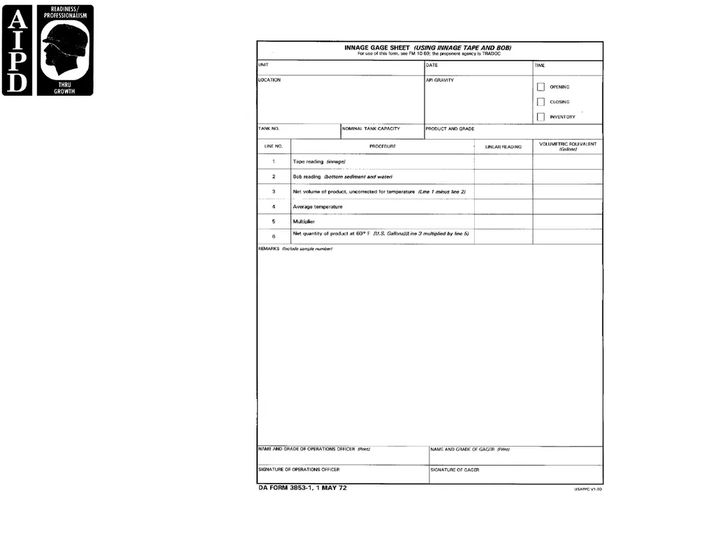
DA Form 3853-1, Innage Gage Sheet (Using Innage Tape and Bob). This form is used to record physical
inventories of bulk fue<br>
slide51. PART C - DETERMINING ALLOWABLE AND ACTUAL LOSSES
Some losses or gains are to be expected when handling and storing volatile products. Allowable loss and gain
percentages prescribed in the regulation are considered sufficient to accommodate expected normal product
losses and gains. Handling loss or gain of jet fuels, AVGAS, gasoline, and all other products are allowable up
to the extent of the actual loss or gain allowances. Losses or gains for jet fuels, AVGAS, and gasoline, must
not exceed 1 percent of the total of the opening inventory plus the receipts for the monthly period covered by
the Monthly Bulk Petroleum Accounting Summary (MBPAS). Losses or gains for all other petroleum products
must not exceed 1/2 of 1 percent of the total opening inventory, plus the receipt amount on the MBPAS<br>
slide52. In instances where the total loss of a specific bulk petroleum product may be less than the loss allowance
for that product, only the actual loss will be allowable.
For actual losses that exceed the stated allowance and the entire loss has a monetary value of $500 or
more, a report of survey is required.
Actual losses exceeding the allowable, but having a total monetary value less than $500 will require a
causative research to be initiated. A copy of either the report of survey or causative research will be
attached as supporting documentation to the MBPAS.<br>
slide53. PART D - ADJUSTMENT OF ACCOUNTABLE RECORDS
The DA Form 1296 for bulk petroleum products will be adjusted by using DA Form 4702-R (MBPAS) for all
losses and gains revealed by the monthly inventory. You must ensure that the accountable officer completes
the MBPAS, assigns it a voucher number, and posts it to the respective accountable records within 3 working
days of the last day of the month for the report.
The MBPAS is used to reflect the on-hand inventory and to make adjustments to the accountable stock
records<br>
slide54. Losses due to spillage or contamination will be documented by the accountable/responsible officer for
quantities over 25 gallons.
The documentation of loss will be attached to the MBPAS as a supporting document to adjust the
accountable records.
Adjustments to product inventories are required for blending, or regrading actions as follows:
The accountable/responsible officer will prepare a statement stating the quantities of all products
blended/regraded during the month and the reason for action.
The statement and a copy of the proper laboratory report are attached to the MBPAS as supporting
documents.
The MBPAS upon completion, will be forwarded to the approving authority, who may disapprove any item
on the MBPAS. If the approving authority disapproves an item, the initiation of a report of survey is
required.
The MBPAS with all supporting documents (receipts and issues) will be retained in an active file for 1 year
and in an inactive file for 2 years<br>
slide55. PART E - COMPUTING VOLUME CORRECTIONS
When monitoring accountability functions, you must ensure that personnel use the volume correction factor to
correct fuel volume observed at temperatures other than 60F. Do this after obtaining the API gravity reading
at 60 F and the average temperature of product in the tank.
Volume correction of quantities less than 3,500 gallons is optional.
Correct the volume of residual fuel (FO #4, FO #5, FO #6) regardless of measured quantity.
Volumes that equal or exceed 3,500 gallons must be corrected. Use the volume correction factors in
ASTM tables 5B and 6B for petroleum products other than JP4.
ASTM Tables 5A and 6A will be used for JP4.
Use ASTM Tables 52, 53B, and 54B to correct measured volumes to gallons at 15° Centigrade<br>
slide56. PART F – PILFERAGE CONTROL MEASURES
Casual Pilferage. The most practical and effective method for controlling casual pilferage is through the
use of psychological deterrents. One psychological deterrent is to search individuals and vehicles leaving the
installation at unannounced times and places. When conducting spot searches, care must be taken to ensure
that personnel are not demoralized nor their legal rights violated by oppressive physical controls or unethical
security practices. An aggressive security education program is also important. All employees must realize
that pilferage is morally wrong no matter how insignificant the value of the item taken. It is up to you to set a
proper example. All employees must be impressed with the fact that they have a responsibility to report any
loss to property authorities. Inventory and control measures such as identification of all tools and equipment
should be instituted to account for all material, supplies, and equipment. Do not lose sight of the fact though,
that most employees are honest and disapprove of thievery.<br>
slide57. Systematic Pilferage. Control measures must be taken to prevent systematic pilferage. In order to
ensure effective pilferage control throughout the facility you must first eliminate potential thieves during the
hiring procedure by careful screening and observation and by establishing customer identification. Inside the
facility, you must establish an effective key control system and an effective package and material control
system. It may be advisable to install mechanical and electrical devices including appropriate perimeter
fencing, lighting, and parking facilities and effective pedestrian, railway, and vehicle gate security controls in
order to establish security surveillance of all exits. The facility security can also be increased by establishing
adequate security patrols to check buildings, grounds, perimeter, and likely locations that may be used for
storage of pilfered items. Additionally, you may locate parking areas for private vehicles outside the perimeter
fencing of the activity. In the event of a loss, investigate quickly and efficiently.
In all cases, develop local SOPs according to security requirements and implement SOPs as soon as
possible to prevent pilferage at the facility.<br>
slide58. PART G - IDENTIFY OPPORTUNITIES FOR PILFERAGE AND SECURITY
HAZARDS
Opportunities for pilferage are present when supplies are being transported in trucks, trains, planes, or ships.
The greatest vulnerability and the widest variety of opportunities occur at the various points where supplies are
transferred from one means of transportation to another or from storage to transportation and vice versa.
Petroleum pipelines present a unique set of security problems. Establish pipeline patrols to look for loose
flange belts and couplings on pipelines, holes dug under pipelines/hose lines, and holes cut into hose lines.
Watch for sabotage by looking for open pipes or cut hose lines, fires, or explosive charges.<br>
slide59. PART H - SET UP CHECKPOINT INSPECTIONS
An orderly system is a must at a checkpoint. Examine drivers, helpers, passengers, and vehicle contents.
Establish a security log containing the date, operator’s name, description of load, time entered, and time
departed. Establish a seal log for all goods leaving the facility, and verify seal number with shipping document
and examine seals for signs of tampering.<br>
slide60. LESSON 5
MONITOR AN ENVIRONMENTAL CONTROL PROGRAM<br>
slide61. INTRODUCTION
Even when a product is lying dormant in a pipeline or storage tank, there is the possibility of a spill occurring.
The costs involved in petroleum spills are high: revenues lost from a valuable resource and containment,
cleanup, disposal, and restoration costs. Spills contaminate the soil and water, resulting in the loss of seafood
and fowl. Spills also pollute beaches, lakes, and rivers causing lost revenues from recreational facilities. Both
the federal and state authorities can levy fines against the individual or company which causes the spill<br>
slide62. PART A - COMMUNICATION OF GOOD ENVIRONMENTAL ETHICS TO
SUBORDINATES
Each mission has, in some way, an impact on the surrounding environment. The environmental impact
considerations for each mission should be weighed and considered, when possible, in every situation. When
training subordinates identify the environmental impact of a mission, the following elements should always be
present in training standards<br>
slide63. Identify hazards to the environment during mission analysis. Environmental hazards are conditions that
have the potential to pollute the air, soil, water, and/or degrade natural/cultural resources.
Assess probability of environmental damage/violations using risk-assessment matrices.
Make decisions and develop measures to reduce high risks.
Implement environmental measures by integrating them into plans, orders, SOPs, training performance
standards, and rehearsals.
Supervise and enforce environmental standards and train to the standard.
The most important technique for training subordinates to identify environmental risks and possible impact is
to make them think like they are in their house, and it is their health, land, and water at stake.<br>
slide64. Getting subordinates to see the relevance and importance of good environmental ethics is crucial. Not
only is the identification of environmental risks and their potential impact important, but also equally important
are the consequences of noncompliance with environmental laws and regulations. The importance of
protecting the environment can be stressed by discussing the consequences of environmental degradation
and the benefits of environmental protection.<br>
slide65. Consequences of Environmental Degradation. Consequences of environmental degradation
include the following:
The loss of historical sites, vegetation, water resources, and wildlife.
Diminished quality of available realistic training areas.
Diminished operational security.
Ineffective tactical operations.
The creation of safety hazards to personnel and equipment.
An increase in training, maintenance costs, and litigation.<br>
slide66. Benefits of Environmental Protection. There are many benefits of environmental protection:
Enhances combat readiness.
Ensures mission completion.
Conserves the fighting strength.
Protects the environment.
Reduces the Army’s and nation’s current and future cost for environmental restoration<br>
slide67. Consequences of NonCompliance With Environmental Laws and Regulations. An
excellent way to communicate the consequences of noncompliance to subordinates is to explain, in general,
that noncompliance under the FFCA (Federal Facilities Compliance Act) can empower federal and state
regulatory agencies to impose fines on federal agencies (including the Army) for Resource Conservation and
Recovery Act (RCRA) violations. Penalties and intervention can take any of the following forms:
Damage awards.
Intervention from the EPA and other federal, state, and regional agencies.
An increase in monitoring from federal agencies.
Fines.
5-3 QM 5097
Unit leaders and their subordinates are required to comply with all federal, state, and local laws to protect the
environment. Violators can be held personally liable for cleanup costs and civil or criminal penalties. Violators
include the actual person who causes the contamination and the commanders, supervisors, and leaders who
allowed the contamination to occur and did not take immediate action to prevent or correct the occurrence.
The penalty can be up to $50,000 for each day in violation and/or up to two years in jail.<br>
slide68. After Action Report. After-action Reports (AARs) are an excellent platform for reporting environmental
considerations and can be incorporated into everyday work life through training, SOP, orders, and mission
planning. Upon completion of an exercise or other training function, always remember to include any
environmental considerations, good or bad, into the report<br>
slide69. Environmental Laws and Policies. As a petroleum supply supervisor, it is imperative that your
subordinates are familiar with the local unit SOP and policies which should be explained and available
immediately upon arrival at post. These are often the most stringent and all-inclusive as they tend to combine
federal, state, and local laws, regulations, and policies. The local and state environmental laws vary by region
and should be available to all subordinates as an important reference within the lab. The major federal laws
and regulations can be found in FM 20-400. Subordinates should be routinely quizzed and observed in the
performance of their duties to ensure that they are in some way familiar with the laws and regulations that are
applicable to them. The host nation environmental laws and regulations may be very numerous and complex,
the same as the U.S., or almost nonexistent. At any rate, given the fact that you may be in a foreign country
where the penalties can be very tough, it is a good idea to ensure that your subordinates are familiar with the
laws and regulations of the host nation.<br>
slide70. PART B - ENVIRONMENTAL RISK ASSESSMENTS
The identification of environmental risks associated with a given mission or training exercise is one of the most
important functions you perform as a supervisor or unit leader. In the Army, as you all know, much importance
is placed on environmental stewardship and the idea of identifying possible risks ahead of time. There are
three major phases of environmental risk identification associated with training missions: actions before
training, actions during training, and actions after training.<br>
slide71. Assessing Environmental Risks. Environmental risk assessment allows the commanders and unit
leaders to address environmental considerations using the following steps:
Identify the hazards to the environment during mission analysis. Environmental hazards are conditions
that have the potential to pollute the air, soil, water, and/or degrade natural/cultural resources.
Assess probability of environmental damage/violations using environmental risk assessment matrices.
Make decisions and develop measures to reduce high risks.
Brief chain of command (to include the installation environmental office, if applicable) and appropriate
decision makers on proposed plans and residual risk.
Implement environmental measures by integrating them into plans, orders, SOPs, training performance
standards, and rehearsals.
Supervise and enforce environmental standards. Train to the standard.
The Environmental Risk Assessment Matrix provides an approach to assess the relative risk of generic
unit-level activities on specific environmental areas. Each environmental risk assessment matrix has
three main categories: environmental area, unit operation, and risk impact value.<br>
slide72. Environmental Area Includes:
Air pollution.
Archeological and historic sites.
Hazardous materials and hazardous waste.
Noise pollution.
Threatened and endangered species.
Water pollution.
Wetland protection.
Unit Operations (Company-Level Activities) includes:
Movement of heavy vehicles and systems.
Movement of personnel and light vehicles/systems.
Assembly area activities.
QM 5097 5-4
Field maintenance of equipment.
Garrison maintenance of equipment.
Risk Impact Value (Numeric Value). This value represents an estimate of the conditions under which
the unit will operate and is an indicator of the severity of environmental degradation.<br>
slide73. Use the following steps for assessing environmental impacts on planned activities:
Identify hazards to the environment: degradation of wetlands, polluting streams, disturbing endangered
species habitat and archeological sites and/or structures, creating oil spills, and improperly handling HW
and HM.
Assess probability of environmental damage/violations using environmental risk-assessment matrices.
Make decisions and develop measures to reduce high risks.
Brief chain of command and installation environmental office, if applicable, on proposed plans and
pertinent high-risk environmental matrices.
Integrate environmental measures into plans, SOPs, training performance standards, and rehearsals.
Supervise and enforce environmental standards. Train to the standards.<br>
slide74. Controls to Reduce Risks. Once the risks are identified, plans must be developed and implemented
to control and reduce the risks. The development of environmental risk controls can come from AARs and
environmental risk assessments. These controls are identified from known and previous risks that have been
identified. Some examples of risk controls that can be implemented are:
Restrict high-risk land areas, if practical, from vehicular operations.
Sensitize personnel on performing maintenance or other tasks involving hazardous materials and
substances near water sources.
Use portable containment systems for field handling of hazardous substances.
Be prepared to correctly respond to spills (have qualified personnel and correct equipment on hand).
Have highly qualified leaders supervise high-risk tasks/operations.<br>
slide75. Supervise and Evaluate Risk Controls Implemented. As part of environmental risk reduction
measures, implementing risk controls involves incorporating them into mission planning, orders, SOP, training
performance standards, rehearsals, and other activities where environmental considerations should be
addressed. The supervision and evaluation of environmental risk controls can involve the following
considerations: the mission, the enemy, terrain and weather, troops and equipment, and time.
Mission.
Anticipate or assess environmental risks during planning.
Analyze the effects of environmental risks on mission operations.
Simplify scheme of maneuver.
Issue complete and concise orders.
Ensure key leaders track the exercise and render timely reports.
Identify alternative training scenarios or techniques.
Use large-scale battalion or brigade sector sketches for detail.
Send key leaders on objective reconnaissance.
Set the environmental standard within the unit, and ensure soldiers are aware of and comply with that
standard.
Keep the chain of command informed of environmental problems and concerns.
Take immediate, effective action in response to spills and other emergencies.<br>
slide76. Enemy (Opposing Forces [OPFOR]).
Ensure the OPFOR commander understands environmental problems and concerns.
Know enemy characteristics and equipment.
Identify environmental impacts of decisions.
Terrain and Weather.
Ensure high-risk areas (surface waters, archeological sites, and endangered species) are
identified/marked.
Navigate accurately; know your location.
Ensure that unit boundaries are identifiable.
Ensure that there are redundant navigation aids or checks.
Know weather effects (dry/windy or wet/soggy conditions) and limit/alter operations accordingly.
Troops and Equipment.
Ensure that soldiers are briefed on environmental concerns/standards.
5-5 QM 5097
Demand situational awareness – units, enemy, hazards, and environment.
Anticipate where maneuver density will be highest.
Use validated SOP to simplify operations.
Insist on accurate and timely spot reports.
Recognize soldier stress.
Rehearse always.<br>
slide77. Time.
Maximize planning time.
Prioritize tasks, rehearsals, and reconnaissance.
Adjust pace and tempo.
Again, the best way to supervise and evaluate any type of controls or measures takes a wide-ranging effort.
By continually stressing environmental stewardship in everyday work duties and functions, you as the
supervisor can ensure that your subordinates integrate environmentally friendly and sustainable actions into
their daily duties.<br>
slide78. PART C - PLANNING AND CONDUCTING ENVIRONMENTALLY
SUSTAINABLE ACTIONS AND TRAINING
When planning training exercises or preparing a petroleum facility SOP, always address the environmental
risks associated with the activity. Make sure that subordinates are aware of the risks involved with a given
exercise, mission, or other activity. Then, ensure subordinates are able to identify environmental risks
associated with everyday and out of the ordinary tasks.
In the absence of specific guidance (when laws, regulations, and policy do not necessarily apply), it should
be assumed that the toughest laws apply. This is the root of the Army’s environmental ethic. Imagine the
worst possible scenario as a consequence of not acting morally right with regard to the situation.<br>
slide79. PART D - VERIFICATION THAT HAZARDOUS SUBSTANCES ARE TURNEDIN
AND STORED IAW LOCAL UNIT POLICY AND APPLICABLE
ENVIRONMENTAL REGULATIONS
Using your local Hazardous Waste Management Plan, ensure that the following have been checked and
completed: DD Form 1348-1, the containers, fill capacity, markings, labeling, empty containers, and
inspection.
DD Form 1348-1. The Hazardous Waste Accumulation Facility Manager completes DD Form 1348-1.
The materials need to be properly classified, described, packaged, marked, labeled, and in proper condition
for transportation.
MIL-STD-129. The minimum requirements for the uniform marking of military supplies and equipment for
shipping and storage are provided in MIL-STD-129.<br>
slide80. Containers. If a container is not in good condition or begins to leak, the contents are transferred to a
serviceable container or over-packed immediately. Only DOT-approved containers, compatible with the
materials being stored, will be used. A container holding waste is always closed during storage. Containers
holding waste are not opened, handled, or stored in a manner which causes the container to rupture or leak.
Containers holding ignitable or reactive wastes are located at least 50 feet from the installation’s property line.
All containers must be labeled with label marking pens, for example, the Sharpie extra-fine point marking
pen. Do not use ballpoint pens. Labels and markings must be replaced if they become damaged or lost.
Store containers to allow easy access to container labels. The type of label corresponds with the type of
waste. Labels are not placed over labels. All drums and drum-like containers are labeled as to their contents.
Empty drums and drum-like containers are labeled “empty.”<br>
slide81. A container or an inner liner removed from a container that has held any hazardous waste is empty if all
wastes have been removed using the practices commonly employed to remove materials from that type of
container by pouring, pumping, aspirating, or scraping. A container that held a hazardous waste of
compressed gas is empty when the pressure in the container is at atmospheric pressure. A container or inner
liner removed from a container that held an acutely hazardous waste is empty if: it is triple rinsed using a
QM 5097 5-6
solvent capable of removing the commercial chemical product or manufacturing chemical intermediate, and is
then cleaned by another method that has been shown in the scientific literature, or by tests conducted by the
generator, to achieve equivalent removal; or if the inner liner that prevented contact of the commercial
chemical product or manufacturing chemical intermediate with the container is removed.<br>
slide82. Inspection. Facilities provided to store, handle, or use hazardous substances will be periodically tested
and inspected. Some HM/HW considerations for inspection include:
Are amounts of HM on hand limited to the minimum needed (no stockpiling of HM)?
Is the unit’s HM/HW inventory (quantity and location) up to date?
Do HW containers have drum logs to account for all additions and to specify personnel authorized to
make additions to the containers?
Are MSDSs on hand for all HMs? Are MSDSs readily available to all workers with exposure to HMs?
Is HW accumulated in authorized containers?
Are containers labeled according to directives?
Are containers in good condition and closed when not in use?
Are contents of containers compatible with the container?
Are accumulation start dates and HW labels on each HW container?
Are container storage areas inspected at required intervals?
Is HM/HW managed for prompt pick up and transportation to disposal facility according to directives?
Are used oil accumulation tanks used for collection of HW and other pollutants?
Are danger and warning signs conspicuously placed?
Is spill-prevention and -control equipment adequate?
Are personnel trained in the proper handling, collection, storage, or transportation of HM/HW?
Are dumpsters free of HM/HW items?
Are used POL cans and drums disposed of properly?
Are asbestos-containing parts (brake shoes, clutch plates, and equipment insulation) removed, collected,
and disposed of properly?
Are batteries stored/disposed of properly?
Is equipment containing radioactive sources (for example, gun/mortar sights and M8A1 alarms) properly
stored to prevent breakage and release of radioactive materials? Are incidents reported properly?
Is ammunition stored properly?<br>
slide83. PART E - VERIFICATION OF THE PROPER CONSERVATION OF
RESOURCES
AR 200-1 (Environmental Protection and Enhancement) addresses the Army Hazardous Materials
Management Program. This program outlines the procedures to be implemented by installations and units to
minimize or eliminate the use of hazardous materials when possible, using the following alternatives:
Substitute less hazardous or nonhazardous material.
Modify processes or procedures to reduce or eliminate use.
Restrict user inventory.
Reduce consumptive use.
Direct ordering.
Extend shelf life.
Regenerate spent material.
Downgrade and reuse spent material.
Reuse for other purposes.
Combinations of the above<br>
slide84. Hazardous materials required for testing petroleum products can be some of the most dangerous substances
in use. Most of the hazardous materials used to perform the various tests in the petroleum lab are not
substitutable. Therefore, supervisors have to focus the hazardous materials management efforts on
minimization and conservative use of these materials.
Unit Recycling Program. Ensure that subordinates are familiar with and participate in the recycling
program. Ensure that all recyclable materials are being recycled, such as:<br>
slide85. Computer paper.
Corrugated cardboard.
Newspaper.
High-grade white paper.
Aluminum cans.
Plastics.
Oil.
Solvents.
Glass.
Steel.
Brass.
Make sure that recyclable material is separated at the source. Contaminated or otherwise unrecyclable
material should be removed, cleaned, or properly disposed of. Check with the installation Environmental
Office to verify and get information on the material being recycled in your area<br>
slide86. Implementing Techniques to Avoid Overuse or Pollution. Implementation of techniques to
protect training area land can be accomplished by integrating them into the environmental risk assessment
matrices, mission planning, SOP, orders, and training/performance standards.<br>
slide87. PART F - VERIFICATION OF EQUIPMENT, PERSONNEL, AND CORRECT
PROCEDURES TO CONTAIN AND CLEAN UP A HAZMAT SPILL
Equipment and material required for each work area can be found in the local unit ISCP and SPCC. Prior to
beginning any operation, conduct an inspection of the petroleum facility to verify the presence/condition of the
following hazardous materials spill containment and cleanup equipment/materials:
Solusorb solvent absorbent.
Gloves.
Scoops.
Disposal bag/tie/label.
Instructions.
Periodically check the equipment/materials for serviceability, making sure that they are in serviceable
condition. Ensure that personnel are familiar with the local unit ISCP and SPCC.<br>
slide88. Spill Containment and Clean-Up Training Verification. Periodically the supervisor of the
petroleum facility should conduct exercises to verify that personnel are trained in up-to-date spill containment
and cleanup procedures. Verify that petroleum facility personnel are current with the emergency spill
containment and cleanup procedures/requirements. Upon discovery of a spill, personnel shall take action as
follows:
Safely stop the source of the spill, if possible (closing valves, uprighting containers, and so forth.
Contain spill.
Apply absorbents.
Ensure adequate ventilation.
Erect barriers or otherwise restrict or stop flow.
Block sewers.
When reporting a spill to the installation’s Fire and Emergency Service or 911, the following questions should
be considered to determine the nature and severity of the spill.<br>
slide89. Is the spilled substance classified as a flammable liquid?
Is the quantity spilled 25 gallons or more?
Is the spill confined to a hard surface?
Is it possible that the spill will reach surface waters, wetlands, groundwater, streams, ditches, sewers, or
drains?
Does the reporting activity have the capability to contain or clean up the spill?
Is the spilled substance classified with an Required Quantity (RQ) value?
Not only is the appropriate equipment important when handling a spill, but it is also important to have properly
trained personnel. The supervisor’s duty is to verify that personnel conducting an operation are trained in the
QM 5097 5-8
proper use of spill cleanup and containment equipment. Those handling the spill must also employ the proper
procedures IAW the ISCP and SPCC<br>
slide90. Once the spill has occurred and been taken care of, it must be reported. The petroleum or other
hazardous spill must be reported immediately via the chain-of-command and cleaned up immediately after
personal safety precautions have been taken and notification to people in the area has been made IAW the
ISCP, the SPCC, and unit SOP.<br>
slide91. Spill Prevention Control and Countermeasures Plan. The purpose of the Spill Prevention
Control and Countermeasures Plan (SPCC) is to identify potential sources of oil and hazardous substances
and the measures required to prevent and contain any accidental discharge resulting from equipment or
storage facility failure. At a minimum the SPCC must contain a detailed description of oil spill prevention,
control, and countermeasures. This includes structures and equipment for diversion and containment of
discharges, facility drainage, and identification of resources to clean up spills, a description of spills which
have occurred in the last 12 months with corrective action taken and plan recurrence, and an inventory list of
storage, handling, and transfer facilities which present oil spill hazards. Include prediction of direction of flow,
rate of flow, and total quantity which could be discharged.<br>
slide92. Containment of Spills. It is important to contain spills in order to prevent oil dispersement, lessen the
degree of pollution, and ease the problem of cleanup. In a situation where there is a spill-related fire,
containment prevents a larger fire hazard and contains the existing fire.
Water spills present a unique set of environmental factors which affect how such spills are handled.
Strong wind or current creates headwaves which may go over or under a single boom. However, large waves
at sea will aid in breaking up the spill. Low temperatures and atmospheric conditions such as snow, fog, and
sleet cause oil to be more viscous, and therefore dispersants work more slowly.
Containment of spills in water is typically done with the aid of booms. The booms should be positioned
downwind or down current. In a situation where there are large headwaves, use more than one boom. In
addition, you can use fire hoses, propeller wash, wind jet, or piston film to control a water spill.
Containment of land spills requires you to consider several factors. Elevation of storage site, direction spill
would flow, and the proximity to water sources need to be evaluated before a containment method is
employed. Depending on the situation, berms made of sandbags, piles of dirt, straw, cloth, fiber, or wood
chips and dikes, ditches or natural barriers may be used to contain a spill. In addition, alarms and automatic
shutoff devices, drip pans, and slop tanks can be used to prevent ground contamination.<br>
slide93. Spill Cleanup Methods. Spill cleanup in water is accomplished with the use of sorbents (adsorption
and absorption) such as rolls, sweeps, pads, particulate, oil snares, bags, and booms. Depending on the
situation, weir, belt, or drum oil/water skimmers may also be employed to remove the oil.
Spill cleanup on land is performed in different ways depending on the size and nature of the spill.
Sorbents are used on small spills, while large spills would require the use of mechanical equipment such as
scrappers, graders, or bulldozers. In some instances, plowing and tilling of the soil is all that is required.
Pumps may also be utilized to remove oil from some areas and wash it into retrieval areas.
Beaches are extremely sensitive to oil spills; oil will penetrate two inches and, if chemically treated, will
penetrate two to five times deeper. Federal studies indicate chemicals can cause more harm than the spill
itself. EPA approval is needed to use chemical cleanup methods such as dispersants, biological agents such
as oil-eating bacteria/enzymes, sinking agents, gelling agents, and burning agents. Chemical agents can be
used with government approval under two conditions:
Danger of fire exists which could be harmful to lives.
When a spill is traveling in the direction of fish or wildlife-sensitive areas.<br>
slide94. PART G - RESOURCES AND PROCEDURES FOR PROPER DISPOSAL AND
HANDLING OF HAZARDOUS MATERIALS
In order to maintain compliance with the necessary safety guidelines in a petroleum facility, there must be on
hand reference materials to which technicians can refer. The latest versions of hazardous material references
are required to be kept in a central, visible, and easily accessible location within the petroleum facility.
5-9 QM 5097
ISO 9000-2. Every petroleum facility should maintain a copy of the latest version of ISO 9000-2. This
document contains procedures for the safe handling and disposal of hazardous materials listed by type of
substance or material.<br>
slide95. HMIS. Hazardous Material Information System (HMIS) sheets for hazardous substances can be maintained
for each applicable substance used in your facility. Procedures for the safe handling and disposal of these
hazardous substances are listed on each sheet under the heading “Precautions For Safe Handling And Use”.
MSDS. Material Safety Data Sheets (MSDS) are required at a minimum to be maintained for each
hazardous substance used in your facility. Procedures for the safe handling and disposal of these hazardous
substances are listed under the heading of “Handling and Storage Precautions” for handling and “ Spill or Leak
Procedures” for disposal.<br>
slide96. PART H – PETROLEUM SUPPLY ENVIRONMENTAL SOP
Probably the most important document related to petroleum supply environmental stewardship, will be the
Standing Operating Procedures developed by you, as a senior NCO in a petroleum supply unit.
The petroleum supply environmental SOP should contain all applicable environmental safety, training,
reporting, clean-up, and doctrinal procedures as presented in this lesson. In addition, this SOP must address
situations and procedures that are specific to your particular unit’s mission. The following format taken from
FM 10-426, Appendix B, will be used when developing your unit’s environmental SOP. This format outlines the
sequence and content coverage required for an effective SOP.<br>
slide97. Unit Location - Using unit location.
References - Applicable references used to develop SOP.
Required Content - SOP content.
Purpose - Tell the reason you are establishing the SOP.
Scope - Specify procedures and requirements to be covered by the SOP.
Responsibility - Responsible personnel for each set of procedures
Procedures - State which operating procedures are to be used.
Miscellaneous - Any additional pertinent information to be included.
Definition Section - Definitions of terms
Signs and Symbols - Explanation of symbols and/or signs used.
Special Instructions.<br>
slide98. LESSON 6
SUPERVISE SAMPLING AND GAGING<br>
slide99. INTRODUCTION
As a senior petroleum supervisor assigned to a petroleum facility, you are responsible for directing the
sampling and gaging tasks performed by your personnel. The time spent in this lesson, learning how to
properly direct sampling and gaging operations, will ensure that your subordinates are proficient and are
aware of all the safety precautions needed to perform their mission.<br>
slide100. PART A - SAMPLING AND GAGING EQUIPMENT VERIFICATION
Periodically and/or during scheduled inspections, you as a supervisor should ensure that the proper equipment
required for sampling and gaging operations is on hand and in good working condition. Items that could be
used to successfully perform sampling and gaging procedures, depending on the particular mission, are listed
as follows:
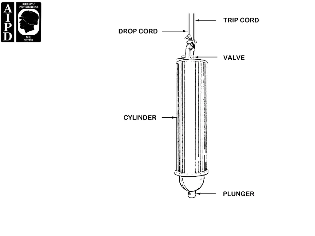
Bacon Bomb Sampler (Figure 6-1) – consists of a nickel-plated brass cylinder tapered at both ends and
fitted with an internal, plunger-type valve, and a drop cord. This sampler is used to take bottom samples
of liquid products of 2 psi or less RVP and samples of semiliquid products.<br>
slide102. Drum Thief Sampler – consists of a two-piece, plastic tube 39 ½ inches long and 1 ½ inches at maximum
diameter. The tube is fitted with two finger rings at the upper end and three supporting legs at the bottom.
Both ends are tapered and have openings. This sampler is used to take samples of liquid products of 12
psi or less RVP and samples of semiliquid products.
Core Thief Sampler – designed so that a sample can be obtained from the bottom ½ inch of the car or
tank. One type is lowered with valves open to permit the oil to flush through the container. When the thief
strikes the bottom of the tank, the valves shut automatically. The other type has a projecting stem on the
valve rod which opens the valves automatically as the stem strikes the bottom of the tank.<br>
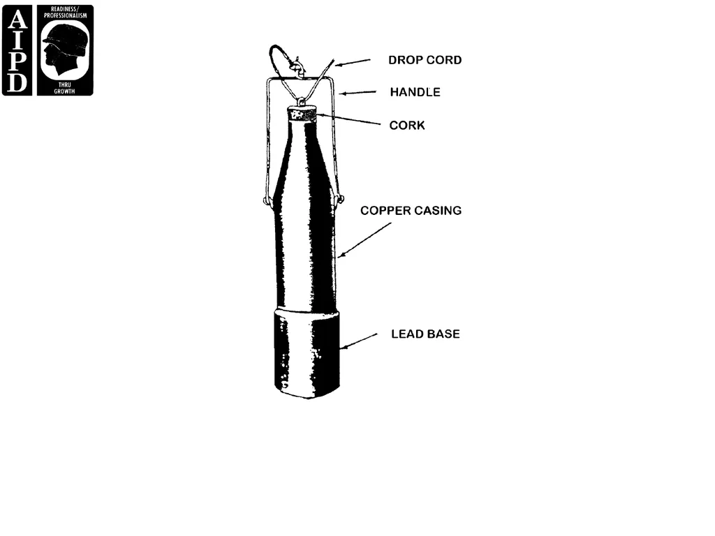
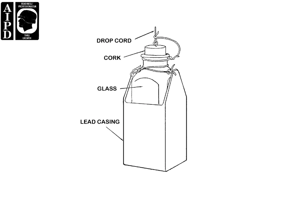
slide103. Bottle/Beaker Sampler (Figure 6-2 and 6-3) – the weighted copper beaker sampler consists of a copper
bottle permanently attached to a lead base and a drop cord. This sampler is used to take upper, middle,
lower, or all-level samples of liquid products of 16 psi or less RVP. The weighted bottle sampler consists
of a glass bottle within a square, weighted metal holder and a drop cord. This sampler has the same
application as the weighted beaker sampler, but with its wider mouth, it can be used for sampling heavier
products.<br>
slide105. Extended Tube Sampler – consists of a flexible tube connected to the suction of a manually operated
pump. The tubing is attached to the weighted end of a conductive wire or tape. This sampler may be
used only for obtaining bottom water samples.
Closed Core Thief Sampler - designed so that a sample can be obtained from the bottom ½ inch of the
car or tank. It has a uniform cross section and bottom closure with a capacity depending upon the size of
the sample required, and it may be used for sampling crude petroleum.
Manual Sampling Probes – used to withdraw from the flowing stream a portion that will be representative
of the entire stream.
Dipper (size relative to sample size desired) – consists of a flared bowl and a handle of convenient length,
made of material such as tinned steel that will not affect the product being tested. The dipper should have
a capacity suitable for the amount to be collected and must be protected from dust and dirt when not in
use.<br>
slide107. Tube Sampler – either a glass or metal tube may be used, designed so that it will reach within about 1/8
inch of the bottom and have a capacity of approximately 1 pint. or quart. This procedure is applicable for
sampling liquids of 2 psi RVP or less and semiliquids in drums, barrels, and cans.
Vacuum Pump Sampler – consists of a tube, plunger handle, and tubing. It has an outside diameter of 1
¼ inches and is 7 inches long. The sampler can lift about 25 feet of water at sea level.
Thermometers.
Polyethylene Pails.
Sample Containers and Materials.
- Glass (clear and dark).
- Metal.
- Aluminum or steel scoops.
- Labeling materials.<br>
slide108. Sampling and Gaging Kit.
Gaging Equipment.
- Tape and bob.
- Petroleum gage stick.
- Tank vehicle gage stick.
- Yardstick.
- Tank car gage stick<br>
slide109. PART B - CHECKING PROCEDURES USED TO OBTAIN THE
TEMPERATURE OF PETROLEUM PRODUCTS
Temperature Measurement. Because the volume of petroleum products increases or decreases in
direct proportion to temperature increase and decrease, accurate measurement of the temperature of a
product must be taken at the time of gaging. The measured quantity must be corrected to the standard
temperature of 60F for volumes over 3,500 gallons. When gaging large quantities, take temperature
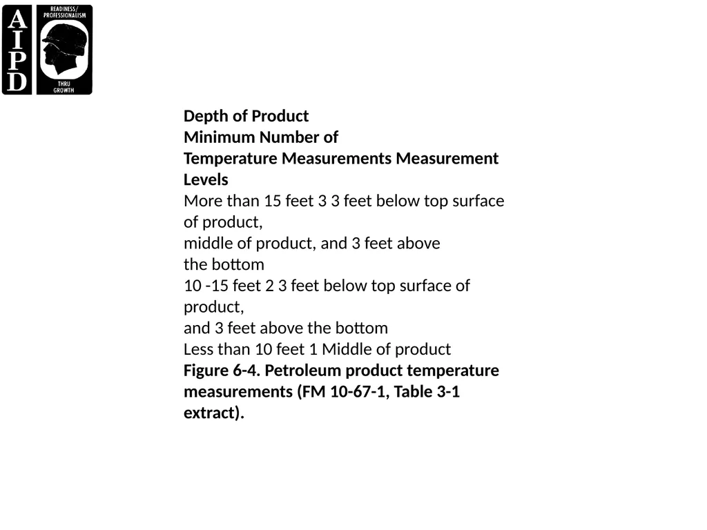
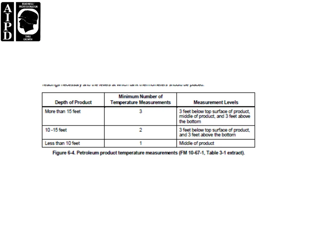
readings at various levels and average them to determine the true average temperature of the product. Table
3-1 of FM 10-67-1 (Concepts and Equipment of Petroleum Operations) (Figure 6-4) shows the number of
readings necessary and the levels at which tank thermometers should be placed.<br>
slide110. Depth of Product
Minimum Number of
Temperature Measurements Measurement Levels
More than 15 feet 3 3 feet below top surface of product,
middle of product, and 3 feet above
the bottom
10 -15 feet 2 3 feet below top surface of product,
and 3 feet above the bottom
Less than 10 feet 1 Middle of product
Figure 6-4. Petroleum product temperature measurements (FM 10-67-1, Table 3-1 extract).<br>
slide112. Measuring Instrument. The cup-case thermometer (Figure 6-5) is used to measure the temperature of
a product in storage tanks. The thermometer is attached to a hardwood backing with the base of the mercury
column extending into the cup case. The cup case, when filled with liquid under measurement, minimizes
fluctuation of the reading when the thermometer is suddenly withdrawn from the tank. The minimum
immersion time for the cup-case thermometer in various petroleum products is given in Table 3-2 of FM 10-
67-1 (Figure 6-6). To avoid the long immersion time required for measuring the temperature of heavy fuel oils,
it may be practical to leave thermometers suspended in the tanks at all times.<br>
slide114. PRODUCT
TIME
(MINUTES)
Automotive gasoline (MOGAS), aviation gasoline
(AVGAS), kerosene, diesel fuel, jet fuel, and
grades 1 and 2 burner fuel oil
5
Grades 4, 5, 6, and Navy Special burner fuel oil 15
NOTE: This conforms to Table IV, Minimum Immersion Time for Cup-Case Assembly, API Standard
2543, ASTM Designation D 1086. Product listings are not comprehensive.
Figure 6-6. Minimum immersion times for the cup-case thermometer (FM 10-67-1, Table 3-2 extract).<br>
slide116. Measuring Procedures. To measure the temperature of petroleum products in storage tanks, the
following procedures are used:
The thermometers are inspected for separation of the mercury column, and any faulty thermometers are
replaced. Separation of the mercury column results in incorrect readings. Each thermometer is checked
for accuracy by comparing the readings of a number of thermometers exposed to atmospheric
temperature at the same time and location. Any thermometer that has a reading deviation from the other
readings by more than 0.5F is replaced.
The cup case is attached to the end of a gage tape or suitable cord.
The thermometer is then lowered to the required product level and allowed to remain at this level at least
as long as the minimum time specified in Table 3-2 of FM 10-67-1 (Figure 6-6).<br>
slide117. The thermometer is then withdrawn and read immediately with the cup sheltered below the edge of the
hatch to minimize any change of reading that may be caused by wind or atmospheric temperature. The
cup must be full when withdrawn, and the product must not be spilled from the cap when taking a reading.
As quickly as accuracy will permit, the temperature is recorded to the nearest 0.5F.
When readings are taken at more than one level, all readings are added and divided by the number of
readings in order to obtain the true average temperature of the product. For example, assume a tank had
20 feet of product in it. You would take recordings at 3 feet, 12 feet, and 21 feet, according to Table 3-1 of
FM 10-67-1 (Figure 6-4). Assume that readings of 82 F, 81 F, and 80F were obtained. Add these
readings and divide by three to get an average temperature.<br>
slide118. PART C - CHECKING GAGING PROCEDURES
Accurate gage readings, temperature API gravity, and the volume of bottom sediment and water (BS&W) are
necessary to calculate the net volume of petroleum at the standard temperature of 60F. Gages are
determined through specified gaging hatches in tanks, ships, barges, tank cars, and tank trucks. There are
two basic types of procedures for obtaining gages: innage and outage. Normally, outage gage is used for
vessels and railcars, and innage gage is used for storage tanks. Bulk petroleum products are often handled
many times before they are used. Throughout this handling, they must be rigidly accounted for, and accurate
quantity records must be maintained at all times. For accountability purposes, products must be gaged
periodically to determine the quantity of products on hand, verify of quantities received or issued, detecting
leaks or unauthorized withdrawals, determine presence and amount of BS&W, and determine the terminal
capacity for receiving shipments. Accounting for all receipts, issues, transfers, and operational gains and
losses of bulk petroleum products is a major responsibility of the terminal accountable officer.<br>
slide119. Gaging Terms. The following gaging terms are used:
Innage. The depth (height or volume) of product in a tank measured or gaged from the surface of the
product to the tank bottom.
Outage (Ullage). A measurement of the free space above the surface of the product extending to the
reference mark.
Reference Mark. A horizontal line put in the rim of the gaging hatch representing a fixed point from which
measurements are made.
Datum Plate. A level metal plate at the tank bottom and directly under the reference mark. This plate
provides a smooth, level surface for the innage bob to rest upon.<br>
slide120. Reference Height. The distance from the reference mark to the tank bottom or datum plate. After the
reference height is established, it is stenciled in a conspicuous place adjacent to the gaging hatch.
Innage Tape and Bob. A graduated, metallic tape and pointed bob used to determine the amount of
innage in a bulk storage tank.
Outage Tape and Bob. A graduated, metallic tape and flat bob used to determine the amount of ullage in
a bulk storage tank.
Product-Indicating Paste. A chemical paste used in measuring the amount of liquid petroleum in a
storage tank. It will change color when it comes in contact with a petroleum product.
Water-Indicating Paste. A chemical paste used to differentiate between liquid petroleum product and
water. The paste changes color when it comes in contact with water, but is not affected by petroleum
products.<br>
slide121. Tape Cut. The line made on the tape measuring scale by the product being measured.
Bob Cut. The line made on the bob by the BS&W being measured.
Opening Gage. A gage of a product taken before delivery, issue, or receipt of a product.
Closing Gage. A gage of product taken after delivery, issue, or receipt of a product.
Total Measured Quantity. Total measured quantity is the volume of product and BS&W in a tank at the
observed temperature of the product at the time of gaging. It is usually obtained from a tank's capacity
table or strapping chart.
Bottom Sediment and Water (BS&W). The amount of sediment and water measured in the bottom of a
tank.
Net Volume Uncorrected. The volume of product in a storage tank at the observed temperature.
Net Quantity at 60F. The net volume, uncorrected and converted to the equivalent volume at 60F.<br>
slide122. Gaging Equipment. Items of gaging equipment are described below.
Innage Tape and Bob (Figure 6-7). The steel innage tape is graduated to 1/8 inch, and the first whole
number on the tape is 9 or 10. Consequently, from the pointed tip of the conical bob to the first number on
the tape is 9 or 10 inches. From the tip of the bob to the top of the eyelet is 6.6 inches. The bob is made
of nonsparking metal, and "0" is at the bob's tip.<br>
slide124. Outage Tape and Bob (Figure 6-8). The steel outage tape is similar to the innage tape except that the
readings begin at the 2-inch level. The "0" reference is where the harness snap connects to the bob. The
rectangular bob is 6 inches long, but the 1/8-inch graduations start with the 6-inch mark at the bottom and
QM 5097 6-8
are read upward to 1 inch as the last whole number on the top. The outage bob has a flat nose and is
made of nonsparking metal<br>
slide126. General Precautions. General precautions for gaging are as follows:
Remove gaging device housing by unscrewing it carefully and slowly. If pressure exists, unscrew housing
two or three threads to relieve pressure. Do not unscrew housing completely or release gage-tube lock
with head or body over it as high pressure may cause the gage tube to rise rapidly.
Whenever there is a gage-tube safety latch, tighten the packing nut to prevent leakage and replace the
gaging device housing.
Use care in operating all valves and removing and replacing their plugs. Use open-end or socket
wrenches on the plugs, and do not apply much force on valves with broken stems.
If there is any pressure or sound of escaping vapor, the pressure must be relieved.
Be sure all loading connections are tight before operations are started. After shutting the supply valves,
release pressure in the line before disconnecting.
To test for leaks, spread soapy water or light mineral oil on the suspected part to aid in verification. Never
test with a flame.
If excess-flow valves close, it is necessary to close the operating valves to allow pressure to equalize.
Carefully regulate the rate of flow to prohibit an excessive rate of flow.<br>
slide127. Innage Method of Gaging. Gaging procedures for atmospheric and other non-pressure tanks using the
innage tape and bob are as follows:
Raise the appropriate hatch cover and locate the reference point.
Apply water-indicating paste to the bob and product-indicating paste to the tape at the expected level of
the product in the tank. Apply the paste thinly and to the graduated side of the tape.
The ungraduated side of the tape is held in contact with the metal rim of the gaging hatch at the reference
point as the tape is lowered into the tank.
The bob and tape are lowered into the tank until the bob is within a short distance of the tank bottom. This
can be determined by comparing the length of tape unwound from the reel with the reference height of the
tank.<br>
slide128. Continue to unwind the tape slowly until the tip of the bob just touches tank bottom or datum plate. The
bob must not rest on a rivet or other obstruction. If the tape is lowered too far, the bob will tilt and an
incorrect gage reading will be obtained as the product cut shown on the tape will be too high. The tape
reading at the reference point should be compared with the reference depth of the container to make sure
that the gage is accurate.
The tape should be withdrawn after at least 30 seconds, and the product cut on the tape should be read
and recorded as the innage gage. The water cut on the bob is read and recorded as the BS&W cut.
Two identical readings are obtained to ensure that the measurement is accurate. The same gaging
equipment and gaging hatches are used in obtaining both opening and closing gages, and the tape is
lowered to the same depth for both gages<br>
slide129. Outage Method of Gaging. The outage method is used for gaging barges and tankers. All safety
procedures apply. Gaging procedures for the outage method are as follows:
Apply product indicating paste to the length of the bob.
The bob and tape are lowered into the tank until the bob touches the surface of the product.
When the bob is motionless, the tape is lowered slowly until the bottom of the bob is 2 or 3 inches below
the surface of the product and an even inch graduation mark on the tape is at the reference point. The
reading on the tape at the reference point is recorded as the tape reading.
The tape is withdrawn quickly, and the product cut on the bob recorded as the bob reading. The scale is
read to the nearest 1/4 inch.
The bob reading is added to the tape reading to obtain the outage gage as shown in the following example:
Tape reading at reference point 21 feet, 6 inches
Bob reading + 3 3/4 inches
Outage gage 21 feet, 9 3/4 inches<br>
slide130. An outage gage can be converted to an innage gage if the tank being gaged is calibrated only in innage
measurements. The procedure is as follows:
Use the outage gage above (21 feet, 9 3/4 inches) and an assumed reference height of 50 feet.
The outage gage is 21 feet, 9 3/4 inches (point A to B). The reference height is 50 feet (point A to C).
The innage gage will be the distance from points B to C.
To convert outage to innage simply subtract the outage from the reference height:
EXAMPLE:
Reference Height - Outage = Innage Gage
50 feet - 21 ft, 9 3/4 inches = 28 ft, 2 1/4 inches
Bob cuts for BS&W in the outage method must be done with an innage bob as described previousl<br>
slide131. Volume Correction. The volume of liquid petroleum products changes because of changes in
temperature. Therefore, gaged volumes in excess of 3,500 gallons must be corrected to account for this
change of volume. When the observed temperature is above 60F, the observed volume is reduced to 60F
because expansion has taken place. However, when the observed temperature is below 60F, the observed
volume is increased to the volume at 60F because contraction has taken place.<br>
slide132. DA Form 3853-1 (Innage Gage Sheet (Using Innage Tape and Bob)) (Figure 6-9) will be used to record
volume correction data. All tanks have individual strapping charts or tank calibration tables which show the
volume of product in the tank per foot, per inch, and even per fractions of an inch, usually 1/8 inch. Using the
physical gage (product and BS&W) measurements, the gager can determine the total volume of product in the
tank. By using the same tank table, the gager determines the volume of water in the tank. The volume, and
only the volume, of petroleum products is left.<br>
slide134. You must remember to subtract volume from volume, never inches from inches. The resulting figure is at the
observed temperature and is ready to be corrected to volume at 60F. To determine the multiplier necessary
to convert the volume at observed temperature to the volume at 60F, one would need an average tank
temperature and the API gravity of the product. Example of volume correction (innage gaging):
Tape Cut Reading: 6 feet, 3 5/8 inches
Bob Cut Reading: 0 feet, 1 1/8 inches
Tank Temperature: 67.5F
API Gravity at 60F 56.3 (JP-4)<br>
slide135. STEP 1. Convert gage readings to gallons.
Bob cut of 0 feet, 1 1/8 inches converts to 255.6 gallons.
The tape cut of 6 feet, 3 5/8 inches converts to 17,181.4 gallons.
STEP 2. Subtract the BS&W (bob cut volume) from the total volume to get the uncorrected net volume of the
fuel.
17,181.4 gallons - 255.6 gallons = 16,925.8 gallons
STEP 3. Find the volume correction factor in ASTM Petroleum Measurement Table 6B.
Round the API gravity at 60F to the nearest 0.5 API. 56.3 rounds to 56.5.
Locate the tank temperature of 67.5F in the extreme left-hand column.
Go across from 67.5 until you are under the rounded API gravity of 56.5.
The volume correction factor is 0.9950.
STEP 4. Multiply the uncorrected net volume from step 2 (16,925.8 gallons) by the volume correction factor
in step 3 (0.9950).
16,925.8 X 0.9950 = 16,841.2
STEP 5. Round out the result to the nearest gallon and report as 16,841 gallons at 60F.<br>
slide136. Review Quantity Calculations on DA Form 3853-1 and Gaging Records for Accuracy.
As supervisor of a petroleum supply unit, you must ensure that all quantity calculations and gaging records
generated by petroleum supply personnel are accurate. Mistakes or oversights on quantity calculations and
gaging records could lead to the recommendation of the improper disposition of a large quantity of fuel that
may or may not be contaminated. The steps that may be taken to ensure the accuracy of calculations on DA
Form 3853-1 and gaging records are as follows:<br>
slide137. Ensure personnel are familiar with gaging procedures and cautions outlined in FM 10-67-1, MIL-HDBK-
200 (Quality Surveillance Handbook for Fuel, Lubricants, and Related Products), and AR 710-2 (Inventory
Management Supply Policy Below the Wholesale Level).
Periodically spot-check the calculations and conversions against records and tables.
Assign technicians the task of checking fellow technicians’ calculations and records for accuracy.
Provide continuous training for lab personnel with regard to gaging procedures.
Ensure all entries on DA Form 1358-1 are clear and legible.<br>
slide138. responsible individual. At minimum the following entries must be reviewed for possible inaccuracies:
API Gravity.
Tape Reading.
Bob Reading.
Net Volume (uncorrected).
Average Temperature.
Multiplier.
Net Quantity (at 60F).<br>
slide139. PART D - ASTM METHOD D- 4057 SAMPLING PROCEDURES
Samples of petroleum and petroleum products are examined by various methods of testing for the
determination of physical and chemical characteristics. It is necessary that the samples be truly
representative of the petroleum products in question. The precautions required to ensure the representative
character of the sample are numerous and depend upon the type of material sampled, the source from which
the sample is obtained, the type and cleanliness of the sample container, and the sampling procedure that is
used. A summary of sampling procedures and their application is presented in this lesson. Each procedure is
suitable for sampling a number of specific materials under definite storage, transportation, and container
conditions. The basic principle of each procedure is to obtain a sample or a composite of several samples in
a specific manner and from specific locations in a tank or other container in order that the sample or
composite will be truly representative of the petroleum product(s) being tested<br>
slide140. Types of Samples. A sample is a small portion of a substance used to inspect or to determine the quality
of the total substance. The various types of samples of petroleum products are listed below:
Top Sample. A sample taken with a weighted bottle or beaker sampler from a depth of about 6 inches
below the surface of the tank's contents.
Upper Sample. A sample taken with a weighted bottle or beaker sampler from the middle of the top third
of the tank's contents.
Middle Sample. A sample taken with a weighted bottle or beaker sampler from the middle of the tank's
contents.
Lower Sample. A sample taken with a weighted bottle or beaker sampler from the middle of the bottom
third of the tank's contents.
Bottom Sample. A sample taken with a bacon bomb or thief sampler from material present on the bottom
of a tank.
All-Levels Sample. A sample taken by submerging a stoppered, weighted bottle or beaker sampler to a
point as near as possible to the tank draw off point, opening the sampler, and raising it at a constant rate
so that it is 75 to 85 percent full when it emerges from the liquid.
Average Sample. A sample that consists of proportionate parts from all levels of the container. For
example, an average sample from a horizontal, cylindrical tank or from a spherical tank should contain
more material from the middle of the tank where the diameter is greatest.<br>
slide141. Composite Sample. A sample combining individual samples that represents the bulk of the product from
which it was taken.
- Single tank composite sample. A sample that is a blend of the upper, middle, and lower samples from
a tank's contents.
- Multiple tank composite sample. A sample that is a proportionate blend of individual, all-levels
samples taken from compartments containing the same grade of product. The sample consists of
parts in proportion to the volume of product in each compartment sampled.
Outlet Sample. A sample taken with a weighted bottle or beaker sampler at the level of a tank outlet,
whether fixed or swing line.
Drain Sample. A sample taken from the water drain-off or discharge valve.
Continuous Sample. A sample taken from a flowing pipeline in such a manner that the sample is a
representative average of the stream during the period of sampling.
On-Line Sample. A sample taken from a flowing pipeline by opening a valve and collecting the sample
during the flow of the product.<br>
slide142. Sampling Procedures. A simple set of sampling procedures cannot be given because products are
different; the method of transportation and storage are different. Sampling requirements of many tests are
different. A few important sampling points are as follows:
Representative Sample. A sample must represent the entire quantity of product sampled. Otherwise, the
resulting analysis can only reflect the quality of a portion of the whole substance, and the quality reflected
may be better or worse than the true quality.
Size of Sample. The normal size of a sample is 1 gallon for liquids and 5 pounds for semisolids. Special
samples and gasoline samples for testing performance number by the super charger method should be 5
gallons. Samples of jet fuel to be tested for thermal stability should be 5 gallons.
Standard Sampler. The sampler should be one of the standard types (ASTM D270) and the one best
suited to the product and to the carrier or container. However, in situations where a standard sampler is
not suitable because of the small opening through which the sample must be taken, an improvised
sampler can be used. In any case, the sampler must be clean and made of a material that will not
contaminate the sample<br>
slide143. Cleaning the Sampler. Rinse sampler and container with the product being sampled.
Protecting Samples. All sample containers should be protected for shipment. Samples of gasoline, jet
fuel, and kerosene should be protected from direct sunlight by using brown bottles or cans or by covering
clear bottles with paper or foil. Samples of gasoline and JP-4 should be kept cool (30 to 40F) if possible
to prevent loss of light ends. Samples of product containing lead additives must be protected from
sunlight.
Sample Numbers. A sample number should be assigned to each sample and entered on the sample tag.
This number is made up of the last two digits of the calendar year and the sample number for that year.
6-13 QM 5097
For example, the first sample from an activity for 1998 is number 98-1. A station log should be kept with a
record of samples submitted to the designated testing laboratory.<br>
slide144. PART E - VERIFYING SAMPLE INFORMATION IS COMPLETE
Sample Numbers. Ensure that the proper numbering convention (for example, unit’s first sample from
1998 = 98-1), and that there are no duplication or skipping of numbers assigned from your unit.
Laboratory Log. A log should be maintained as a permanent record of samples received for testing. The
following information should be entered on the sample tag:
Date of receipt.
Type of product.
Unit sample number.
Source of the sample.
Quantity the sample represents.
Sampler's name.
Date sampled.
Date of completion of tests.<br>
slide145. PART F - SAFETY PRECAUTIONS FOR HANDLING SAMPLES
A sampling and gaging SOP should be developed for your unit according to the specific mission assigned.
The following safety precautions should be known/available to all assigned personnel handling samples:
Before a tank is gaged, static electricity must be grounded by touching the bare hand to the tank shell (or
handrail).
When possible, tanks should be gaged from the side of the gaging hatch with the wind at your back, and
caution should be exercised against breathing vapor from the contents of the tank.
Tanks should never be gaged during an electrical storm.
When gaging must be done from the roof, personnel should stand at the same location on the roof for
both opening and closing gages.
Innage gaging should be to the nearest 1/8 inch. Outage gaging is done to the nearest 1/4 inch.<br>
slide146. Gaging should be repeated until two gagings are identical.
The tape should touch the rim of the gaging hatch at all times to ground static electricity.
The tape should be wiped clean and dry after each use.
After the product has been discharged into a tank, it should stand at least 30 minutes to eliminate static
electricity.
A product temperature reading for volume correction should be taken immediately before or after volumes
of 3,500 gallons or over are received or issued.
Use the same tape and bob for opening/closing gages.
All personnel, in addition to being familiar with specific safety measures for sampling and gaging, should also
be familiar with the general safety precautions outlined in the fire prevention and safety SOP<br>
slide147. PART G - ENVIRONMENTAL CONSIDERATIONS
Environmental considerations should always be taken into account, especially when performing sampling and
gaging operations. The fire prevention and safety SOP should be used to the fullest extent possible. Some of
the considerations that will need to be addressed in relation to sampling and gaging SOP are as follows:
Storage Procedures.
Hazardous Materials Handling.
Spill Containment and Cleanup.
MSDS and HMIS.
SPCC and ISCP Procedures<br>
slide148. Guidelines and procedures for testing of petroleum products must also be contained within the sampling and
gaging SOP. Listed below are some of the general requirements; more detailed information can be found in
MIL-HDBK-200.
To determine the minimum frequency of sampling and testing, you would refer to MIL-HDBK-200, Tables
II and III (Figure 6-10 and 6-11). With these tables and the information obtained from the DA Form 1804
(Petroleum Sample) Tag, you can determine what type of minimum test is required to be performed on the
samples taken (such as type A, B-1, B-2, B-3, or C test). The same tables list the type of samples to be taken
(such as an upper, middle, lower, composite, all-level, line sample or a representative sample for packaged
products).
The proper size of the sample is covered in paragraph 5.4, MIL-HDBK-200. Normally, liquid samples
submitted for analysis will not be less than 1 gallon in size; semisolids will not be less than 5 pounds.
Special samples and gasoline samples requiring ASTM aviation supercharge method of determining
performance numbers will be of 5-gallon size unless otherwise directed. Samples of jet fuel requiring full
specification tests will be 5 gallons<br>
slide150. PART I - DA FORM 1804 COMPLETION
The following information must be entered on DA Form 1804 (Figure 6-12) for each sample taken and/or
submitted:
Product.
From (Requesting Activity).
Sample No. (Entered by lab).
Laboratory No.
Specification No.
Amt. Product Sample Represents.
From (Where sample was taken from).
Source (What storage type sample was taken from: Truck No., Tank No., Other).
Sampled By (Individual).
Stock Number.
Date Sampled.
Shipment Delivery Date.
Fuel Origination.
Sample Type.
Figure 6-12. DA Form 1804 (Petroleum Sample).
DA<br>
slide152. PART J – PETROLEUM SUPPLY QUALITY SURVEILLANCE SOP
As a senior petroleum NCO, you have by now become quite familiar with SOPs. While most SOPs cover
procedures related to certain functions, ensuring that they are accomplished in an efficient and effective manner,
the petroleum supply quality surveillance SOP is designed to encompass all aspects of quality surveillance related
to petroleum operations. The following standard format will be used in order to ensure the coverage required for
an effective and efficient SOP:<br>
slide153. Unit Location - Using unit location.
References - Applicable references used to develop SOP.
Required Content - SOP content.
Purpose - Tell the reason you are establishing the SOP.
Scope - Specify procedures and requirements to be covered by the SOP.
Responsibility - Responsible personnel for each set of procedures
Procedures - State which operating procedures are to be used.
Miscellaneous - Any additional pertinent information to be included.
Definition Section - Definitions of terms.
Signs and Symbols - Explanation of symbols and/or signs used.
Special Instructions<br>
slide154. Your main responsibility in developing and maintaining a petroleum supply quality surveillance SOP will be to
ensure that all procedures are pertinent to your unit’s particular mission. The following areas (depending on the
local situation will be addressed throughout this course) should be addressed in the SOP as a minimum:
Policies and procedures for determining and maintaining petroleum quality during storage.
Policies and procedures for determining and maintaining petroleum quality while loading and unloading
tankers and barges.
Policies and procedures for determining and maintaining petroleum quality while loading and unloading
tank vehicles and tank cars.
Policies and procedures for determining and maintaining petroleum quality during pipeline operations.
Quality standards for aviation fuels.
Sampling and maintenance procedures for filter/separators.
Marking procedures for petroleum containers and equipment.
Environmental and safety considerations for petroleum quality surveillance operations.
Other quality surveillance procedures as dictated by higher headquarters.<br>
slide155. Once you have developed and established the petroleum quality surveillance SOP, it is your additional duty to
ensure that you and your subordinates integrate it into your unit’s everyday work requirements. This can be
accomplished first by ensuring that all personnel have a physical copy that they can familiarize themselves with.
Other ongoing ways to enforce compliance can take the form of scheduled and unscheduled inspections, drills,
testing, and routine observations.<br>
FIRE AND SAFETY
Critical Task:
101-519-431<br>
slide3. INTRODUCTION
Because of the very nature of petroleum products, there are many hazards involved in the handling and storing of
them. The greatest and most obvious is fire. However, we must not overlook the many health and safety hazards
in addition to fire that are also present in petroleum facility operations. As a senior NCO, you are responsible for
the fire prevention and safety program best suited to your petroleum facility. In addition you must ensure through
periodic training, drills, and inspections, that petroleum personnel in your area of responsibility are knowledgeable
of the fire and safety precautions and procedures discussed below.<br>
slide4. PART A – FIRE AND SAFETY TRAINING, INSPECTIONS, AND DRILLS
Your duties and responsibilities as a senior petroleum NCO often require you to ensure that procedures and
policies are being carried out. When dealing with petroleum, it is clear that fire and safety are probably the most
important considerations that you must make when developing general procedures and specific SOPs.
Fire and Safety Training. Fire and safety training begins when the soldier receives initial MOS
training and continues all the way through the soldier’s career. Given that the personnel in your unit will be in
almost constant contact with highly flammable products, fire and safety training will be an ongoing function.
Training should be incorporated into every function your unit performs. When developing an SOP, a periodic
training program should be incorporated into the procedures, ensuring that all personnel know and practice all
applicable fire and safety precautions and practices. Planned drills are an excellent way to enforce training
requirements and provide you as the senior NCO with an effective measurement tool that ensures personnel
training is sufficient.<br>
slide5. Inspections. Periodic planned and surprise inspections can also allow you to ensure that personnel are
following all applicable procedures related to fire prevention and safety. Most importantly , inspections can serve
to show you in what areas you may need to stress training, allowing you to develop a more complete training
program related to petroleum fire and safety. Some of the areas that you will need to establish inspection
procedures and intervals for are as follows:
Work area hazards.
Fire fighting and safety equipment.
Fire reporting and fighting procedures.
First-aid supplies and procedures.
Locations and availability of pertinent fire and safety information.
Fire and safety training records.
Fire and safety precautions and procedures during the performance of duties.<br>
slide6. PART B – NATURE AND CLASSES OF FIRES
Nature of fire.
Three elements are required to start and sustain a fire:
Heat (source of ignition) such as sparks, open flame, or static electricity.
Oxygen (air) which is always present.
Fuel (vapors) which in petroleum operations includes items such as MOGAS, diesel fuel, and JP4.
By ensuring that personnel know how to remove or prevent the presence of any one of these elements, a fire
can be easily prevented or extinguished.<br>
slide7. Classes of Fires.
There are four main classes of fire that you must ensure your personnel are familiar with. They are based on the
combustion characteristics of the material that is ignited:
Class A fire - These fires occur in combustible materials such as bedding, mattresses, books, cloth,
wood, and paper. The remains of these fires are charred embers.
Class B fire - These fires occur in flammable liquids such as gasoline, jet fuels, kerosene, oils, paints,
turpentine, grease, and tar.
Class C fire - These are electrical fires, and they can occur in wiring, electrical switches, and generators.
1-3 QM 5097
Class D fire - These involve combustible chemicals and metals such as sodium, potassium, titanium,
magnesium, zirconium, and phosphorous.<br>
slide8. PART C – CHARACTERISTICS AND SOURCES OF FIRE AND SAFETY
HAZARDS
Vapor Characteristics. In a fire, it is the vapor that actually burns. Characteristics of vapors
include:
Vapors are heavier than air and collect in low areas.
Vapors will hang low to the ground and spread over large areas.
On hot humid days vapors are produced in greater volume.
When vapors are allowed to collect, flashbacks can occur as the vapors come in contact with a heat
source and the heat travels back to the source of the vapors, causing a fire and possibly an explosion.
A 1- to 8-percent ratio by volume of vapors when mixed with air, will form an explosive range. An
explosive range is that point where the vapor and the air mixture will burn. A mixture above 8 percent is
too rich in vapors and will not ignite. A mixture below 1 percent is too lean in vapors (too rich in air) and
will not ignite.<br>
slide9. Control of Vapors.
Empty containers (5 gallon, 55 gallon) that have previously contained petroleum product are more
dangerous than full ones. Fill such containers as soon as possible, or when they are stored empty,
ensure caps and bungs are on tight.
Store containers that have fuel in them or containers that previously contained product in a safe area.
Do not overfill or fill containers at too fast a rate as vapors will be displaced to the atmosphere and
become a hazard.
Repair leaking pipes and containers as soon as possible.
Clean up spills immediately (as long as the contamination is present, vapors are a hazard).<br>
slide10. Sources of Ignition. A source of ignition can be either a flame, spark, or other heat-generating
source. Some of the most common causes of heat are:
Smoking material (matches, lighters, and cigarettes).
Sparks (static electricity, moving fuel, moving equipment, welding and cutting).
Spontaneous combustion (oxidation and chemical reaction).<br>
slide11. As a minimum, you should post “No smoking within 50 feet” signs in critical areas of the facility and enforce
the rule. Other precautions should also be observed/practiced, such as:
Designate all smoking areas at least 100 feet away from refueling operations.
In very hazardous areas, collect smoking materials at the entrance to the facility and keep them in
separate airtight containers at the entrance to the facility.
Welding and grinding should only be done under controlled conditions (that is, fire department notified,
vapor freeing completed, or when product in a pipeline is moving).
Electrical equipment must be maintained in safe working condition (approved electrical fixtures), and
grounding and bonding procedures must be utilized to minimize static electricity and arcing.
Ensure dispensing and receiving equipment is bonded and grounded.
Bottom load whenever possible, as top loading generates static electricity and splashing while filling.
Ensure that all personnel involved in gaging activities are trained to always bond themselves before
gaging storage tanks and tank vehicles.
Before gaging and sampling, allow a minimum of 30 minutes for the static charge to dissipate from fuel
receipts.
Always ensure that all fire extinguishers are in place and are operational.<br>
slide12. PART D - TYPES OF FIRE EXTINGUISHERS AND INSPECTION
PROCEDURES
Types of Fire Extinguishers.
There are four types of fire extinguishers your personnel should be familiar with: water, carbon dioxide, dry
chemical, and Halon.
Water extinguishers (pumped or pressurized) - May be used for Class A fires. This type of extinguisher
is used to control the heat. DO NOT USE for electrical, combustible metal, or flammable liquid fires.
Carbon dioxide extinguishers - May be used on electrical, chemical, or petroleum fires (Class B, C, and
D). This type of extinguisher controls the fire by diluting the air, thus choking the fire.
Dry chemical extinguishers - May be used on Class B, C, and D fires. This type of extinguisher is used
to smother the fire.
Halon extinguishers - Are effective against Class A, B, and C fires. The Halon extinguisher works
chemically to stop the combustion process. The agent, discharged as a liquid becomes a gas when it
contacts the fire.<br>
slide13. Inspection Procedures.
You must ensure that fire extinguishers are inspected at least monthly for serviceability. Any fire extinguisher
found unserviceable or discharged should be taken to the fire station for repair or recharging. The areas on the
extinguisher to be checked are:
In the body, check for dents, cracks, and excessive rust.
In the hose, check for dry rot, cracks, and missing parts.
Ensure that the seal is intact.
Ensure that the pressure gauge is in the “green,” fully-charged position.<br>
slide14. PART E- PRINCIPLES OF EXTINGUISHING FIRES
There are three basic methods your personnel will use to control and/or extinguish a fire:
Control the heat - Cooling or reducing the temperature of the fire below the ignition point will remove the
source of heat and control the fire.
Control the air - By reducing or eliminating oxygen in the air, combustion will no longer be supported. Air
is diluted by reducing the percentage of oxygen to the point where it will no longer support combustion. If
all air is cut off at the surface of combustion, a fire is smothered.
Control the fuel - Removing the combustible material or shutting off the flow of fuel will control the fire<br>
slide15. General Procedures to Extinguish a Fire. As a petroleum manager you can use drills or
other testing methods to ensure that your personnel are aware of the sequence of steps to take when a fire is
discovered. The recommended sequence is as follows:
Sound the alarm.
Call the fire department.
Determine the class of fire (A, B, C, D).
Select the appropriate fire extinguisher.
Stand upwind so that the flames and smoke blow away from you.
Point the fire extinguisher nozzle at the base of the fire.
Move the nozzle from side to side until the fire is extinguished<br>
slide16. PART F - FIRE FIGHTING TOOLS, CLOTHING, AND SAFETY TECHNIQUES
Tools. There are several types of tools used to fight ground cover fires. As a senior petroleum NCO, you should
ensure that the following items are on hand and in serviceable condition for all petroleum operations:
Rakes - Rakes are used to rake ground cover and dirt and to chop light growth. The types of rakes used
are as follows:
McLeod.
Council.
1-5 QM 5097
Rich Tool.
Fire Swatters - The fire swatter, or flapper, is used to beat the flames out. It may be effective on small
fires, but it could cause a fire to spread due to flying embers.<br>
slide17. Clothing. When faced with fighting a brush fire, nothing is more important to success than having the proper
equipment. An integral part of fire fighting equipment is clothing. It is your responsibility to ensure that there is
adequate clothing on hand for any type of fire fighting situation that may arise. The type of clothing required varies
in relation to your mission and the type of fires that may occur. When planning operations, as well as ensuring
base-unit readiness, you must always consider the availability of the proper fire fighting clothing.<br>
slide18. Safety Techniques. As a senior NCO, you should ensure that personnel are thoroughly familiar with the
following techniques for fighting a ground cover fire:
Always know the current escape routes.
Safety may be gained by moving into the burned area (as a last resort only).
Always work a fire on a slope from below.
Always work downwind of a fast-moving fire.
Use caution in felling or cutting trees.
Pace yourself; ground cover fires usually require long periods of hard work.
Stay with your crew.
When working on the fire line, stay 10-15 feet from the nearest co-worker.
Post a lookout to watch for a change in the fire’s behavior.
Work as a crew; this is not a contest to see who can cut the most line.
If you find yourself surrounded by fire, dig a pit and cover yourself with dirt.<br>
slide19. PART G – GENERAL PETROLEUM HEALTH HAZARDS
Dusts. Dust results from the grinding, scraping, sanding, or sandblasting of tanks, especially in the case of
tanks that have held leaded fuels. Lead dust can also result from burning sludge taken from leaded gasoline
storage tanks. Lead, manganese, mercury, arsenic, and any compound made of these items can produce
dust that is poisonous to the body. Silica dust resulting from the operation of grinding and polishing machines
or sanding and sandblasting operations can be fibrous-producing, causing injury to the lungs. Nuisance dusts
may cause inflammation and respiratory ailments.<br>
slide20. Gases and Vapors. The terms "gas" and "vapor" are often used to mean the same thing, although there is
a difference. A gas exists as a gas at ordinary temperature and pressure. A vapor is a gas-like form of a
substance that is ordinarily a liquid. Gasses and vapors are divided into four groups. Poisonous or toxic
gasses and vapors have various effects on the body. They may injure or destroy the visceral organs, the
blood-forming system, tissues, or bones. Examples of poisonous gasses or vapors are hydrogen sulfide
found in crude oil of high sulfur content and tetraethyl lead vapor from leaded gasoline. You must avoid
exposure to them at all times. Simple asphyxiates are gasses and vapors that keep the lungs from getting air.
In other words, they replace oxygen that is in the air. Anesthetic gasses and vapors have a narcotic effect,
depressing the central nervous system to the point where respiratory failure may occur. All hydrocarbon
vapors have this effect. Irritant gasses and vapors inflame the lungs and respiratory tract. They may cause
pneumonia and other pulmonary diseases or make the victim more susceptible to them. Most flammable
gasses and vapors are irritants whether or not they are poisonous or narcotic.<br>
slide21. PART H - FIRST AID FOR SITUATIONS INVOLVING PETROLEUM
PRODUCTS
When personnel swallow petroleum products, assisting personnel should:
Keep the victim calm, if possible.
DO NOT INDUCE VOMITING.
Get the victim to medical help immediately.
In the eyes:
Flush the eyes for several minutes with clean water to try to remove the product.
Cover the eyes for several minutes with a sterilized dressing, and prevent the victim from rubbing the
eyes.
Seek medical help immediately.
On the clothing:
Remove the clothing after soaking the fuel-soaked clothing first with water. (This should prevent
sparking.)
Wash with soap and water and rinse thoroughly.
Get to medical help, if needed<br>
slide22. PART I - ACCIDENT REPORTS
Accident reporting is a very important aspect of a fire and safety program. Accident reports allow all personnel,
from the front line supervisor to senior doctrinal planners, to track and quantify safety-related trends that may lead
to changes or revisions in Army or even DOD policy related to doctrine and general procedures. By ensuring the
proper completion of accident reports, you, as a supervisor, are providing useful data that may be used to effect
changes in unsafe procedures and practices that in turn will save lives in the future and provide for a more efficient
and effective Army. Instructions for the use and procedures for properly completing DA Form 285 can be found in
AR 385-40.<br>
slide23. PART J - PETROLEUM FIRE PREVENTION AND SAFETY SOP
All of the information provided in this lesson would be useless if it were not documented and used to establish a
standard set of daily operating procedures that can be incorporated into your personnel’s everyday tasks. As the
senior NCO of your unit , you are responsible for developing a petroleum supply fire and safety SOP. The format
for most SOPs is standard and is provided in Appendix B of FM 10-426 (Petroleum Supply Units). Below is an
extract from FM 10-426, Appendix B. This format is designed to ensure a standard and complete set of
procedures related to the particular SOP being developed. It is important to realize that while this format dictates
the sequence and content requirements for an effective SOP, you must also include procedures that are peculiar
to your unit and overall mission<br>
slide24. Unit Location - Using unit location.
References - Applicable references used to develop SOP.
Required - SOP content.
Purpose - Tell the reason you are establishing the SOP.
Scope - Specify procedures and requirements to be covered by the SOP.
Responsibility - Responsible personnel for each set of procedures.
Procedures - State which operating procedures are to be used and intervals when applicable.
Miscellaneous - Any additional pertinent information to be included.
Definition Section - Definitions of terms.
Signs and Symbols - Explanation of symbols and/or signs used.
Special Instructions<br>
slide25. LESSON 2
PETROLEUM SUPPLY IN A THEATER OF OPERATIONS<br>
slide26. INTRODUCTION
In any major conflict, the anticipated tonnage associated with bulk petroleum products will account for over 50
percent of the total tonnage shipped into a theater of operations. The petroleum distribution system must be
flexible enough to meet the changing priorities of a fluid battlefield and reallocate resources as necessary.
Adjustments must be made to meet variations in intensity of warfare. As a petroleum NCO, understanding the
petroleum distribution system will assist you in planning for support<br>
slide27. PART A - DISTRIBUTING FUEL IN A THEATER OF OPERATIONS
The flow of fuel requirements begins with the submission of fuel forecasts from consuming units. Forecasted
fuel is then distributed as far forward as possible to satisfy the most forward needs first and then and only then
is any fuel placed in storage.
The using unit submits their forecast through the S4 channels to the Division Material Management Center
(DMMC). The DMMC prepares the division forecast from the main support battalion (MSB), forward support
battalion (FSB), and Aviation Brigade (AVN BDE) units logistics reports and forwards the requirements to the
Corps Material Management Center (CMMC).
The CMMC consolidates all the requirements from other divisional and nondivisional commands within the
corps area and forwards the entire corps forecast to the Theater Materiel Management Center (TMMC).<br>
slide28. PART B - UNITS RESPONSIBLE FOR DISTRIBUTION
Communications Zone. The communications zone (COMMZ) is the rear part of the theater of
operations and contains the lines of communication establishment for supply and evacuation and other
agencies required for the immediate support and maintenance of the field forces. The Joint Petroleum Office
(JPO) consolidates theater petroleum requirements for all services. prepares the “slate” (request for delivery
of fuel byproduct, quantity, and location), and forwards it to the Defense Energy Support Center (DESC). The
Petroleum Group operates the bulk petroleum distribution system extending from ports of entry through the
COMMZ and as far into the combat zone as practicable<br>
slide29. Combat Zone. The combat zone is the area required by combat forces for the conduct of operation. This
area is the territory forward of the Army rear area boundary.
Corps Area. The Corps Support Command (COSCOM), located in the corps area, provides combat service
support to Army forces in the corps area, direct support (DS) and general support (GS) to nondivisional units,
and GS to divisional units.
Petroleum Supply Battalion. Provides DS and GS petroleum in the corps and divisional areas.
Petroleum Supply Company. Receives, stores, and issues bulk petroleum to divisional and nondivisional
DS companies on a 24-hour basis. Receives fuel from the petroleum pipeline and terminal operating
company. Issues fuel to divisional and nondivisional DS supply and services companies and aviation
brigade and/or battalions. The capabilities and/or responsibilities of this organization are:
Install, operate, and retrieve approximately 10 miles of collapsible hoseline per day.
Maintain prescribed reserve stock supply.
Provide limited mobile filling station service.
Operate two to four supply points at different locations. Storage capacity includes twenty-eight
10,000-gallon collapsible tanks and twenty-four 50,000-gallon collapsible tanks for a total of
1,480,000-gallon capacity.<br>
slide30. Medium Truck Company (Petroleum). Provides transportation for bulk petroleum between GS and DS
petroleum organizations. The capabilities and/or responsibilities of this organization are:
Assigned sixty 5,000-gallon tanker trucks.
Can line haul 450,000 gallons of fuel each day. This is based on an assumption of 75 percent vehicle
availability and two round-trips completed each day.
Can local haul 900,000 gallons of fuel each day. This is based on an assumption of 75 percent
vehicle availability and four round-trips completed each day.
Has storage capacity of 300,000 gallons in the 5,000-gallon tanker trucks.
COSCOM Support Group. Provide area supply and services to units passing through or located in its
assigned corps areas.<br>
slide31. Supply and Services Battalion. Provides supplies and field services on a DS basis to nondivisional units
passing through or located in the corps area.
Supply and Services (S&S) Company DS. Provides direct support petroleum supply to nondivisional units
located in or passing through the corps area. Receives fuel from the Petroleum Supply Company. The
capabilities and/or responsibilities of the organization are:
Storage capacity of 120,000 gallons in two Fuel System Supply Points (FSSPs).
Assigned nine 5,000-gallon tankers.
Can line haul 81,900 gallons of fuel each day. This is based on an assumption of 75 percent vehicle
availability and two round trips completed each day.
Operate mobile filling stations when required<br>
slide32. Divisional Area. The Division Support Command (DISCOM), located in the divisional area, provides divisionlevel
combat service support (except COMSEC logistics, construction, financial services, legal services, and
public affairs) to all organic and attached elements of the division. Subordinate elements of the DISCOM are
the Main Support Battalion (MSB) and three Forward Support Battalions (FSBs).
MSB. Provides division-level combat service support to all organic and attached elements of the division.
The MSB provides direct support to units located in the Division Support Area (DSA) and backup to the
FSB.
Supply and Services (S&S) Company DS. Provides division-level supply and services to all organic and
attached elements of the division. The S&S Company provides direct support to units located in the DSA
and backup to the FSB’s Supply Company. Receives fuel from Petroleum Supply Company. The
capabilities and/or responsibilities of this organization are:<br>
slide33. Storage capacity of 304,000 gallons in two Fuel System Supply Points (FSSPs), two Forward Area
Refueling Equipment (FARE) systems, thirty-four 5,000-gallon tanker trucks, and two tank and pump
units (TPUs).
Can line haul 258,600 gallons of fuel each day. This is based on an assumption of 75 percent vehicle
availability and two round-trips completed each day.
Can local haul 517,200 gallons of fuel each day. This is based on an assumption of 75 percent
vehicle availability and four round-trips completed each day.
By doctrine, can handle only ground fuel (MOGAS and diesel).<br>
slide34. Forward Support Battalion (FSB). Provides brigade-level combat service support to all organic and
attached elements of the brigade.
Supply Company. Provides brigade-level petroleum to all organic and attached elements of the brigade.
Receives fuel from the Petroleum Supply Company and backup from the MSB AMS Company. The
capabilities and/or responsibilities of this organization are:
Storage capacity of 53,600 gallons in ten 5,000-gallon tanker trucks and two tank and pump units.
Can line haul 78,600 gallons of fuel each day. This is based on an assumption of 75 percent vehicle
availability and two round-trips completed each day.
Can local haul 157,200 gallons of fuel each day. This is based on an assumption of 75 percent
vehicle availability and four round-trips completed each day.
By doctrine, handles only ground fuels (MOGAS and diesel) and single fuels on the battlefield
(JP8/MOGAS).<br>
slide35. Combat Aviation Brigade (CAB). Provides DS petroleum to the units organic to the CAB. The CAB
receives fuel directly from the COSCOM by means of either hoselines or tanker trucks from the Petroleum
Supply Battalion. Capabilities - The CAB provides petroleum to its subordinate units using either the air
transportable 500-gallon collapsible drums, heavy expanded mobility tactical trucks (HEMTTs) or the tank
and pump units. The CAB will normally form forward area refueling points in the division forward area to
minimize the time required to replenish the aviation logistics necessary to continue combat operations.
Light Division, Division Support Command (DISCOM). In the light divisions, the DISCOM fulfills its
petroleum DS mission through its organic Supply and Transportation (S&T) Battalion. The S&T Battalion
establishes refuel points in the DSA and forwards in the BSA to provide fuel on an area basis. It will use
the organic truck company to refuel the refueling points via the 5,000-gallon tankers organic to the
company<br>
slide36. LESSON 3
DETERMINE PETROLEUM REQUIREMENTS<br>
slide37. INTRODUCTION
One of the most important functions of a petroleum manager is the adequate forecasting of petroleum
requirements. Without an accurate forecast of requirements, the orderly flow of petroleum products is
threatened. There are five methods for computing petroleum requirements. They are listed in order from best
to worst: historical data method, combat profile, fuel consumption unit (STANAG 2115), equipment
consumption, and gallons per person per day.<br>
slide38. PART A - HISTORICAL DATA METHOD
The historical data method is the best method and considers the following factors: same vehicles, same
distances, and similar resupply source, weather, and terrain. Record keeping for actual consumption during
major training exercises and tactical marches is essential for correct calculations using this method.<br>
slide39. PART B - COMBAT PROFILE
The combat profile method tracks combat vehicles only. You must use FM 101-10-1/2, Table 2-12, Combat
Consumption Rates for Bulk Fuels (Figure 3-1) to obtain consumption rates (factors) and Table 2-14, Daily
Equipment Usage Rates for Tracked Combat Vehicles (Figure 3-2). Add together subtotals (shown below)
and multiply by number of vehicles to get the total fuel requirement.
CONSUMPTION USAGE
FACTOR RATES SUBTOTAL
IDLE X =
CROSS COUNTRY X =
SECONDARY ROADS X =<br>
slide40. PART C - FUEL CONSUMPTION OF UNIT
The NATO STANAG 2115 method is a standard used by NATO in determining fuel consumption. The fuel
consumption unit (FCU) considers combat, terrain, and climate. You must use tables found in FM 101-10-1/2,
Table 2-12, Combat Consumption Rates for Bulk Fuels (Figure 3-1) (excerpt provided) to obtain consumption
rates (factors), Table 2-13, Daily Equipment Usage Rates for Other than Tracked Combat Vehicles (Figure 3-
3), and FM 10-13, Table 3-1, Additional Situations (Figure 3-4), (excerpt provided)..
COMBAT QUANTITY USAGE
CONSUMPTION X OF X RATE = TOTAL GALLONS
RATE EQUIPMENT
TOTAL COMBAT TERRAIN CLIMATE
GALLONS X FACTOR X FACTOR X FACTOR = FCU<br>
slide41. PART D - EQUIPMENT CONSUMPTION
When using the equipment consumption method, you must know what equipment is to be used (TOE, TDA, or
equipment listing) and must use FM 101-10-1/2, Tables 2-12, Combat Consumption Rates for Bulk Fuels
(Figure 3-1, excerpt provided) to obtain consumption rates (factors), Table 2-13, Daily Equipment Usage
Rates for Other than Tracked Combat Vehicles (Figure 3-3, excerpt provided), and Table 2-14, Daily
Equipment Usage Rates for Tracked Combat Vehicles (Figure 3-2, excerpt provided). This method may be
used at all levels. Here is an example:
Combat Quantity Area Bulk
Consumption X Equipment X Usage = Fuel Rate
Rate Requirement<br>
slide42. PART E - GALLONS PER PERSON PER DAY
3-3 QM 5097
The least desirable or accurate method is the gallons per person per day method and it is primarily used for
early planning stages and for funding. You must use FM 101-10-1/1, and FM 10-13, Table 3-2, Planning
Factors (Figure 3-5), types of fuel to be used, and geographic consumption rates.
TROOP THEATER ESTIMATE
STRENGTH X CONSUMPTION = PETRL RE<br>
slide44. LESSON 4
PREPARE ACCOUNTING SUMMARIES<br>
slide45. INTRODUCTION
Until bulk petroleum products are consumed, they must be handled many times. Accurate records for receipts,
storage, issue, and shipment of petroleum products must be maintained. As a petroleum manager, your duties
will require supervising and reviewing accountability procedures. Accountability is necessary in determining
the quantities of petroleum products on hand and for the verification of quantities received and issued<br>
slide46. PART A - PETROLEUM ACCOUNTABILITY
Procedures to properly manage, control, safeguard, and account for petroleum products must be pursued and
involve prompt and accurate identification of shortages and overages and taking action to identify causes for
deviation.
Organizations handling bulk fuels will establish, maintain, and provide an SOP to operating personnel for
handling and accounting for bulk fuel by the particular organization. Organizations will train petroleum
handling personnel to ensure that safe and proper procedures are followed. All storage tanks greater than
10,000 gallons will have a certified capacity table. A certification of capacity table for tanks of 10,000 gallons or
less is optional.<br>
slide47. The appointment of a seal custodian, responsible for the quality and quantity of inspected petroleum
products, is another responsibility of senior petroleum NCOs. This appointment must be accomplished in
writing and is recommended that this appointment be noted in the applicable petroleum supply SOPs.
As a senior NCO in a petroleum organization, you are responsible for establishing and maintaining a
viable SOP to be used by your organization for petroleum inventory, accountability, and pilferage control
operations. Using the format provided in FM 10-426, Appendix B, and the information contained in this
lesson, will give you an idea of the general coverage area required for this particular SOP. As with any SOP, it
is important to remember that that specific procedures will be developed and implemented based on your
unit’s specific operations and mission responsibilities<br>
slide48. PART B- PREPARING BULK PETROLEUM ACCOUNTABILITY DOCUMENTS
Soldiers storing or transferring Class III products must accurately account for receipt, issue, and stocks on hand
for both bulk and packaged products. The biggest challenge in accounting for Class III products (particularly bulk
products) is adequately measuring them. Descriptions and procedures for completing the forms mentioned above
can be found in DA PAM 710-2-1, Using Unit Supply System (Manual Procedures).
Petroleum accounting records include:<br>
slide49. Daily status report. Soldiers operating a Class III facility submit reports showing quantities of product
received, issued, and on hand.
DD Form 1348-1, DOD Single Line Item Release/Receipt Document. Soldiers receiving petroleum into a
Class III facility use this form to record the receipt.
DA Form 2765-1, Request for Issue or Turn-In. Customers use this form to request packaged and bulk
products or to turn in excess cans, drums, or supplies.
DA Form 3643, Daily Issues of Petroleum Products. This form is the basic accountability record for
receipts and issues at a supply point.
DA Form 3644, Monthly Abstract of Issues of Petroleum Products and Operating Supplies. Soldiers doing
accountability post summarized information from DA Form 3643 to this form to show total monthly issues
and receipts.
DA Form 4702-R, Monthly Bulk Petroleum Accounting Summary. Units use this form to report all losses
or gains revealed by monthly inventories.
DA Form 2064. Document Register for Supply Actions. Personnel operating Class III storage facilities
must establish a stock record card or property record for each type or grade of product. They use this
form to post accountable records<br>
slide50. DA Form 1296 (Stock Account Record) or DA Form 3-8 (Stock and Property Records) will be used to
keep day-by-day stock/property records that reflect where and how much of each product is on hand at a
storage facility.
4-3 QM 5097
DA Form 3853-1, Innage Gage Sheet (Using Innage Tape and Bob). This form is used to record physical
inventories of bulk fue<br>
slide51. PART C - DETERMINING ALLOWABLE AND ACTUAL LOSSES
Some losses or gains are to be expected when handling and storing volatile products. Allowable loss and gain
percentages prescribed in the regulation are considered sufficient to accommodate expected normal product
losses and gains. Handling loss or gain of jet fuels, AVGAS, gasoline, and all other products are allowable up
to the extent of the actual loss or gain allowances. Losses or gains for jet fuels, AVGAS, and gasoline, must
not exceed 1 percent of the total of the opening inventory plus the receipts for the monthly period covered by
the Monthly Bulk Petroleum Accounting Summary (MBPAS). Losses or gains for all other petroleum products
must not exceed 1/2 of 1 percent of the total opening inventory, plus the receipt amount on the MBPAS<br>
slide52. In instances where the total loss of a specific bulk petroleum product may be less than the loss allowance
for that product, only the actual loss will be allowable.
For actual losses that exceed the stated allowance and the entire loss has a monetary value of $500 or
more, a report of survey is required.
Actual losses exceeding the allowable, but having a total monetary value less than $500 will require a
causative research to be initiated. A copy of either the report of survey or causative research will be
attached as supporting documentation to the MBPAS.<br>
slide53. PART D - ADJUSTMENT OF ACCOUNTABLE RECORDS
The DA Form 1296 for bulk petroleum products will be adjusted by using DA Form 4702-R (MBPAS) for all
losses and gains revealed by the monthly inventory. You must ensure that the accountable officer completes
the MBPAS, assigns it a voucher number, and posts it to the respective accountable records within 3 working
days of the last day of the month for the report.
The MBPAS is used to reflect the on-hand inventory and to make adjustments to the accountable stock
records<br>
slide54. Losses due to spillage or contamination will be documented by the accountable/responsible officer for
quantities over 25 gallons.
The documentation of loss will be attached to the MBPAS as a supporting document to adjust the
accountable records.
Adjustments to product inventories are required for blending, or regrading actions as follows:
The accountable/responsible officer will prepare a statement stating the quantities of all products
blended/regraded during the month and the reason for action.
The statement and a copy of the proper laboratory report are attached to the MBPAS as supporting
documents.
The MBPAS upon completion, will be forwarded to the approving authority, who may disapprove any item
on the MBPAS. If the approving authority disapproves an item, the initiation of a report of survey is
required.
The MBPAS with all supporting documents (receipts and issues) will be retained in an active file for 1 year
and in an inactive file for 2 years<br>
slide55. PART E - COMPUTING VOLUME CORRECTIONS
When monitoring accountability functions, you must ensure that personnel use the volume correction factor to
correct fuel volume observed at temperatures other than 60F. Do this after obtaining the API gravity reading
at 60 F and the average temperature of product in the tank.
Volume correction of quantities less than 3,500 gallons is optional.
Correct the volume of residual fuel (FO #4, FO #5, FO #6) regardless of measured quantity.
Volumes that equal or exceed 3,500 gallons must be corrected. Use the volume correction factors in
ASTM tables 5B and 6B for petroleum products other than JP4.
ASTM Tables 5A and 6A will be used for JP4.
Use ASTM Tables 52, 53B, and 54B to correct measured volumes to gallons at 15° Centigrade<br>
slide56. PART F – PILFERAGE CONTROL MEASURES
Casual Pilferage. The most practical and effective method for controlling casual pilferage is through the
use of psychological deterrents. One psychological deterrent is to search individuals and vehicles leaving the
installation at unannounced times and places. When conducting spot searches, care must be taken to ensure
that personnel are not demoralized nor their legal rights violated by oppressive physical controls or unethical
security practices. An aggressive security education program is also important. All employees must realize
that pilferage is morally wrong no matter how insignificant the value of the item taken. It is up to you to set a
proper example. All employees must be impressed with the fact that they have a responsibility to report any
loss to property authorities. Inventory and control measures such as identification of all tools and equipment
should be instituted to account for all material, supplies, and equipment. Do not lose sight of the fact though,
that most employees are honest and disapprove of thievery.<br>
slide57. Systematic Pilferage. Control measures must be taken to prevent systematic pilferage. In order to
ensure effective pilferage control throughout the facility you must first eliminate potential thieves during the
hiring procedure by careful screening and observation and by establishing customer identification. Inside the
facility, you must establish an effective key control system and an effective package and material control
system. It may be advisable to install mechanical and electrical devices including appropriate perimeter
fencing, lighting, and parking facilities and effective pedestrian, railway, and vehicle gate security controls in
order to establish security surveillance of all exits. The facility security can also be increased by establishing
adequate security patrols to check buildings, grounds, perimeter, and likely locations that may be used for
storage of pilfered items. Additionally, you may locate parking areas for private vehicles outside the perimeter
fencing of the activity. In the event of a loss, investigate quickly and efficiently.
In all cases, develop local SOPs according to security requirements and implement SOPs as soon as
possible to prevent pilferage at the facility.<br>
slide58. PART G - IDENTIFY OPPORTUNITIES FOR PILFERAGE AND SECURITY
HAZARDS
Opportunities for pilferage are present when supplies are being transported in trucks, trains, planes, or ships.
The greatest vulnerability and the widest variety of opportunities occur at the various points where supplies are
transferred from one means of transportation to another or from storage to transportation and vice versa.
Petroleum pipelines present a unique set of security problems. Establish pipeline patrols to look for loose
flange belts and couplings on pipelines, holes dug under pipelines/hose lines, and holes cut into hose lines.
Watch for sabotage by looking for open pipes or cut hose lines, fires, or explosive charges.<br>
slide59. PART H - SET UP CHECKPOINT INSPECTIONS
An orderly system is a must at a checkpoint. Examine drivers, helpers, passengers, and vehicle contents.
Establish a security log containing the date, operator’s name, description of load, time entered, and time
departed. Establish a seal log for all goods leaving the facility, and verify seal number with shipping document
and examine seals for signs of tampering.<br>
slide60. LESSON 5
MONITOR AN ENVIRONMENTAL CONTROL PROGRAM<br>
slide61. INTRODUCTION
Even when a product is lying dormant in a pipeline or storage tank, there is the possibility of a spill occurring.
The costs involved in petroleum spills are high: revenues lost from a valuable resource and containment,
cleanup, disposal, and restoration costs. Spills contaminate the soil and water, resulting in the loss of seafood
and fowl. Spills also pollute beaches, lakes, and rivers causing lost revenues from recreational facilities. Both
the federal and state authorities can levy fines against the individual or company which causes the spill<br>
slide62. PART A - COMMUNICATION OF GOOD ENVIRONMENTAL ETHICS TO
SUBORDINATES
Each mission has, in some way, an impact on the surrounding environment. The environmental impact
considerations for each mission should be weighed and considered, when possible, in every situation. When
training subordinates identify the environmental impact of a mission, the following elements should always be
present in training standards<br>
slide63. Identify hazards to the environment during mission analysis. Environmental hazards are conditions that
have the potential to pollute the air, soil, water, and/or degrade natural/cultural resources.
Assess probability of environmental damage/violations using risk-assessment matrices.
Make decisions and develop measures to reduce high risks.
Implement environmental measures by integrating them into plans, orders, SOPs, training performance
standards, and rehearsals.
Supervise and enforce environmental standards and train to the standard.
The most important technique for training subordinates to identify environmental risks and possible impact is
to make them think like they are in their house, and it is their health, land, and water at stake.<br>
slide64. Getting subordinates to see the relevance and importance of good environmental ethics is crucial. Not
only is the identification of environmental risks and their potential impact important, but also equally important
are the consequences of noncompliance with environmental laws and regulations. The importance of
protecting the environment can be stressed by discussing the consequences of environmental degradation
and the benefits of environmental protection.<br>
slide65. Consequences of Environmental Degradation. Consequences of environmental degradation
include the following:
The loss of historical sites, vegetation, water resources, and wildlife.
Diminished quality of available realistic training areas.
Diminished operational security.
Ineffective tactical operations.
The creation of safety hazards to personnel and equipment.
An increase in training, maintenance costs, and litigation.<br>
slide66. Benefits of Environmental Protection. There are many benefits of environmental protection:
Enhances combat readiness.
Ensures mission completion.
Conserves the fighting strength.
Protects the environment.
Reduces the Army’s and nation’s current and future cost for environmental restoration<br>
slide67. Consequences of NonCompliance With Environmental Laws and Regulations. An
excellent way to communicate the consequences of noncompliance to subordinates is to explain, in general,
that noncompliance under the FFCA (Federal Facilities Compliance Act) can empower federal and state
regulatory agencies to impose fines on federal agencies (including the Army) for Resource Conservation and
Recovery Act (RCRA) violations. Penalties and intervention can take any of the following forms:
Damage awards.
Intervention from the EPA and other federal, state, and regional agencies.
An increase in monitoring from federal agencies.
Fines.
5-3 QM 5097
Unit leaders and their subordinates are required to comply with all federal, state, and local laws to protect the
environment. Violators can be held personally liable for cleanup costs and civil or criminal penalties. Violators
include the actual person who causes the contamination and the commanders, supervisors, and leaders who
allowed the contamination to occur and did not take immediate action to prevent or correct the occurrence.
The penalty can be up to $50,000 for each day in violation and/or up to two years in jail.<br>
slide68. After Action Report. After-action Reports (AARs) are an excellent platform for reporting environmental
considerations and can be incorporated into everyday work life through training, SOP, orders, and mission
planning. Upon completion of an exercise or other training function, always remember to include any
environmental considerations, good or bad, into the report<br>
slide69. Environmental Laws and Policies. As a petroleum supply supervisor, it is imperative that your
subordinates are familiar with the local unit SOP and policies which should be explained and available
immediately upon arrival at post. These are often the most stringent and all-inclusive as they tend to combine
federal, state, and local laws, regulations, and policies. The local and state environmental laws vary by region
and should be available to all subordinates as an important reference within the lab. The major federal laws
and regulations can be found in FM 20-400. Subordinates should be routinely quizzed and observed in the
performance of their duties to ensure that they are in some way familiar with the laws and regulations that are
applicable to them. The host nation environmental laws and regulations may be very numerous and complex,
the same as the U.S., or almost nonexistent. At any rate, given the fact that you may be in a foreign country
where the penalties can be very tough, it is a good idea to ensure that your subordinates are familiar with the
laws and regulations of the host nation.<br>
slide70. PART B - ENVIRONMENTAL RISK ASSESSMENTS
The identification of environmental risks associated with a given mission or training exercise is one of the most
important functions you perform as a supervisor or unit leader. In the Army, as you all know, much importance
is placed on environmental stewardship and the idea of identifying possible risks ahead of time. There are
three major phases of environmental risk identification associated with training missions: actions before
training, actions during training, and actions after training.<br>
slide71. Assessing Environmental Risks. Environmental risk assessment allows the commanders and unit
leaders to address environmental considerations using the following steps:
Identify the hazards to the environment during mission analysis. Environmental hazards are conditions
that have the potential to pollute the air, soil, water, and/or degrade natural/cultural resources.
Assess probability of environmental damage/violations using environmental risk assessment matrices.
Make decisions and develop measures to reduce high risks.
Brief chain of command (to include the installation environmental office, if applicable) and appropriate
decision makers on proposed plans and residual risk.
Implement environmental measures by integrating them into plans, orders, SOPs, training performance
standards, and rehearsals.
Supervise and enforce environmental standards. Train to the standard.
The Environmental Risk Assessment Matrix provides an approach to assess the relative risk of generic
unit-level activities on specific environmental areas. Each environmental risk assessment matrix has
three main categories: environmental area, unit operation, and risk impact value.<br>
slide72. Environmental Area Includes:
Air pollution.
Archeological and historic sites.
Hazardous materials and hazardous waste.
Noise pollution.
Threatened and endangered species.
Water pollution.
Wetland protection.
Unit Operations (Company-Level Activities) includes:
Movement of heavy vehicles and systems.
Movement of personnel and light vehicles/systems.
Assembly area activities.
QM 5097 5-4
Field maintenance of equipment.
Garrison maintenance of equipment.
Risk Impact Value (Numeric Value). This value represents an estimate of the conditions under which
the unit will operate and is an indicator of the severity of environmental degradation.<br>
slide73. Use the following steps for assessing environmental impacts on planned activities:
Identify hazards to the environment: degradation of wetlands, polluting streams, disturbing endangered
species habitat and archeological sites and/or structures, creating oil spills, and improperly handling HW
and HM.
Assess probability of environmental damage/violations using environmental risk-assessment matrices.
Make decisions and develop measures to reduce high risks.
Brief chain of command and installation environmental office, if applicable, on proposed plans and
pertinent high-risk environmental matrices.
Integrate environmental measures into plans, SOPs, training performance standards, and rehearsals.
Supervise and enforce environmental standards. Train to the standards.<br>
slide74. Controls to Reduce Risks. Once the risks are identified, plans must be developed and implemented
to control and reduce the risks. The development of environmental risk controls can come from AARs and
environmental risk assessments. These controls are identified from known and previous risks that have been
identified. Some examples of risk controls that can be implemented are:
Restrict high-risk land areas, if practical, from vehicular operations.
Sensitize personnel on performing maintenance or other tasks involving hazardous materials and
substances near water sources.
Use portable containment systems for field handling of hazardous substances.
Be prepared to correctly respond to spills (have qualified personnel and correct equipment on hand).
Have highly qualified leaders supervise high-risk tasks/operations.<br>
slide75. Supervise and Evaluate Risk Controls Implemented. As part of environmental risk reduction
measures, implementing risk controls involves incorporating them into mission planning, orders, SOP, training
performance standards, rehearsals, and other activities where environmental considerations should be
addressed. The supervision and evaluation of environmental risk controls can involve the following
considerations: the mission, the enemy, terrain and weather, troops and equipment, and time.
Mission.
Anticipate or assess environmental risks during planning.
Analyze the effects of environmental risks on mission operations.
Simplify scheme of maneuver.
Issue complete and concise orders.
Ensure key leaders track the exercise and render timely reports.
Identify alternative training scenarios or techniques.
Use large-scale battalion or brigade sector sketches for detail.
Send key leaders on objective reconnaissance.
Set the environmental standard within the unit, and ensure soldiers are aware of and comply with that
standard.
Keep the chain of command informed of environmental problems and concerns.
Take immediate, effective action in response to spills and other emergencies.<br>
slide76. Enemy (Opposing Forces [OPFOR]).
Ensure the OPFOR commander understands environmental problems and concerns.
Know enemy characteristics and equipment.
Identify environmental impacts of decisions.
Terrain and Weather.
Ensure high-risk areas (surface waters, archeological sites, and endangered species) are
identified/marked.
Navigate accurately; know your location.
Ensure that unit boundaries are identifiable.
Ensure that there are redundant navigation aids or checks.
Know weather effects (dry/windy or wet/soggy conditions) and limit/alter operations accordingly.
Troops and Equipment.
Ensure that soldiers are briefed on environmental concerns/standards.
5-5 QM 5097
Demand situational awareness – units, enemy, hazards, and environment.
Anticipate where maneuver density will be highest.
Use validated SOP to simplify operations.
Insist on accurate and timely spot reports.
Recognize soldier stress.
Rehearse always.<br>
slide77. Time.
Maximize planning time.
Prioritize tasks, rehearsals, and reconnaissance.
Adjust pace and tempo.
Again, the best way to supervise and evaluate any type of controls or measures takes a wide-ranging effort.
By continually stressing environmental stewardship in everyday work duties and functions, you as the
supervisor can ensure that your subordinates integrate environmentally friendly and sustainable actions into
their daily duties.<br>
slide78. PART C - PLANNING AND CONDUCTING ENVIRONMENTALLY
SUSTAINABLE ACTIONS AND TRAINING
When planning training exercises or preparing a petroleum facility SOP, always address the environmental
risks associated with the activity. Make sure that subordinates are aware of the risks involved with a given
exercise, mission, or other activity. Then, ensure subordinates are able to identify environmental risks
associated with everyday and out of the ordinary tasks.
In the absence of specific guidance (when laws, regulations, and policy do not necessarily apply), it should
be assumed that the toughest laws apply. This is the root of the Army’s environmental ethic. Imagine the
worst possible scenario as a consequence of not acting morally right with regard to the situation.<br>
slide79. PART D - VERIFICATION THAT HAZARDOUS SUBSTANCES ARE TURNEDIN
AND STORED IAW LOCAL UNIT POLICY AND APPLICABLE
ENVIRONMENTAL REGULATIONS
Using your local Hazardous Waste Management Plan, ensure that the following have been checked and
completed: DD Form 1348-1, the containers, fill capacity, markings, labeling, empty containers, and
inspection.
DD Form 1348-1. The Hazardous Waste Accumulation Facility Manager completes DD Form 1348-1.
The materials need to be properly classified, described, packaged, marked, labeled, and in proper condition
for transportation.
MIL-STD-129. The minimum requirements for the uniform marking of military supplies and equipment for
shipping and storage are provided in MIL-STD-129.<br>
slide80. Containers. If a container is not in good condition or begins to leak, the contents are transferred to a
serviceable container or over-packed immediately. Only DOT-approved containers, compatible with the
materials being stored, will be used. A container holding waste is always closed during storage. Containers
holding waste are not opened, handled, or stored in a manner which causes the container to rupture or leak.
Containers holding ignitable or reactive wastes are located at least 50 feet from the installation’s property line.
All containers must be labeled with label marking pens, for example, the Sharpie extra-fine point marking
pen. Do not use ballpoint pens. Labels and markings must be replaced if they become damaged or lost.
Store containers to allow easy access to container labels. The type of label corresponds with the type of
waste. Labels are not placed over labels. All drums and drum-like containers are labeled as to their contents.
Empty drums and drum-like containers are labeled “empty.”<br>
slide81. A container or an inner liner removed from a container that has held any hazardous waste is empty if all
wastes have been removed using the practices commonly employed to remove materials from that type of
container by pouring, pumping, aspirating, or scraping. A container that held a hazardous waste of
compressed gas is empty when the pressure in the container is at atmospheric pressure. A container or inner
liner removed from a container that held an acutely hazardous waste is empty if: it is triple rinsed using a
QM 5097 5-6
solvent capable of removing the commercial chemical product or manufacturing chemical intermediate, and is
then cleaned by another method that has been shown in the scientific literature, or by tests conducted by the
generator, to achieve equivalent removal; or if the inner liner that prevented contact of the commercial
chemical product or manufacturing chemical intermediate with the container is removed.<br>
slide82. Inspection. Facilities provided to store, handle, or use hazardous substances will be periodically tested
and inspected. Some HM/HW considerations for inspection include:
Are amounts of HM on hand limited to the minimum needed (no stockpiling of HM)?
Is the unit’s HM/HW inventory (quantity and location) up to date?
Do HW containers have drum logs to account for all additions and to specify personnel authorized to
make additions to the containers?
Are MSDSs on hand for all HMs? Are MSDSs readily available to all workers with exposure to HMs?
Is HW accumulated in authorized containers?
Are containers labeled according to directives?
Are containers in good condition and closed when not in use?
Are contents of containers compatible with the container?
Are accumulation start dates and HW labels on each HW container?
Are container storage areas inspected at required intervals?
Is HM/HW managed for prompt pick up and transportation to disposal facility according to directives?
Are used oil accumulation tanks used for collection of HW and other pollutants?
Are danger and warning signs conspicuously placed?
Is spill-prevention and -control equipment adequate?
Are personnel trained in the proper handling, collection, storage, or transportation of HM/HW?
Are dumpsters free of HM/HW items?
Are used POL cans and drums disposed of properly?
Are asbestos-containing parts (brake shoes, clutch plates, and equipment insulation) removed, collected,
and disposed of properly?
Are batteries stored/disposed of properly?
Is equipment containing radioactive sources (for example, gun/mortar sights and M8A1 alarms) properly
stored to prevent breakage and release of radioactive materials? Are incidents reported properly?
Is ammunition stored properly?<br>
slide83. PART E - VERIFICATION OF THE PROPER CONSERVATION OF
RESOURCES
AR 200-1 (Environmental Protection and Enhancement) addresses the Army Hazardous Materials
Management Program. This program outlines the procedures to be implemented by installations and units to
minimize or eliminate the use of hazardous materials when possible, using the following alternatives:
Substitute less hazardous or nonhazardous material.
Modify processes or procedures to reduce or eliminate use.
Restrict user inventory.
Reduce consumptive use.
Direct ordering.
Extend shelf life.
Regenerate spent material.
Downgrade and reuse spent material.
Reuse for other purposes.
Combinations of the above<br>
slide84. Hazardous materials required for testing petroleum products can be some of the most dangerous substances
in use. Most of the hazardous materials used to perform the various tests in the petroleum lab are not
substitutable. Therefore, supervisors have to focus the hazardous materials management efforts on
minimization and conservative use of these materials.
Unit Recycling Program. Ensure that subordinates are familiar with and participate in the recycling
program. Ensure that all recyclable materials are being recycled, such as:<br>
slide85. Computer paper.
Corrugated cardboard.
Newspaper.
High-grade white paper.
Aluminum cans.
Plastics.
Oil.
Solvents.
Glass.
Steel.
Brass.
Make sure that recyclable material is separated at the source. Contaminated or otherwise unrecyclable
material should be removed, cleaned, or properly disposed of. Check with the installation Environmental
Office to verify and get information on the material being recycled in your area<br>
slide86. Implementing Techniques to Avoid Overuse or Pollution. Implementation of techniques to
protect training area land can be accomplished by integrating them into the environmental risk assessment
matrices, mission planning, SOP, orders, and training/performance standards.<br>
slide87. PART F - VERIFICATION OF EQUIPMENT, PERSONNEL, AND CORRECT
PROCEDURES TO CONTAIN AND CLEAN UP A HAZMAT SPILL
Equipment and material required for each work area can be found in the local unit ISCP and SPCC. Prior to
beginning any operation, conduct an inspection of the petroleum facility to verify the presence/condition of the
following hazardous materials spill containment and cleanup equipment/materials:
Solusorb solvent absorbent.
Gloves.
Scoops.
Disposal bag/tie/label.
Instructions.
Periodically check the equipment/materials for serviceability, making sure that they are in serviceable
condition. Ensure that personnel are familiar with the local unit ISCP and SPCC.<br>
slide88. Spill Containment and Clean-Up Training Verification. Periodically the supervisor of the
petroleum facility should conduct exercises to verify that personnel are trained in up-to-date spill containment
and cleanup procedures. Verify that petroleum facility personnel are current with the emergency spill
containment and cleanup procedures/requirements. Upon discovery of a spill, personnel shall take action as
follows:
Safely stop the source of the spill, if possible (closing valves, uprighting containers, and so forth.
Contain spill.
Apply absorbents.
Ensure adequate ventilation.
Erect barriers or otherwise restrict or stop flow.
Block sewers.
When reporting a spill to the installation’s Fire and Emergency Service or 911, the following questions should
be considered to determine the nature and severity of the spill.<br>
slide89. Is the spilled substance classified as a flammable liquid?
Is the quantity spilled 25 gallons or more?
Is the spill confined to a hard surface?
Is it possible that the spill will reach surface waters, wetlands, groundwater, streams, ditches, sewers, or
drains?
Does the reporting activity have the capability to contain or clean up the spill?
Is the spilled substance classified with an Required Quantity (RQ) value?
Not only is the appropriate equipment important when handling a spill, but it is also important to have properly
trained personnel. The supervisor’s duty is to verify that personnel conducting an operation are trained in the
QM 5097 5-8
proper use of spill cleanup and containment equipment. Those handling the spill must also employ the proper
procedures IAW the ISCP and SPCC<br>
slide90. Once the spill has occurred and been taken care of, it must be reported. The petroleum or other
hazardous spill must be reported immediately via the chain-of-command and cleaned up immediately after
personal safety precautions have been taken and notification to people in the area has been made IAW the
ISCP, the SPCC, and unit SOP.<br>
slide91. Spill Prevention Control and Countermeasures Plan. The purpose of the Spill Prevention
Control and Countermeasures Plan (SPCC) is to identify potential sources of oil and hazardous substances
and the measures required to prevent and contain any accidental discharge resulting from equipment or
storage facility failure. At a minimum the SPCC must contain a detailed description of oil spill prevention,
control, and countermeasures. This includes structures and equipment for diversion and containment of
discharges, facility drainage, and identification of resources to clean up spills, a description of spills which
have occurred in the last 12 months with corrective action taken and plan recurrence, and an inventory list of
storage, handling, and transfer facilities which present oil spill hazards. Include prediction of direction of flow,
rate of flow, and total quantity which could be discharged.<br>
slide92. Containment of Spills. It is important to contain spills in order to prevent oil dispersement, lessen the
degree of pollution, and ease the problem of cleanup. In a situation where there is a spill-related fire,
containment prevents a larger fire hazard and contains the existing fire.
Water spills present a unique set of environmental factors which affect how such spills are handled.
Strong wind or current creates headwaves which may go over or under a single boom. However, large waves
at sea will aid in breaking up the spill. Low temperatures and atmospheric conditions such as snow, fog, and
sleet cause oil to be more viscous, and therefore dispersants work more slowly.
Containment of spills in water is typically done with the aid of booms. The booms should be positioned
downwind or down current. In a situation where there are large headwaves, use more than one boom. In
addition, you can use fire hoses, propeller wash, wind jet, or piston film to control a water spill.
Containment of land spills requires you to consider several factors. Elevation of storage site, direction spill
would flow, and the proximity to water sources need to be evaluated before a containment method is
employed. Depending on the situation, berms made of sandbags, piles of dirt, straw, cloth, fiber, or wood
chips and dikes, ditches or natural barriers may be used to contain a spill. In addition, alarms and automatic
shutoff devices, drip pans, and slop tanks can be used to prevent ground contamination.<br>
slide93. Spill Cleanup Methods. Spill cleanup in water is accomplished with the use of sorbents (adsorption
and absorption) such as rolls, sweeps, pads, particulate, oil snares, bags, and booms. Depending on the
situation, weir, belt, or drum oil/water skimmers may also be employed to remove the oil.
Spill cleanup on land is performed in different ways depending on the size and nature of the spill.
Sorbents are used on small spills, while large spills would require the use of mechanical equipment such as
scrappers, graders, or bulldozers. In some instances, plowing and tilling of the soil is all that is required.
Pumps may also be utilized to remove oil from some areas and wash it into retrieval areas.
Beaches are extremely sensitive to oil spills; oil will penetrate two inches and, if chemically treated, will
penetrate two to five times deeper. Federal studies indicate chemicals can cause more harm than the spill
itself. EPA approval is needed to use chemical cleanup methods such as dispersants, biological agents such
as oil-eating bacteria/enzymes, sinking agents, gelling agents, and burning agents. Chemical agents can be
used with government approval under two conditions:
Danger of fire exists which could be harmful to lives.
When a spill is traveling in the direction of fish or wildlife-sensitive areas.<br>
slide94. PART G - RESOURCES AND PROCEDURES FOR PROPER DISPOSAL AND
HANDLING OF HAZARDOUS MATERIALS
In order to maintain compliance with the necessary safety guidelines in a petroleum facility, there must be on
hand reference materials to which technicians can refer. The latest versions of hazardous material references
are required to be kept in a central, visible, and easily accessible location within the petroleum facility.
5-9 QM 5097
ISO 9000-2. Every petroleum facility should maintain a copy of the latest version of ISO 9000-2. This
document contains procedures for the safe handling and disposal of hazardous materials listed by type of
substance or material.<br>
slide95. HMIS. Hazardous Material Information System (HMIS) sheets for hazardous substances can be maintained
for each applicable substance used in your facility. Procedures for the safe handling and disposal of these
hazardous substances are listed on each sheet under the heading “Precautions For Safe Handling And Use”.
MSDS. Material Safety Data Sheets (MSDS) are required at a minimum to be maintained for each
hazardous substance used in your facility. Procedures for the safe handling and disposal of these hazardous
substances are listed under the heading of “Handling and Storage Precautions” for handling and “ Spill or Leak
Procedures” for disposal.<br>
slide96. PART H – PETROLEUM SUPPLY ENVIRONMENTAL SOP
Probably the most important document related to petroleum supply environmental stewardship, will be the
Standing Operating Procedures developed by you, as a senior NCO in a petroleum supply unit.
The petroleum supply environmental SOP should contain all applicable environmental safety, training,
reporting, clean-up, and doctrinal procedures as presented in this lesson. In addition, this SOP must address
situations and procedures that are specific to your particular unit’s mission. The following format taken from
FM 10-426, Appendix B, will be used when developing your unit’s environmental SOP. This format outlines the
sequence and content coverage required for an effective SOP.<br>
slide97. Unit Location - Using unit location.
References - Applicable references used to develop SOP.
Required Content - SOP content.
Purpose - Tell the reason you are establishing the SOP.
Scope - Specify procedures and requirements to be covered by the SOP.
Responsibility - Responsible personnel for each set of procedures
Procedures - State which operating procedures are to be used.
Miscellaneous - Any additional pertinent information to be included.
Definition Section - Definitions of terms
Signs and Symbols - Explanation of symbols and/or signs used.
Special Instructions.<br>
slide98. LESSON 6
SUPERVISE SAMPLING AND GAGING<br>
slide99. INTRODUCTION
As a senior petroleum supervisor assigned to a petroleum facility, you are responsible for directing the
sampling and gaging tasks performed by your personnel. The time spent in this lesson, learning how to
properly direct sampling and gaging operations, will ensure that your subordinates are proficient and are
aware of all the safety precautions needed to perform their mission.<br>
slide100. PART A - SAMPLING AND GAGING EQUIPMENT VERIFICATION
Periodically and/or during scheduled inspections, you as a supervisor should ensure that the proper equipment
required for sampling and gaging operations is on hand and in good working condition. Items that could be
used to successfully perform sampling and gaging procedures, depending on the particular mission, are listed
as follows:
Bacon Bomb Sampler (Figure 6-1) – consists of a nickel-plated brass cylinder tapered at both ends and
fitted with an internal, plunger-type valve, and a drop cord. This sampler is used to take bottom samples
of liquid products of 2 psi or less RVP and samples of semiliquid products.<br>
slide102. Drum Thief Sampler – consists of a two-piece, plastic tube 39 ½ inches long and 1 ½ inches at maximum
diameter. The tube is fitted with two finger rings at the upper end and three supporting legs at the bottom.
Both ends are tapered and have openings. This sampler is used to take samples of liquid products of 12
psi or less RVP and samples of semiliquid products.
Core Thief Sampler – designed so that a sample can be obtained from the bottom ½ inch of the car or
tank. One type is lowered with valves open to permit the oil to flush through the container. When the thief
strikes the bottom of the tank, the valves shut automatically. The other type has a projecting stem on the
valve rod which opens the valves automatically as the stem strikes the bottom of the tank.<br>
slide103. Bottle/Beaker Sampler (Figure 6-2 and 6-3) – the weighted copper beaker sampler consists of a copper
bottle permanently attached to a lead base and a drop cord. This sampler is used to take upper, middle,
lower, or all-level samples of liquid products of 16 psi or less RVP. The weighted bottle sampler consists
of a glass bottle within a square, weighted metal holder and a drop cord. This sampler has the same
application as the weighted beaker sampler, but with its wider mouth, it can be used for sampling heavier
products.<br>
slide105. Extended Tube Sampler – consists of a flexible tube connected to the suction of a manually operated
pump. The tubing is attached to the weighted end of a conductive wire or tape. This sampler may be
used only for obtaining bottom water samples.
Closed Core Thief Sampler - designed so that a sample can be obtained from the bottom ½ inch of the
car or tank. It has a uniform cross section and bottom closure with a capacity depending upon the size of
the sample required, and it may be used for sampling crude petroleum.
Manual Sampling Probes – used to withdraw from the flowing stream a portion that will be representative
of the entire stream.
Dipper (size relative to sample size desired) – consists of a flared bowl and a handle of convenient length,
made of material such as tinned steel that will not affect the product being tested. The dipper should have
a capacity suitable for the amount to be collected and must be protected from dust and dirt when not in
use.<br>
slide107. Tube Sampler – either a glass or metal tube may be used, designed so that it will reach within about 1/8
inch of the bottom and have a capacity of approximately 1 pint. or quart. This procedure is applicable for
sampling liquids of 2 psi RVP or less and semiliquids in drums, barrels, and cans.
Vacuum Pump Sampler – consists of a tube, plunger handle, and tubing. It has an outside diameter of 1
¼ inches and is 7 inches long. The sampler can lift about 25 feet of water at sea level.
Thermometers.
Polyethylene Pails.
Sample Containers and Materials.
- Glass (clear and dark).
- Metal.
- Aluminum or steel scoops.
- Labeling materials.<br>
slide108. Sampling and Gaging Kit.
Gaging Equipment.
- Tape and bob.
- Petroleum gage stick.
- Tank vehicle gage stick.
- Yardstick.
- Tank car gage stick<br>
slide109. PART B - CHECKING PROCEDURES USED TO OBTAIN THE
TEMPERATURE OF PETROLEUM PRODUCTS
Temperature Measurement. Because the volume of petroleum products increases or decreases in
direct proportion to temperature increase and decrease, accurate measurement of the temperature of a
product must be taken at the time of gaging. The measured quantity must be corrected to the standard
temperature of 60F for volumes over 3,500 gallons. When gaging large quantities, take temperature
readings at various levels and average them to determine the true average temperature of the product. Table
3-1 of FM 10-67-1 (Concepts and Equipment of Petroleum Operations) (Figure 6-4) shows the number of
readings necessary and the levels at which tank thermometers should be placed.<br>
slide110. Depth of Product
Minimum Number of
Temperature Measurements Measurement Levels
More than 15 feet 3 3 feet below top surface of product,
middle of product, and 3 feet above
the bottom
10 -15 feet 2 3 feet below top surface of product,
and 3 feet above the bottom
Less than 10 feet 1 Middle of product
Figure 6-4. Petroleum product temperature measurements (FM 10-67-1, Table 3-1 extract).<br>
slide112. Measuring Instrument. The cup-case thermometer (Figure 6-5) is used to measure the temperature of
a product in storage tanks. The thermometer is attached to a hardwood backing with the base of the mercury
column extending into the cup case. The cup case, when filled with liquid under measurement, minimizes
fluctuation of the reading when the thermometer is suddenly withdrawn from the tank. The minimum
immersion time for the cup-case thermometer in various petroleum products is given in Table 3-2 of FM 10-
67-1 (Figure 6-6). To avoid the long immersion time required for measuring the temperature of heavy fuel oils,
it may be practical to leave thermometers suspended in the tanks at all times.<br>
slide114. PRODUCT
TIME
(MINUTES)
Automotive gasoline (MOGAS), aviation gasoline
(AVGAS), kerosene, diesel fuel, jet fuel, and
grades 1 and 2 burner fuel oil
5
Grades 4, 5, 6, and Navy Special burner fuel oil 15
NOTE: This conforms to Table IV, Minimum Immersion Time for Cup-Case Assembly, API Standard
2543, ASTM Designation D 1086. Product listings are not comprehensive.
Figure 6-6. Minimum immersion times for the cup-case thermometer (FM 10-67-1, Table 3-2 extract).<br>
slide116. Measuring Procedures. To measure the temperature of petroleum products in storage tanks, the
following procedures are used:
The thermometers are inspected for separation of the mercury column, and any faulty thermometers are
replaced. Separation of the mercury column results in incorrect readings. Each thermometer is checked
for accuracy by comparing the readings of a number of thermometers exposed to atmospheric
temperature at the same time and location. Any thermometer that has a reading deviation from the other
readings by more than 0.5F is replaced.
The cup case is attached to the end of a gage tape or suitable cord.
The thermometer is then lowered to the required product level and allowed to remain at this level at least
as long as the minimum time specified in Table 3-2 of FM 10-67-1 (Figure 6-6).<br>
slide117. The thermometer is then withdrawn and read immediately with the cup sheltered below the edge of the
hatch to minimize any change of reading that may be caused by wind or atmospheric temperature. The
cup must be full when withdrawn, and the product must not be spilled from the cap when taking a reading.
As quickly as accuracy will permit, the temperature is recorded to the nearest 0.5F.
When readings are taken at more than one level, all readings are added and divided by the number of
readings in order to obtain the true average temperature of the product. For example, assume a tank had
20 feet of product in it. You would take recordings at 3 feet, 12 feet, and 21 feet, according to Table 3-1 of
FM 10-67-1 (Figure 6-4). Assume that readings of 82 F, 81 F, and 80F were obtained. Add these
readings and divide by three to get an average temperature.<br>
slide118. PART C - CHECKING GAGING PROCEDURES
Accurate gage readings, temperature API gravity, and the volume of bottom sediment and water (BS&W) are
necessary to calculate the net volume of petroleum at the standard temperature of 60F. Gages are
determined through specified gaging hatches in tanks, ships, barges, tank cars, and tank trucks. There are
two basic types of procedures for obtaining gages: innage and outage. Normally, outage gage is used for
vessels and railcars, and innage gage is used for storage tanks. Bulk petroleum products are often handled
many times before they are used. Throughout this handling, they must be rigidly accounted for, and accurate
quantity records must be maintained at all times. For accountability purposes, products must be gaged
periodically to determine the quantity of products on hand, verify of quantities received or issued, detecting
leaks or unauthorized withdrawals, determine presence and amount of BS&W, and determine the terminal
capacity for receiving shipments. Accounting for all receipts, issues, transfers, and operational gains and
losses of bulk petroleum products is a major responsibility of the terminal accountable officer.<br>
slide119. Gaging Terms. The following gaging terms are used:
Innage. The depth (height or volume) of product in a tank measured or gaged from the surface of the
product to the tank bottom.
Outage (Ullage). A measurement of the free space above the surface of the product extending to the
reference mark.
Reference Mark. A horizontal line put in the rim of the gaging hatch representing a fixed point from which
measurements are made.
Datum Plate. A level metal plate at the tank bottom and directly under the reference mark. This plate
provides a smooth, level surface for the innage bob to rest upon.<br>
slide120. Reference Height. The distance from the reference mark to the tank bottom or datum plate. After the
reference height is established, it is stenciled in a conspicuous place adjacent to the gaging hatch.
Innage Tape and Bob. A graduated, metallic tape and pointed bob used to determine the amount of
innage in a bulk storage tank.
Outage Tape and Bob. A graduated, metallic tape and flat bob used to determine the amount of ullage in
a bulk storage tank.
Product-Indicating Paste. A chemical paste used in measuring the amount of liquid petroleum in a
storage tank. It will change color when it comes in contact with a petroleum product.
Water-Indicating Paste. A chemical paste used to differentiate between liquid petroleum product and
water. The paste changes color when it comes in contact with water, but is not affected by petroleum
products.<br>
slide121. Tape Cut. The line made on the tape measuring scale by the product being measured.
Bob Cut. The line made on the bob by the BS&W being measured.
Opening Gage. A gage of a product taken before delivery, issue, or receipt of a product.
Closing Gage. A gage of product taken after delivery, issue, or receipt of a product.
Total Measured Quantity. Total measured quantity is the volume of product and BS&W in a tank at the
observed temperature of the product at the time of gaging. It is usually obtained from a tank's capacity
table or strapping chart.
Bottom Sediment and Water (BS&W). The amount of sediment and water measured in the bottom of a
tank.
Net Volume Uncorrected. The volume of product in a storage tank at the observed temperature.
Net Quantity at 60F. The net volume, uncorrected and converted to the equivalent volume at 60F.<br>
slide122. Gaging Equipment. Items of gaging equipment are described below.
Innage Tape and Bob (Figure 6-7). The steel innage tape is graduated to 1/8 inch, and the first whole
number on the tape is 9 or 10. Consequently, from the pointed tip of the conical bob to the first number on
the tape is 9 or 10 inches. From the tip of the bob to the top of the eyelet is 6.6 inches. The bob is made
of nonsparking metal, and "0" is at the bob's tip.<br>
slide124. Outage Tape and Bob (Figure 6-8). The steel outage tape is similar to the innage tape except that the
readings begin at the 2-inch level. The "0" reference is where the harness snap connects to the bob. The
rectangular bob is 6 inches long, but the 1/8-inch graduations start with the 6-inch mark at the bottom and
QM 5097 6-8
are read upward to 1 inch as the last whole number on the top. The outage bob has a flat nose and is
made of nonsparking metal<br>
slide126. General Precautions. General precautions for gaging are as follows:
Remove gaging device housing by unscrewing it carefully and slowly. If pressure exists, unscrew housing
two or three threads to relieve pressure. Do not unscrew housing completely or release gage-tube lock
with head or body over it as high pressure may cause the gage tube to rise rapidly.
Whenever there is a gage-tube safety latch, tighten the packing nut to prevent leakage and replace the
gaging device housing.
Use care in operating all valves and removing and replacing their plugs. Use open-end or socket
wrenches on the plugs, and do not apply much force on valves with broken stems.
If there is any pressure or sound of escaping vapor, the pressure must be relieved.
Be sure all loading connections are tight before operations are started. After shutting the supply valves,
release pressure in the line before disconnecting.
To test for leaks, spread soapy water or light mineral oil on the suspected part to aid in verification. Never
test with a flame.
If excess-flow valves close, it is necessary to close the operating valves to allow pressure to equalize.
Carefully regulate the rate of flow to prohibit an excessive rate of flow.<br>
slide127. Innage Method of Gaging. Gaging procedures for atmospheric and other non-pressure tanks using the
innage tape and bob are as follows:
Raise the appropriate hatch cover and locate the reference point.
Apply water-indicating paste to the bob and product-indicating paste to the tape at the expected level of
the product in the tank. Apply the paste thinly and to the graduated side of the tape.
The ungraduated side of the tape is held in contact with the metal rim of the gaging hatch at the reference
point as the tape is lowered into the tank.
The bob and tape are lowered into the tank until the bob is within a short distance of the tank bottom. This
can be determined by comparing the length of tape unwound from the reel with the reference height of the
tank.<br>
slide128. Continue to unwind the tape slowly until the tip of the bob just touches tank bottom or datum plate. The
bob must not rest on a rivet or other obstruction. If the tape is lowered too far, the bob will tilt and an
incorrect gage reading will be obtained as the product cut shown on the tape will be too high. The tape
reading at the reference point should be compared with the reference depth of the container to make sure
that the gage is accurate.
The tape should be withdrawn after at least 30 seconds, and the product cut on the tape should be read
and recorded as the innage gage. The water cut on the bob is read and recorded as the BS&W cut.
Two identical readings are obtained to ensure that the measurement is accurate. The same gaging
equipment and gaging hatches are used in obtaining both opening and closing gages, and the tape is
lowered to the same depth for both gages<br>
slide129. Outage Method of Gaging. The outage method is used for gaging barges and tankers. All safety
procedures apply. Gaging procedures for the outage method are as follows:
Apply product indicating paste to the length of the bob.
The bob and tape are lowered into the tank until the bob touches the surface of the product.
When the bob is motionless, the tape is lowered slowly until the bottom of the bob is 2 or 3 inches below
the surface of the product and an even inch graduation mark on the tape is at the reference point. The
reading on the tape at the reference point is recorded as the tape reading.
The tape is withdrawn quickly, and the product cut on the bob recorded as the bob reading. The scale is
read to the nearest 1/4 inch.
The bob reading is added to the tape reading to obtain the outage gage as shown in the following example:
Tape reading at reference point 21 feet, 6 inches
Bob reading + 3 3/4 inches
Outage gage 21 feet, 9 3/4 inches<br>
slide130. An outage gage can be converted to an innage gage if the tank being gaged is calibrated only in innage
measurements. The procedure is as follows:
Use the outage gage above (21 feet, 9 3/4 inches) and an assumed reference height of 50 feet.
The outage gage is 21 feet, 9 3/4 inches (point A to B). The reference height is 50 feet (point A to C).
The innage gage will be the distance from points B to C.
To convert outage to innage simply subtract the outage from the reference height:
EXAMPLE:
Reference Height - Outage = Innage Gage
50 feet - 21 ft, 9 3/4 inches = 28 ft, 2 1/4 inches
Bob cuts for BS&W in the outage method must be done with an innage bob as described previousl<br>
slide131. Volume Correction. The volume of liquid petroleum products changes because of changes in
temperature. Therefore, gaged volumes in excess of 3,500 gallons must be corrected to account for this
change of volume. When the observed temperature is above 60F, the observed volume is reduced to 60F
because expansion has taken place. However, when the observed temperature is below 60F, the observed
volume is increased to the volume at 60F because contraction has taken place.<br>
slide132. DA Form 3853-1 (Innage Gage Sheet (Using Innage Tape and Bob)) (Figure 6-9) will be used to record
volume correction data. All tanks have individual strapping charts or tank calibration tables which show the
volume of product in the tank per foot, per inch, and even per fractions of an inch, usually 1/8 inch. Using the
physical gage (product and BS&W) measurements, the gager can determine the total volume of product in the
tank. By using the same tank table, the gager determines the volume of water in the tank. The volume, and
only the volume, of petroleum products is left.<br>
slide134. You must remember to subtract volume from volume, never inches from inches. The resulting figure is at the
observed temperature and is ready to be corrected to volume at 60F. To determine the multiplier necessary
to convert the volume at observed temperature to the volume at 60F, one would need an average tank
temperature and the API gravity of the product. Example of volume correction (innage gaging):
Tape Cut Reading: 6 feet, 3 5/8 inches
Bob Cut Reading: 0 feet, 1 1/8 inches
Tank Temperature: 67.5F
API Gravity at 60F 56.3 (JP-4)<br>
slide135. STEP 1. Convert gage readings to gallons.
Bob cut of 0 feet, 1 1/8 inches converts to 255.6 gallons.
The tape cut of 6 feet, 3 5/8 inches converts to 17,181.4 gallons.
STEP 2. Subtract the BS&W (bob cut volume) from the total volume to get the uncorrected net volume of the
fuel.
17,181.4 gallons - 255.6 gallons = 16,925.8 gallons
STEP 3. Find the volume correction factor in ASTM Petroleum Measurement Table 6B.
Round the API gravity at 60F to the nearest 0.5 API. 56.3 rounds to 56.5.
Locate the tank temperature of 67.5F in the extreme left-hand column.
Go across from 67.5 until you are under the rounded API gravity of 56.5.
The volume correction factor is 0.9950.
STEP 4. Multiply the uncorrected net volume from step 2 (16,925.8 gallons) by the volume correction factor
in step 3 (0.9950).
16,925.8 X 0.9950 = 16,841.2
STEP 5. Round out the result to the nearest gallon and report as 16,841 gallons at 60F.<br>
slide136. Review Quantity Calculations on DA Form 3853-1 and Gaging Records for Accuracy.
As supervisor of a petroleum supply unit, you must ensure that all quantity calculations and gaging records
generated by petroleum supply personnel are accurate. Mistakes or oversights on quantity calculations and
gaging records could lead to the recommendation of the improper disposition of a large quantity of fuel that
may or may not be contaminated. The steps that may be taken to ensure the accuracy of calculations on DA
Form 3853-1 and gaging records are as follows:<br>
slide137. Ensure personnel are familiar with gaging procedures and cautions outlined in FM 10-67-1, MIL-HDBK-
200 (Quality Surveillance Handbook for Fuel, Lubricants, and Related Products), and AR 710-2 (Inventory
Management Supply Policy Below the Wholesale Level).
Periodically spot-check the calculations and conversions against records and tables.
Assign technicians the task of checking fellow technicians’ calculations and records for accuracy.
Provide continuous training for lab personnel with regard to gaging procedures.
Ensure all entries on DA Form 1358-1 are clear and legible.<br>
slide138. responsible individual. At minimum the following entries must be reviewed for possible inaccuracies:
API Gravity.
Tape Reading.
Bob Reading.
Net Volume (uncorrected).
Average Temperature.
Multiplier.
Net Quantity (at 60F).<br>
slide139. PART D - ASTM METHOD D- 4057 SAMPLING PROCEDURES
Samples of petroleum and petroleum products are examined by various methods of testing for the
determination of physical and chemical characteristics. It is necessary that the samples be truly
representative of the petroleum products in question. The precautions required to ensure the representative
character of the sample are numerous and depend upon the type of material sampled, the source from which
the sample is obtained, the type and cleanliness of the sample container, and the sampling procedure that is
used. A summary of sampling procedures and their application is presented in this lesson. Each procedure is
suitable for sampling a number of specific materials under definite storage, transportation, and container
conditions. The basic principle of each procedure is to obtain a sample or a composite of several samples in
a specific manner and from specific locations in a tank or other container in order that the sample or
composite will be truly representative of the petroleum product(s) being tested<br>
slide140. Types of Samples. A sample is a small portion of a substance used to inspect or to determine the quality
of the total substance. The various types of samples of petroleum products are listed below:
Top Sample. A sample taken with a weighted bottle or beaker sampler from a depth of about 6 inches
below the surface of the tank's contents.
Upper Sample. A sample taken with a weighted bottle or beaker sampler from the middle of the top third
of the tank's contents.
Middle Sample. A sample taken with a weighted bottle or beaker sampler from the middle of the tank's
contents.
Lower Sample. A sample taken with a weighted bottle or beaker sampler from the middle of the bottom
third of the tank's contents.
Bottom Sample. A sample taken with a bacon bomb or thief sampler from material present on the bottom
of a tank.
All-Levels Sample. A sample taken by submerging a stoppered, weighted bottle or beaker sampler to a
point as near as possible to the tank draw off point, opening the sampler, and raising it at a constant rate
so that it is 75 to 85 percent full when it emerges from the liquid.
Average Sample. A sample that consists of proportionate parts from all levels of the container. For
example, an average sample from a horizontal, cylindrical tank or from a spherical tank should contain
more material from the middle of the tank where the diameter is greatest.<br>
slide141. Composite Sample. A sample combining individual samples that represents the bulk of the product from
which it was taken.
- Single tank composite sample. A sample that is a blend of the upper, middle, and lower samples from
a tank's contents.
- Multiple tank composite sample. A sample that is a proportionate blend of individual, all-levels
samples taken from compartments containing the same grade of product. The sample consists of
parts in proportion to the volume of product in each compartment sampled.
Outlet Sample. A sample taken with a weighted bottle or beaker sampler at the level of a tank outlet,
whether fixed or swing line.
Drain Sample. A sample taken from the water drain-off or discharge valve.
Continuous Sample. A sample taken from a flowing pipeline in such a manner that the sample is a
representative average of the stream during the period of sampling.
On-Line Sample. A sample taken from a flowing pipeline by opening a valve and collecting the sample
during the flow of the product.<br>
slide142. Sampling Procedures. A simple set of sampling procedures cannot be given because products are
different; the method of transportation and storage are different. Sampling requirements of many tests are
different. A few important sampling points are as follows:
Representative Sample. A sample must represent the entire quantity of product sampled. Otherwise, the
resulting analysis can only reflect the quality of a portion of the whole substance, and the quality reflected
may be better or worse than the true quality.
Size of Sample. The normal size of a sample is 1 gallon for liquids and 5 pounds for semisolids. Special
samples and gasoline samples for testing performance number by the super charger method should be 5
gallons. Samples of jet fuel to be tested for thermal stability should be 5 gallons.
Standard Sampler. The sampler should be one of the standard types (ASTM D270) and the one best
suited to the product and to the carrier or container. However, in situations where a standard sampler is
not suitable because of the small opening through which the sample must be taken, an improvised
sampler can be used. In any case, the sampler must be clean and made of a material that will not
contaminate the sample<br>
slide143. Cleaning the Sampler. Rinse sampler and container with the product being sampled.
Protecting Samples. All sample containers should be protected for shipment. Samples of gasoline, jet
fuel, and kerosene should be protected from direct sunlight by using brown bottles or cans or by covering
clear bottles with paper or foil. Samples of gasoline and JP-4 should be kept cool (30 to 40F) if possible
to prevent loss of light ends. Samples of product containing lead additives must be protected from
sunlight.
Sample Numbers. A sample number should be assigned to each sample and entered on the sample tag.
This number is made up of the last two digits of the calendar year and the sample number for that year.
6-13 QM 5097
For example, the first sample from an activity for 1998 is number 98-1. A station log should be kept with a
record of samples submitted to the designated testing laboratory.<br>
slide144. PART E - VERIFYING SAMPLE INFORMATION IS COMPLETE
Sample Numbers. Ensure that the proper numbering convention (for example, unit’s first sample from
1998 = 98-1), and that there are no duplication or skipping of numbers assigned from your unit.
Laboratory Log. A log should be maintained as a permanent record of samples received for testing. The
following information should be entered on the sample tag:
Date of receipt.
Type of product.
Unit sample number.
Source of the sample.
Quantity the sample represents.
Sampler's name.
Date sampled.
Date of completion of tests.<br>
slide145. PART F - SAFETY PRECAUTIONS FOR HANDLING SAMPLES
A sampling and gaging SOP should be developed for your unit according to the specific mission assigned.
The following safety precautions should be known/available to all assigned personnel handling samples:
Before a tank is gaged, static electricity must be grounded by touching the bare hand to the tank shell (or
handrail).
When possible, tanks should be gaged from the side of the gaging hatch with the wind at your back, and
caution should be exercised against breathing vapor from the contents of the tank.
Tanks should never be gaged during an electrical storm.
When gaging must be done from the roof, personnel should stand at the same location on the roof for
both opening and closing gages.
Innage gaging should be to the nearest 1/8 inch. Outage gaging is done to the nearest 1/4 inch.<br>
slide146. Gaging should be repeated until two gagings are identical.
The tape should touch the rim of the gaging hatch at all times to ground static electricity.
The tape should be wiped clean and dry after each use.
After the product has been discharged into a tank, it should stand at least 30 minutes to eliminate static
electricity.
A product temperature reading for volume correction should be taken immediately before or after volumes
of 3,500 gallons or over are received or issued.
Use the same tape and bob for opening/closing gages.
All personnel, in addition to being familiar with specific safety measures for sampling and gaging, should also
be familiar with the general safety precautions outlined in the fire prevention and safety SOP<br>
slide147. PART G - ENVIRONMENTAL CONSIDERATIONS
Environmental considerations should always be taken into account, especially when performing sampling and
gaging operations. The fire prevention and safety SOP should be used to the fullest extent possible. Some of
the considerations that will need to be addressed in relation to sampling and gaging SOP are as follows:
Storage Procedures.
Hazardous Materials Handling.
Spill Containment and Cleanup.
MSDS and HMIS.
SPCC and ISCP Procedures<br>
slide148. Guidelines and procedures for testing of petroleum products must also be contained within the sampling and
gaging SOP. Listed below are some of the general requirements; more detailed information can be found in
MIL-HDBK-200.
To determine the minimum frequency of sampling and testing, you would refer to MIL-HDBK-200, Tables
II and III (Figure 6-10 and 6-11). With these tables and the information obtained from the DA Form 1804
(Petroleum Sample) Tag, you can determine what type of minimum test is required to be performed on the
samples taken (such as type A, B-1, B-2, B-3, or C test). The same tables list the type of samples to be taken
(such as an upper, middle, lower, composite, all-level, line sample or a representative sample for packaged
products).
The proper size of the sample is covered in paragraph 5.4, MIL-HDBK-200. Normally, liquid samples
submitted for analysis will not be less than 1 gallon in size; semisolids will not be less than 5 pounds.
Special samples and gasoline samples requiring ASTM aviation supercharge method of determining
performance numbers will be of 5-gallon size unless otherwise directed. Samples of jet fuel requiring full
specification tests will be 5 gallons<br>
slide150. PART I - DA FORM 1804 COMPLETION
The following information must be entered on DA Form 1804 (Figure 6-12) for each sample taken and/or
submitted:
Product.
From (Requesting Activity).
Sample No. (Entered by lab).
Laboratory No.
Specification No.
Amt. Product Sample Represents.
From (Where sample was taken from).
Source (What storage type sample was taken from: Truck No., Tank No., Other).
Sampled By (Individual).
Stock Number.
Date Sampled.
Shipment Delivery Date.
Fuel Origination.
Sample Type.
Figure 6-12. DA Form 1804 (Petroleum Sample).
DA<br>
slide152. PART J – PETROLEUM SUPPLY QUALITY SURVEILLANCE SOP
As a senior petroleum NCO, you have by now become quite familiar with SOPs. While most SOPs cover
procedures related to certain functions, ensuring that they are accomplished in an efficient and effective manner,
the petroleum supply quality surveillance SOP is designed to encompass all aspects of quality surveillance related
to petroleum operations. The following standard format will be used in order to ensure the coverage required for
an effective and efficient SOP:<br>
slide153. Unit Location - Using unit location.
References - Applicable references used to develop SOP.
Required Content - SOP content.
Purpose - Tell the reason you are establishing the SOP.
Scope - Specify procedures and requirements to be covered by the SOP.
Responsibility - Responsible personnel for each set of procedures
Procedures - State which operating procedures are to be used.
Miscellaneous - Any additional pertinent information to be included.
Definition Section - Definitions of terms.
Signs and Symbols - Explanation of symbols and/or signs used.
Special Instructions<br>
slide154. Your main responsibility in developing and maintaining a petroleum supply quality surveillance SOP will be to
ensure that all procedures are pertinent to your unit’s particular mission. The following areas (depending on the
local situation will be addressed throughout this course) should be addressed in the SOP as a minimum:
Policies and procedures for determining and maintaining petroleum quality during storage.
Policies and procedures for determining and maintaining petroleum quality while loading and unloading
tankers and barges.
Policies and procedures for determining and maintaining petroleum quality while loading and unloading
tank vehicles and tank cars.
Policies and procedures for determining and maintaining petroleum quality during pipeline operations.
Quality standards for aviation fuels.
Sampling and maintenance procedures for filter/separators.
Marking procedures for petroleum containers and equipment.
Environmental and safety considerations for petroleum quality surveillance operations.
Other quality surveillance procedures as dictated by higher headquarters.<br>
slide155. Once you have developed and established the petroleum quality surveillance SOP, it is your additional duty to
ensure that you and your subordinates integrate it into your unit’s everyday work requirements. This can be
accomplished first by ensuring that all personnel have a physical copy that they can familiarize themselves with.
Other ongoing ways to enforce compliance can take the form of scheduled and unscheduled inspections, drills,
testing, and routine observations.<br>