
Mark Wollen, IES Modeling Complex Cryogenic Tank
NS
Published · 38 slides · 0 views
1 / 1
Description
Mark Wollen, IES Modeling Complex Cryogenic Tank Thermodynamics with Simple Spreadsheet Tools Thermal Fluids Analysis Workshop 2025 NASA Ames Research Center San Jose, CA August 4-7, 2025 TFAWS 2025 Cryogenics Technical Session Presented
Related Topics
Share
Embed code
Download this presentation From Below
"Mark Wollen, IES Modeling Complex Cryogenic Tank" is the property of its rightful owner. Permission is granted to download and print the materials on this website for personal, non-commercial use only, and to display it on your personal computer provided you do not modify the materials and that you retain all copyright notices contained in the materials. By downloading content from our website, you accept the terms of this agreement.
Presentation Transcript
01
Mark Wollen, IES Modeling Complex Cryogenic Tank Thermodynamics with Simple Spreadsheet Tools Thermal & Fluids Analysis Workshop 2025
NASA Ames Research Center
San Jose, CA
August 4-7, 2025 TFAWS 2025 Cryogenics Technical Session Presented by: Mark A Wollen Cryo1-03 Wed 11:10
& Course session Mon 3:30<br>
NASA Ames Research Center
San Jose, CA
August 4-7, 2025 TFAWS 2025 Cryogenics Technical Session Presented by: Mark A Wollen Cryo1-03 Wed 11:10
& Course session Mon 3:30<br>
02
Mark Wollen, IES Modeling Complex Cryogenic Tank Thermodynamics with Simple Spreadsheet Tools Thermal & Fluids Analysis Workshop 2025
NASA Ames Research Center
San Jose, CA
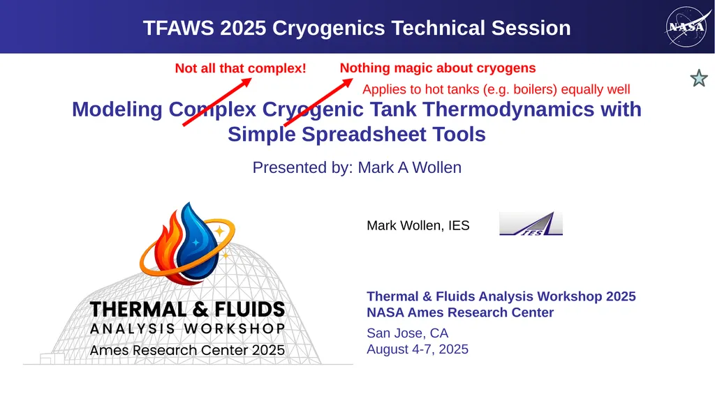
August 4-7, 2025 TFAWS 2025 Cryogenics Technical Session Presented by: Mark A Wollen Not all that complex! Nothing magic about cryogens Applies to hot tanks (e.g. boilers) equally well<br>
NASA Ames Research Center
San Jose, CA
August 4-7, 2025 TFAWS 2025 Cryogenics Technical Session Presented by: Mark A Wollen Not all that complex! Nothing magic about cryogens Applies to hot tanks (e.g. boilers) equally well<br>
03
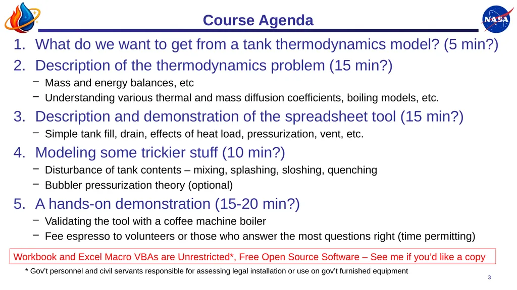
Course Agenda What do we want to get from a tank thermodynamics model? (5 min?)
Description of the thermodynamics problem (15 min?)
Mass and energy balances, etc
Understanding various thermal and mass diffusion coefficients, boiling models, etc.
Description and demonstration of the spreadsheet tool (15 min?)
Simple tank fill, drain, effects of heat load, pressurization, vent, etc.
Modeling some trickier stuff (10 min?)
Disturbance of tank contents – mixing, splashing, sloshing, quenching
Bubbler pressurization theory (optional)
A hands-on demonstration (15-20 min?)
Validating the tool with a coffee machine boiler
Fee espresso to volunteers or those who answer the most questions right (time permitting) 3 Workbook and Excel Macro VBAs are Unrestricted*, Free Open Source Software – See me if you’d like a copy * Gov’t personnel and civil servants responsible for assessing legal installation or use on gov’t furnished equipment<br>
Description of the thermodynamics problem (15 min?)
Mass and energy balances, etc
Understanding various thermal and mass diffusion coefficients, boiling models, etc.
Description and demonstration of the spreadsheet tool (15 min?)
Simple tank fill, drain, effects of heat load, pressurization, vent, etc.
Modeling some trickier stuff (10 min?)
Disturbance of tank contents – mixing, splashing, sloshing, quenching
Bubbler pressurization theory (optional)
A hands-on demonstration (15-20 min?)
Validating the tool with a coffee machine boiler
Fee espresso to volunteers or those who answer the most questions right (time permitting) 3 Workbook and Excel Macro VBAs are Unrestricted*, Free Open Source Software – See me if you’d like a copy * Gov’t personnel and civil servants responsible for assessing legal installation or use on gov’t furnished equipment<br>
04
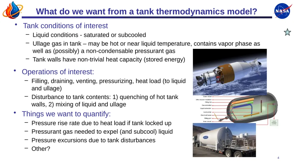
What do we want from a tank thermodynamics model? Tank conditions of interest
Liquid conditions - saturated or subcooled
Ullage gas in tank – may be hot or near liquid temperature, contains vapor phase as well as (possibly) a non-condensable pressurant gas
Tank walls have non-trivial heat capacity (stored energy) 4 Operations of interest:
Filling, draining, venting, pressurizing, heat load (to liquid and ullage)
Disturbance to tank contents: 1) quenching of hot tank walls, 2) mixing of liquid and ullage
Things we want to quantify:
Pressure rise rate due to heat load if tank locked up
Pressurant gas needed to expel (and subcool) liquid
Pressure excursions due to tank disturbances
Other?<br>
Liquid conditions - saturated or subcooled
Ullage gas in tank – may be hot or near liquid temperature, contains vapor phase as well as (possibly) a non-condensable pressurant gas
Tank walls have non-trivial heat capacity (stored energy) 4 Operations of interest:
Filling, draining, venting, pressurizing, heat load (to liquid and ullage)
Disturbance to tank contents: 1) quenching of hot tank walls, 2) mixing of liquid and ullage
Things we want to quantify:
Pressure rise rate due to heat load if tank locked up
Pressurant gas needed to expel (and subcool) liquid
Pressure excursions due to tank disturbances
Other?<br>
05
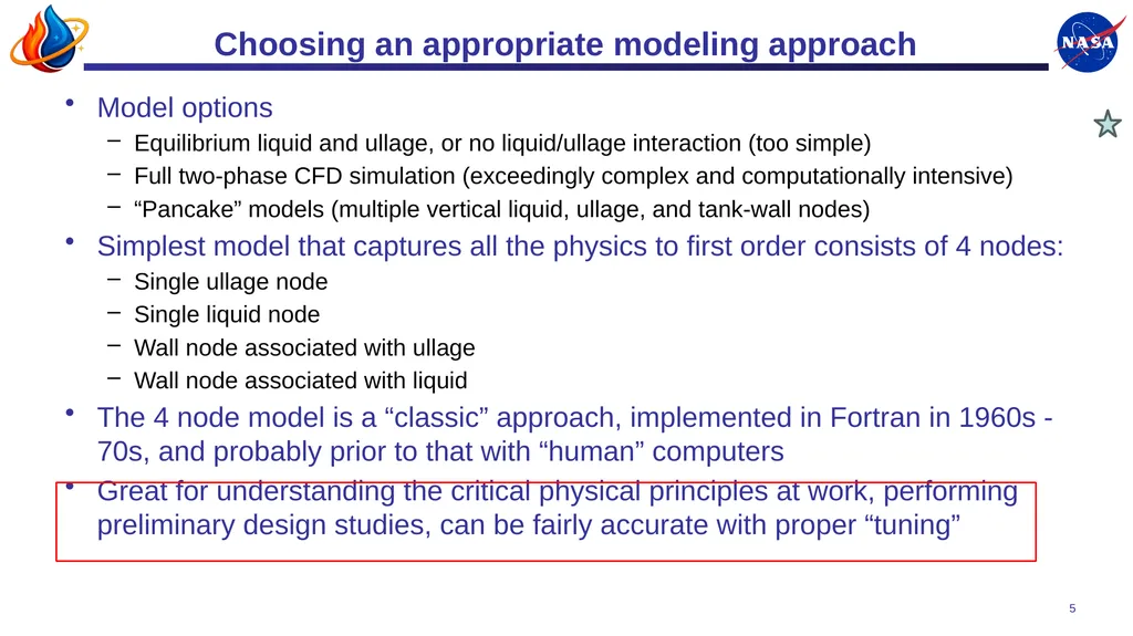
Choosing an appropriate modeling approach Model options
Equilibrium liquid and ullage, or no liquid/ullage interaction (too simple)
Full two-phase CFD simulation (exceedingly complex and computationally intensive)
“Pancake” models (multiple vertical liquid, ullage, and tank-wall nodes)
Simplest model that captures all the physics to first order consists of 4 nodes:
Single ullage node
Single liquid node
Wall node associated with ullage
Wall node associated with liquid
The 4 node model is a “classic” approach, implemented in Fortran in 1960s - 70s, and probably prior to that with “human” computers
Great for understanding the critical physical principles at work, performing preliminary design studies, can be fairly accurate with proper “tuning” 5<br>
Equilibrium liquid and ullage, or no liquid/ullage interaction (too simple)
Full two-phase CFD simulation (exceedingly complex and computationally intensive)
“Pancake” models (multiple vertical liquid, ullage, and tank-wall nodes)
Simplest model that captures all the physics to first order consists of 4 nodes:
Single ullage node
Single liquid node
Wall node associated with ullage
Wall node associated with liquid
The 4 node model is a “classic” approach, implemented in Fortran in 1960s - 70s, and probably prior to that with “human” computers
Great for understanding the critical physical principles at work, performing preliminary design studies, can be fairly accurate with proper “tuning” 5<br>
06
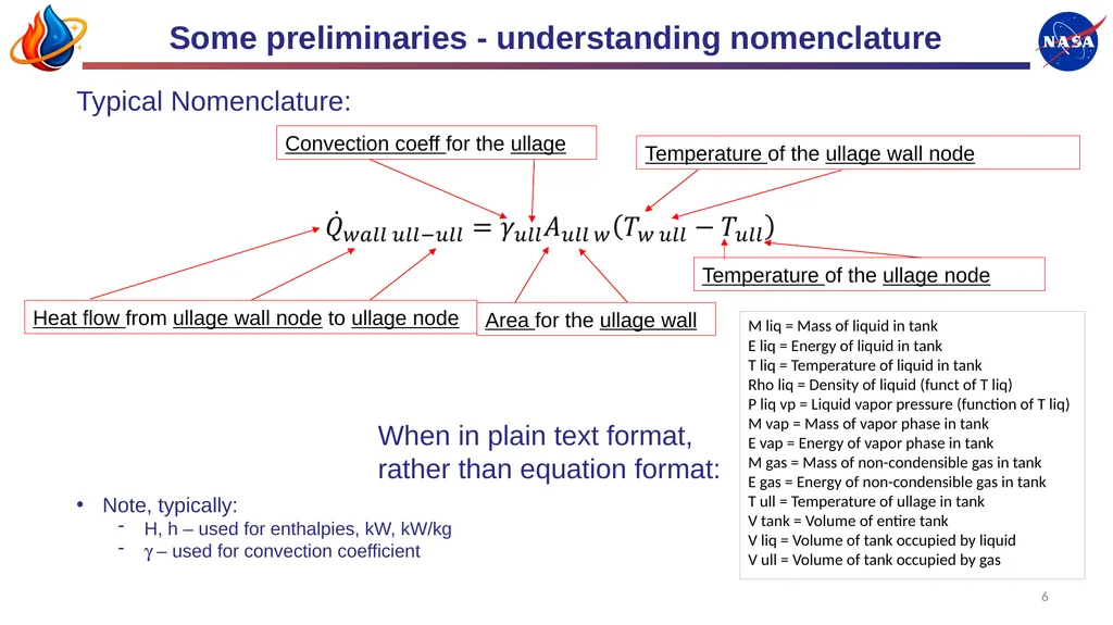
Some preliminaries - understanding nomenclature M liq = Mass of liquid in tank
E liq = Energy of liquid in tank
T liq = Temperature of liquid in tank
Rho liq = Density of liquid (funct of T liq)
P liq vp = Liquid vapor pressure (function of T liq)
M vap = Mass of vapor phase in tank
E vap = Energy of vapor phase in tank
M gas = Mass of non-condensible gas in tank
E gas = Energy of non-condensible gas in tank
T ull = Temperature of ullage in tank
V tank = Volume of entire tank
V liq = Volume of tank occupied by liquid
V ull = Volume of tank occupied by gas Typical Nomenclature: 6 Heat flow from ullage wall node to ullage node Convection coeff for the ullage Area for the ullage wall Temperature of the ullage wall node Temperature of the ullage node When in plain text format, rather than equation format: Note, typically:
H, h – used for enthalpies, kW, kW/kg
g – used for convection coefficient<br>
E liq = Energy of liquid in tank
T liq = Temperature of liquid in tank
Rho liq = Density of liquid (funct of T liq)
P liq vp = Liquid vapor pressure (function of T liq)
M vap = Mass of vapor phase in tank
E vap = Energy of vapor phase in tank
M gas = Mass of non-condensible gas in tank
E gas = Energy of non-condensible gas in tank
T ull = Temperature of ullage in tank
V tank = Volume of entire tank
V liq = Volume of tank occupied by liquid
V ull = Volume of tank occupied by gas Typical Nomenclature: 6 Heat flow from ullage wall node to ullage node Convection coeff for the ullage Area for the ullage wall Temperature of the ullage wall node Temperature of the ullage node When in plain text format, rather than equation format: Note, typically:
H, h – used for enthalpies, kW, kW/kg
g – used for convection coefficient<br>
07
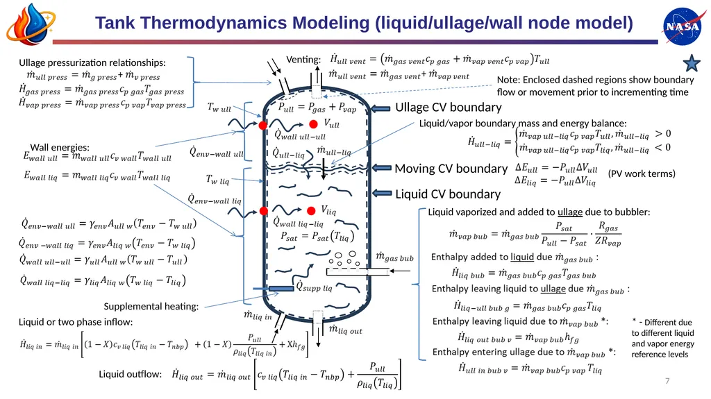
Tank Thermodynamics Modeling (liquid/ullage/wall node model) Ullage CV boundary Liquid CV boundary Moving CV boundary Note: Enclosed dashed regions show boundary flow or movement prior to incrementing time Liquid vaporized and added to ullage due to bubbler: * - Different due to different liquid and vapor energy reference levels Venting: Ullage pressurization relationships: Liquid or two phase inflow: Liquid outflow: Liquid/vapor boundary mass and energy balance: Supplemental heating: Wall energies: (PV work terms) 7<br>
08
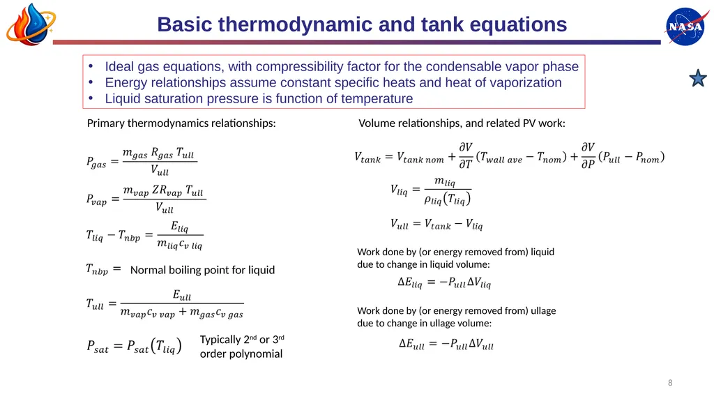
Basic thermodynamic and tank equations Work done by (or energy removed from) liquid due to change in liquid volume: Work done by (or energy removed from) ullage due to change in ullage volume: Volume relationships, and related PV work: Primary thermodynamics relationships: Normal boiling point for liquid Ideal gas equations, with compressibility factor for the condensable vapor phase
Energy relationships assume constant specific heats and heat of vaporization
Liquid saturation pressure is function of temperature 8 Typically 2nd or 3rd order polynomial<br>
Energy relationships assume constant specific heats and heat of vaporization
Liquid saturation pressure is function of temperature 8 Typically 2nd or 3rd order polynomial<br>
09
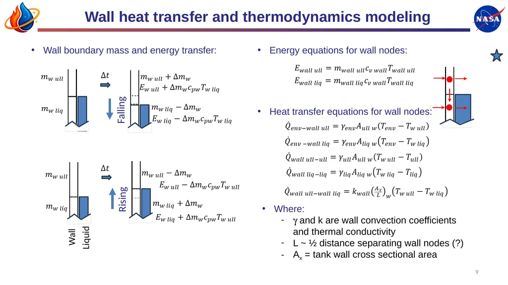
Wall heat transfer and thermodynamics modeling Falling Rising Wall boundary mass and energy transfer: Energy equations for wall nodes: Heat transfer equations for wall nodes: Where:
g and k are wall convection coefficients and thermal conductivity
L ~ ½ distance separating wall nodes (?)
Ax = tank wall cross sectional area 9 Wall Liquid<br>
g and k are wall convection coefficients and thermal conductivity
L ~ ½ distance separating wall nodes (?)
Ax = tank wall cross sectional area 9 Wall Liquid<br>
10
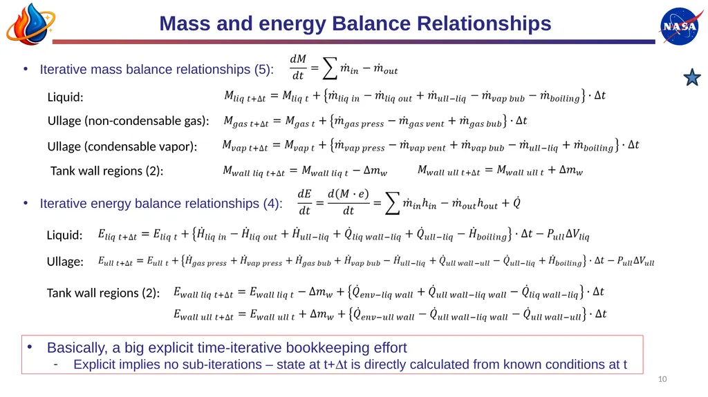
Mass and energy Balance Relationships Iterative mass balance relationships (5): Iterative energy balance relationships (4): Liquid: Ullage (non-condensable gas): Ullage (condensable vapor): Liquid: Ullage: Tank wall regions (2): Tank wall regions (2): Basically, a big explicit time-iterative bookkeeping effort
Explicit implies no sub-iterations – state at t+Dt is directly calculated from known conditions at t 10<br>
Explicit implies no sub-iterations – state at t+Dt is directly calculated from known conditions at t 10<br>
11
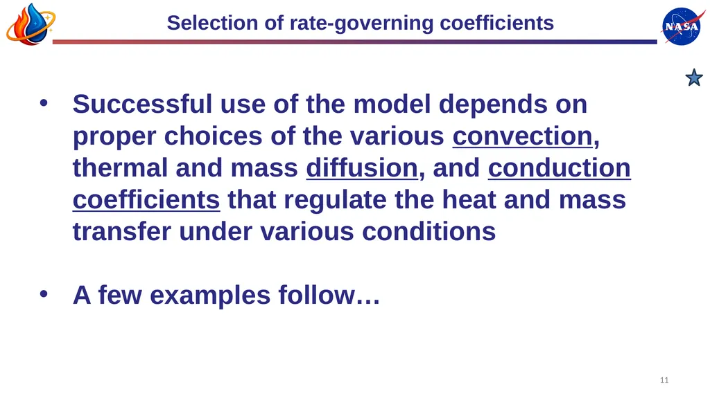
Selection of rate-governing coefficients Successful use of the model depends on proper choices of the various convection, thermal and mass diffusion, and conduction coefficients that regulate the heat and mass transfer under various conditions
A few examples follow… 11<br>
A few examples follow… 11<br>
12
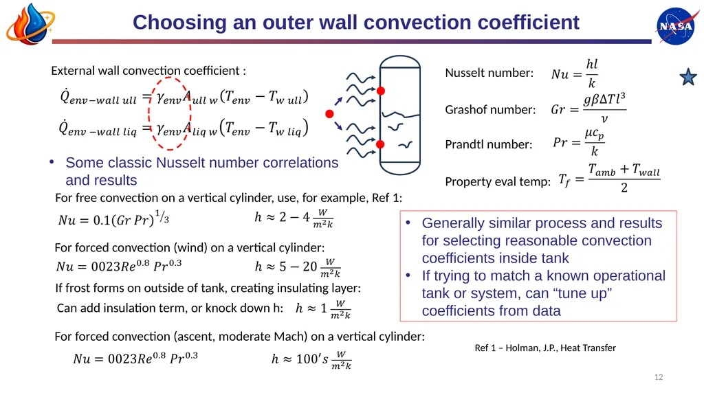
Choosing an outer wall convection coefficient External wall convection coefficient : For free convection on a vertical cylinder, use, for example, Ref 1: Nusselt number: Grashof number: Prandtl number: Property eval temp: For forced convection (wind) on a vertical cylinder: For forced convection (ascent, moderate Mach) on a vertical cylinder: If frost forms on outside of tank, creating insulating layer: Can add insulation term, or knock down h: Some classic Nusselt number correlations and results 12 Generally similar process and results for selecting reasonable convection coefficients inside tank
If trying to match a known operational tank or system, can “tune up” coefficients from data Ref 1 – Holman, J.P., Heat Transfer<br>
If trying to match a known operational tank or system, can “tune up” coefficients from data Ref 1 – Holman, J.P., Heat Transfer<br>
13
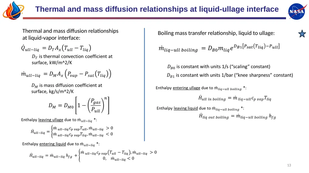
Thermal and mass diffusion relationships at liquid-ullage interface Thermal and mass diffusion relationships at liquid-vapor interface: Boiling mass transfer relationship, liquid to ullage: 13<br>
14
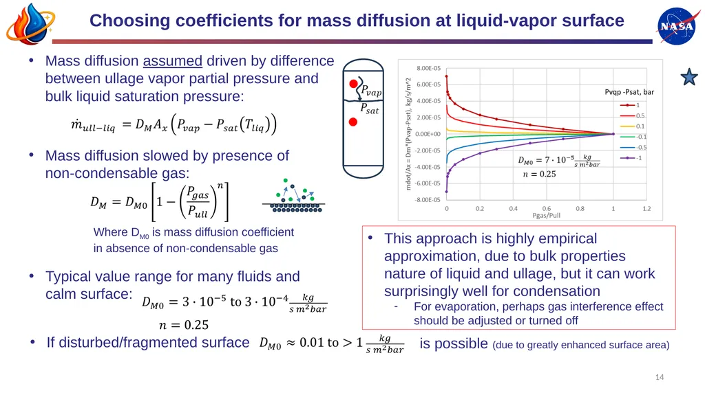
Choosing coefficients for mass diffusion at liquid-vapor surface Where DM0 is mass diffusion coefficient in absence of non-condensable gas 14 This approach is highly empirical approximation, due to bulk properties nature of liquid and ullage, but it can work surprisingly well for condensation
For evaporation, perhaps gas interference effect should be adjusted or turned off Mass diffusion slowed by presence of non-condensable gas: Mass diffusion assumed driven by difference between ullage vapor partial pressure and bulk liquid saturation pressure: Typical value range for many fluids and calm surface: If disturbed/fragmented surface is possible (due to greatly enhanced surface area)<br>
For evaporation, perhaps gas interference effect should be adjusted or turned off Mass diffusion slowed by presence of non-condensable gas: Mass diffusion assumed driven by difference between ullage vapor partial pressure and bulk liquid saturation pressure: Typical value range for many fluids and calm surface: If disturbed/fragmented surface is possible (due to greatly enhanced surface area)<br>
15
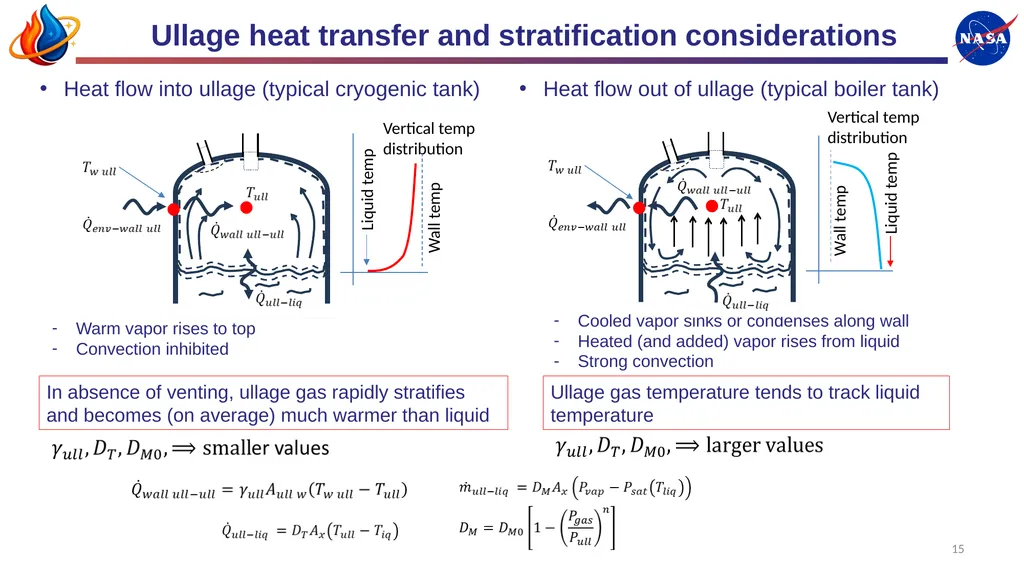
Ullage heat transfer and stratification considerations 15 Heat flow into ullage (typical cryogenic tank) Warm vapor rises to top
Convection inhibited Cooled vapor sinks or condenses along wall
Heated (and added) vapor rises from liquid
Strong convection Heat flow out of ullage (typical boiler tank) In absence of venting, ullage gas rapidly stratifies and becomes (on average) much warmer than liquid Ullage gas temperature tends to track liquid temperature Liquid temp Liquid temp Vertical temp distribution Vertical temp distribution Wall temp Wall temp<br>
Convection inhibited Cooled vapor sinks or condenses along wall
Heated (and added) vapor rises from liquid
Strong convection Heat flow out of ullage (typical boiler tank) In absence of venting, ullage gas rapidly stratifies and becomes (on average) much warmer than liquid Ullage gas temperature tends to track liquid temperature Liquid temp Liquid temp Vertical temp distribution Vertical temp distribution Wall temp Wall temp<br>
16
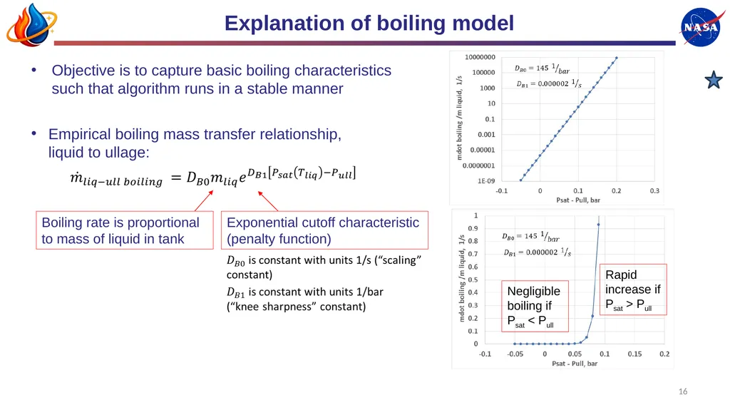
Explanation of boiling model 16 Exponential cutoff characteristic (penalty function) Empirical boiling mass transfer relationship, liquid to ullage: Objective is to capture basic boiling characteristics such that algorithm runs in a stable manner Boiling rate is proportional to mass of liquid in tank Negligible boiling if Psat < Pull Rapid increase if Psat > Pull<br>
17
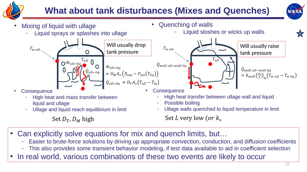
What about tank disturbances (Mixes and Quenches) 17 Mixing of liquid with ullage
Liquid sprays or splashes into ullage Consequence
High heat and mass transfer between liquid and ullage
Ullage and liquid reach equilibrium in limit Quenching of walls
Liquid sloshes or wicks up walls Can explicitly solve equations for mix and quench limits, but…
Easier to brute-force solutions by driving up appropriate convection, conduction, and diffusion coefficients
This also provides some transient behavior modeling, if test data available to aid in coefficient selection
In real world, various combinations of these two events are likely to occur Consequence
High heat transfer between ullage wall and liquid
Possible boiling
Ullage walls quenched to liquid temperature in limit Will usually drop tank pressure Will usually raise tank pressure<br>
Liquid sprays or splashes into ullage Consequence
High heat and mass transfer between liquid and ullage
Ullage and liquid reach equilibrium in limit Quenching of walls
Liquid sloshes or wicks up walls Can explicitly solve equations for mix and quench limits, but…
Easier to brute-force solutions by driving up appropriate convection, conduction, and diffusion coefficients
This also provides some transient behavior modeling, if test data available to aid in coefficient selection
In real world, various combinations of these two events are likely to occur Consequence
High heat transfer between ullage wall and liquid
Possible boiling
Ullage walls quenched to liquid temperature in limit Will usually drop tank pressure Will usually raise tank pressure<br>
18
18 Description of spreadsheet tools Implementation of 4 node model in spreadsheets with VBA macros<br>
19
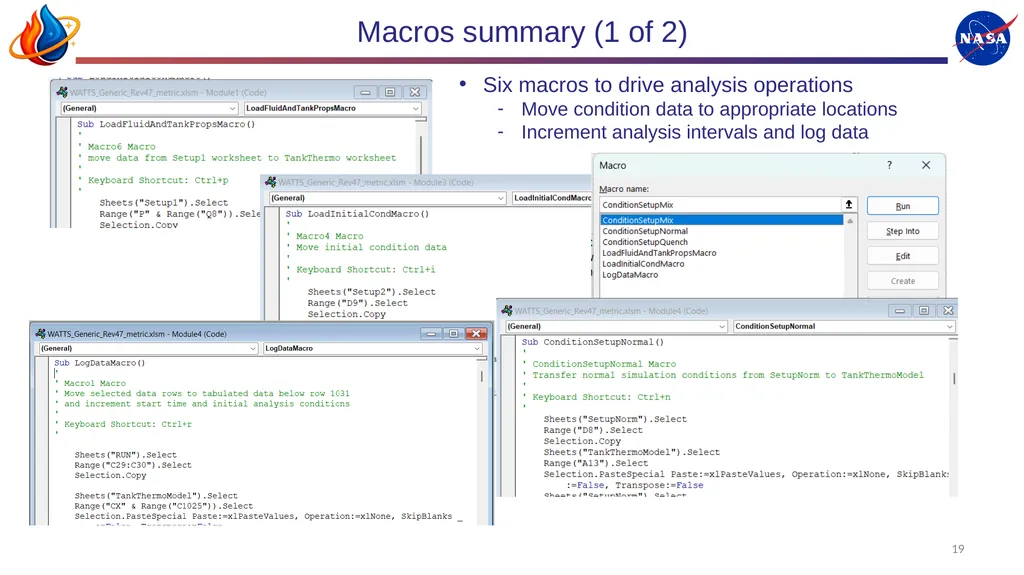
Macros summary (1 of 2) 19 Six macros to drive analysis operations
Move condition data to appropriate locations
Increment analysis intervals and log data<br>
Move condition data to appropriate locations
Increment analysis intervals and log data<br>
20
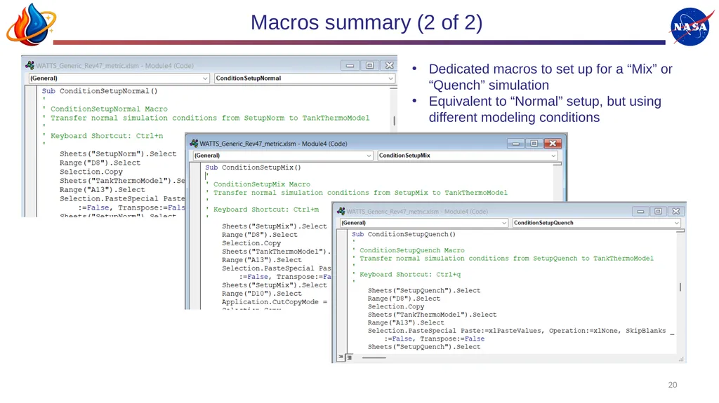
20 Macros summary (2 of 2) Dedicated macros to set up for a “Mix” or “Quench” simulation
Equivalent to “Normal” setup, but using different modeling conditions<br>
Equivalent to “Normal” setup, but using different modeling conditions<br>
21
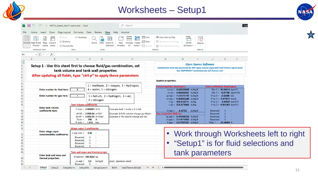
21 Worksheets – Setup1 Work through Worksheets left to right
“Setup1” is for fluid selections and tank parameters<br>
“Setup1” is for fluid selections and tank parameters<br>
22
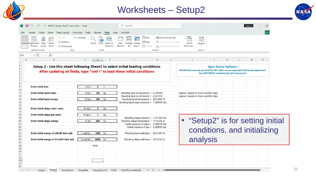
22 Worksheets – Setup2 “Setup2” is for setting initial conditions, and initializing analysis<br>
23
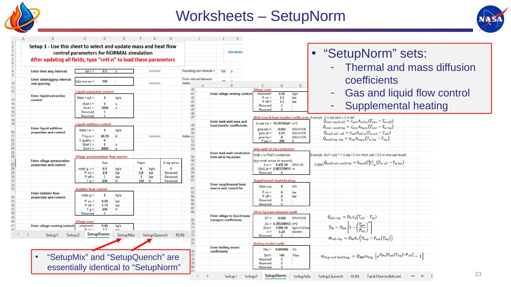
23 Worksheets – SetupNorm “SetupNorm” sets:
Thermal and mass diffusion coefficients
Gas and liquid flow control
Supplemental heating “SetupMix” and “SetupQuench” are essentially identical to “SetupNorm”<br>
Thermal and mass diffusion coefficients
Gas and liquid flow control
Supplemental heating “SetupMix” and “SetupQuench” are essentially identical to “SetupNorm”<br>
24
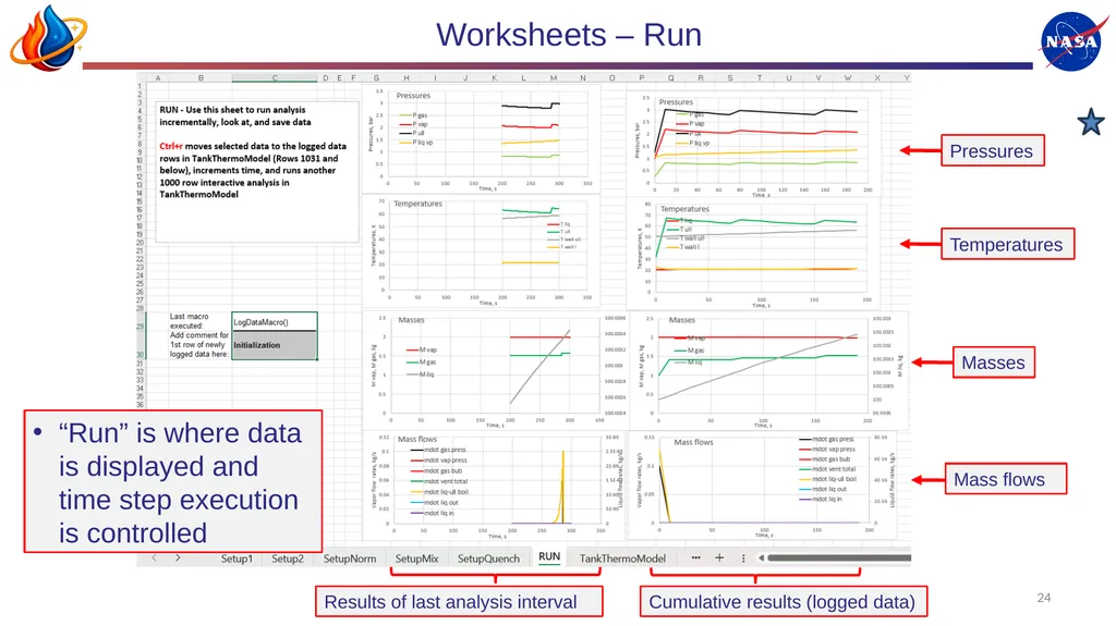
24 Worksheets – Run “Run” is where data is displayed and time step execution is controlled Results of last analysis interval Cumulative results (logged data) Pressures Temperatures Masses Mass flows<br>
25
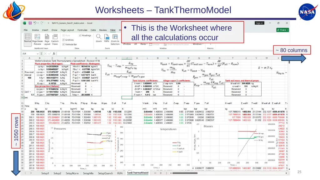
25 Worksheets – TankThermoModel This is the Worksheet where all the calculations occur ~ 80 columns ~ 1050 rows<br>
26
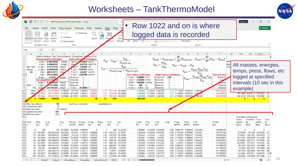
26 Worksheets – TankThermoModel Row 1022 and on is where logged data is recorded All masses, energies, temps, press, flows, etc logged at specified intervals (10 sec in this example)<br>
27
Analysis demonstration (optional) 27 Perform real time analysis demonstration of tank loading, pressurization, outflow with heating (i.e., ascent), and mix/quench disturbance for a hydrogen tank<br>
28
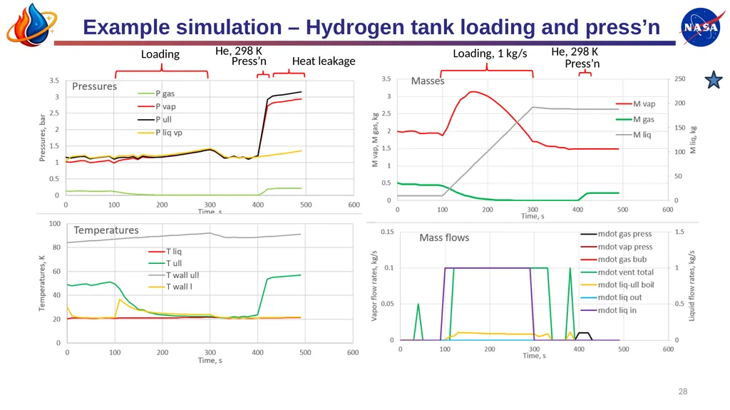
Example simulation – Hydrogen tank loading and press’n 28 Loading Press’n Loading, 1 kg/s Press’n He, 298 K Heat leakage He, 298 K<br>
29
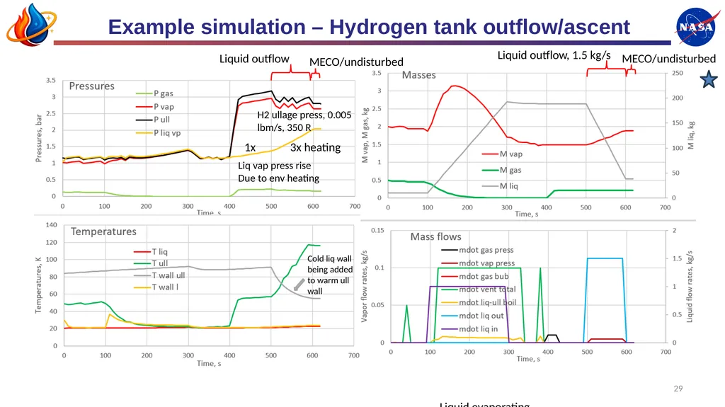
Example simulation – Hydrogen tank outflow/ascent 29 Liquid evaporating into ullage as temperature rises Cold liq wall being added to warm ull wall Liquid outflow, 1.5 kg/s MECO/undisturbed Liquid outflow MECO/undisturbed H2 ullage press, 0.005 lbm/s, 350 R Liq vap press rise
Due to env heating 1x 3x heating<br>
Due to env heating 1x 3x heating<br>
30
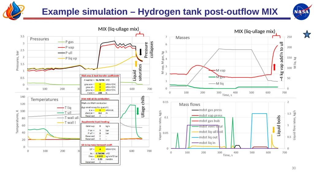
Example simulation – Hydrogen tank post-outflow MIX 30 Liquid saturates MIX (liq-ullage mix) MIX (liq-ullage mix) Ullage chills Liquid boils ~4 kg vap add’n to ull Pressure collapses<br>
31
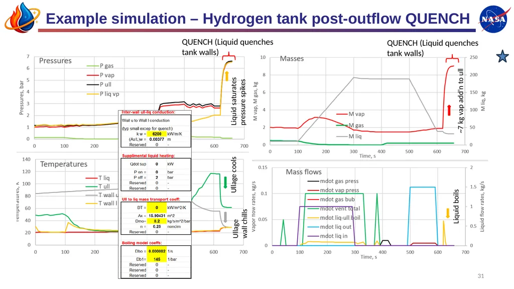
Example simulation – Hydrogen tank post-outflow QUENCH 31 Liquid saturates pressure spikes QUENCH (Liquid quenches tank walls) Ullage cools Liquid boils ~7 kg vap add’n to ull QUENCH (Liquid quenches tank walls) Ullage wall chills<br>
32
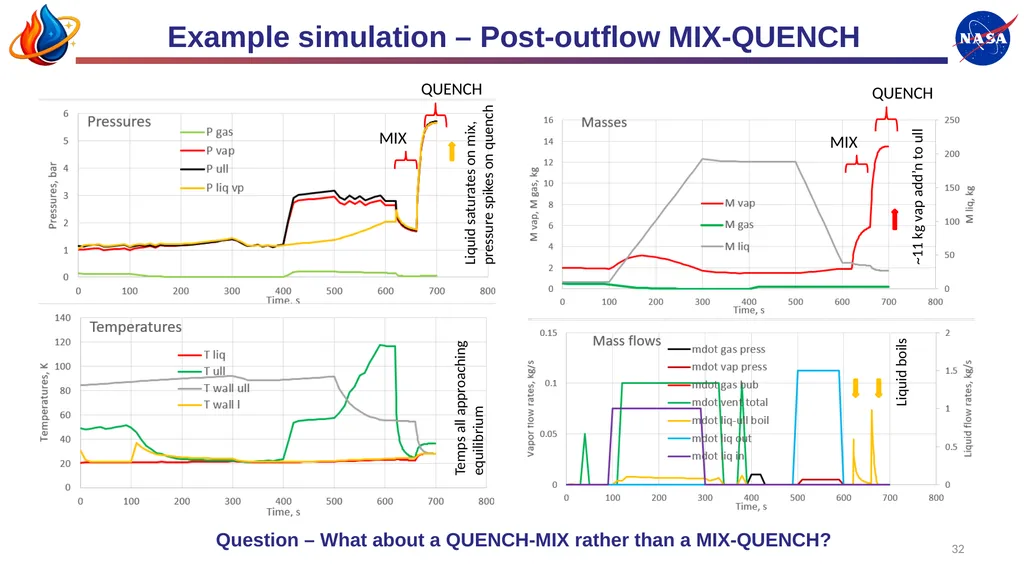
Example simulation – Post-outflow MIX-QUENCH 32 Liquid saturates on mix, pressure spikes on quench MIX Liquid boils ~11 kg vap add’n to ull QUENCH Temps all approaching equilibrium MIX QUENCH Question – What about a QUENCH-MIX rather than a MIX-QUENCH?<br>
33
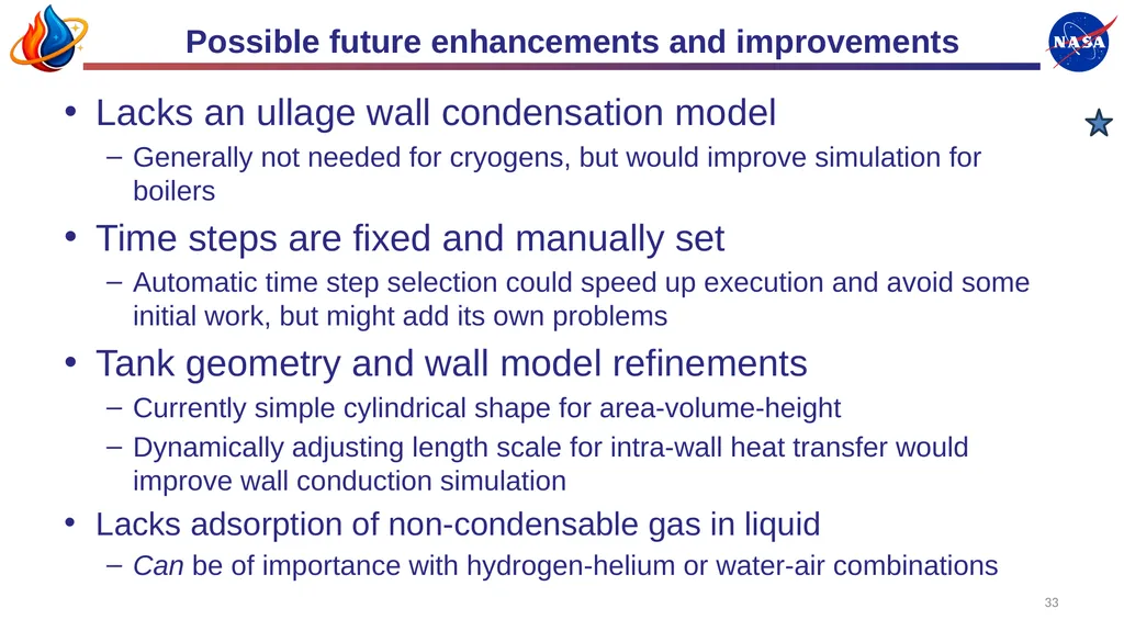
Possible future enhancements and improvements 33 Lacks an ullage wall condensation model
Generally not needed for cryogens, but would improve simulation for boilers
Time steps are fixed and manually set
Automatic time step selection could speed up execution and avoid some initial work, but might add its own problems
Tank geometry and wall model refinements
Currently simple cylindrical shape for area-volume-height
Dynamically adjusting length scale for intra-wall heat transfer would improve wall conduction simulation
Lacks adsorption of non-condensable gas in liquid
Can be of importance with hydrogen-helium or water-air combinations<br>
Generally not needed for cryogens, but would improve simulation for boilers
Time steps are fixed and manually set
Automatic time step selection could speed up execution and avoid some initial work, but might add its own problems
Tank geometry and wall model refinements
Currently simple cylindrical shape for area-volume-height
Dynamically adjusting length scale for intra-wall heat transfer would improve wall conduction simulation
Lacks adsorption of non-condensable gas in liquid
Can be of importance with hydrogen-helium or water-air combinations<br>
34
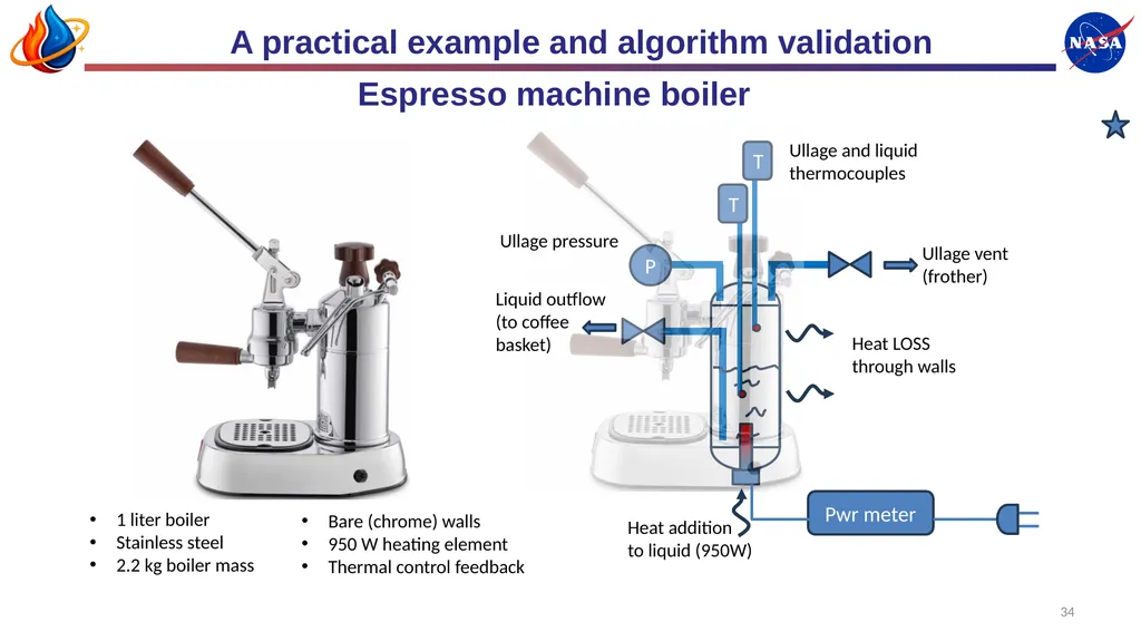
A practical example and algorithm validation 34 T T P Pwr meter Heat LOSS through walls Heat addition
to liquid (950W) Ullage vent (frother) Liquid outflow (to coffee basket) Ullage and liquid thermocouples Ullage pressure Espresso machine boiler 1 liter boiler
Stainless steel
2.2 kg boiler mass Bare (chrome) walls
950 W heating element
Thermal control feedback<br>
to liquid (950W) Ullage vent (frother) Liquid outflow (to coffee basket) Ullage and liquid thermocouples Ullage pressure Espresso machine boiler 1 liter boiler
Stainless steel
2.2 kg boiler mass Bare (chrome) walls
950 W heating element
Thermal control feedback<br>
35
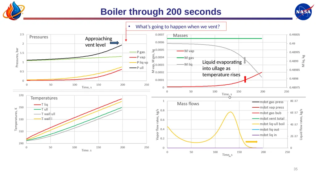
Boiler through 200 seconds 35 Liquid evaporating into ullage as temperature rises Approaching vent level What’s going to happen when we vent?<br>
36
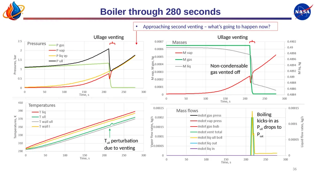
Boiler through 280 seconds 36 Ullage venting Ullage venting Non-condensable gas vented off Boiling kicks-in as Pull drops to Psat Tull perturbation due to venting Approaching second venting – what’s going to happen now?<br>
37
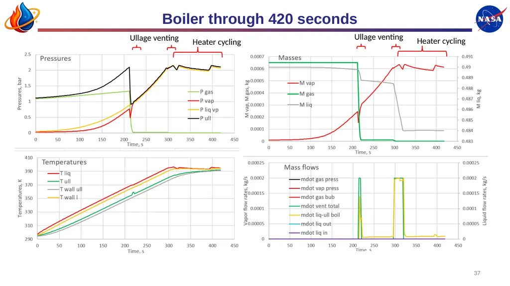
Boiler through 420 seconds 37 Heater cycling Ullage venting Heater cycling Ullage venting<br>
38
End of presentation 38 Questions?
Time for coffee break?<br>
Time for coffee break?<br>