
MEKPCO FLARE NETWORK DESIGN ASPEN FLARENET Flare
JO
Published · 112 slides · 0 views

1 / 1










Description
MEKPCO FLARE NETWORK DESIGN ASPEN FLARENET Flare System Design Procedure In order to design a flare package , the following procedure is taken : Determination of worst case scenarios Flare network line sizing using Aspen flarenet and
Related Topics
Share
Embed code
Download this presentation From Below
"MEKPCO FLARE NETWORK DESIGN ASPEN FLARENET Flare" is the property of its rightful owner. Permission is granted to download and print the materials on this website for personal, non-commercial use only, and to display it on your personal computer provided you do not modify the materials and that you retain all copyright notices contained in the materials. By downloading content from our website, you accept the terms of this agreement.
Presentation Transcript
01
MEKPCO FLARE NETWORK DESIGN
ASPEN FLARENET<br>
ASPEN FLARENET<br>
02
Flare System Design Procedure
In order to design a flare package , the following procedure is taken :
Determination of worst case scenarios
Flare network line sizing using Aspen flarenet and API-527
Flare K.O.D sizing using API-527 excel sheet
Stack height and diameter calculation by API-527<br>
In order to design a flare package , the following procedure is taken :
Determination of worst case scenarios
Flare network line sizing using Aspen flarenet and API-527
Flare K.O.D sizing using API-527 excel sheet
Stack height and diameter calculation by API-527<br>
03
System Description
The overall Flare system consists of three parts:
The first part is made of flare network and K.O.D inside MEKPCO plant. The second part is made of
flare main pipes between the tie-in point of the plant and flare area at the northeast. The third part
consists of flare stack package which will be located on the north mountain. The stack will be located at
X:652388 , Y:3051685 , Z:135 .
2. The flare main header approximate length is considered 2715 for hydraulic analysis implementation,
including the flare piping length 305m between the starting point and the tie-in point in methanol
plant and the flare piping length 2410 between the tie-in point and the actual flare site.
3. For the flare piping routing , one stress expansion loop is set at about 60 m distance , about 27 stress
expansion loops between the tie-in point and the flare stack.<br>
The overall Flare system consists of three parts:
The first part is made of flare network and K.O.D inside MEKPCO plant. The second part is made of
flare main pipes between the tie-in point of the plant and flare area at the northeast. The third part
consists of flare stack package which will be located on the north mountain. The stack will be located at
X:652388 , Y:3051685 , Z:135 .
2. The flare main header approximate length is considered 2715 for hydraulic analysis implementation,
including the flare piping length 305m between the starting point and the tie-in point in methanol
plant and the flare piping length 2410 between the tie-in point and the actual flare site.
3. For the flare piping routing , one stress expansion loop is set at about 60 m distance , about 27 stress
expansion loops between the tie-in point and the flare stack.<br>
04
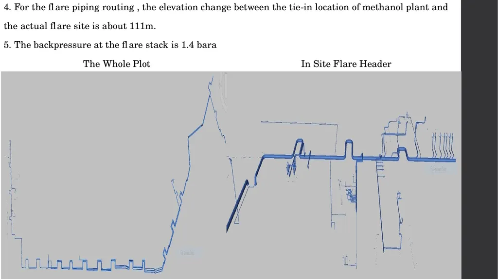
4. For the flare piping routing , the elevation change between the tie-in location of methanol plant and
the actual flare site is about 111m.
5. The backpressure at the flare stack is 1.4 bara
The Whole Plot In Site Flare Header<br>
the actual flare site is about 111m.
5. The backpressure at the flare stack is 1.4 bara
The Whole Plot In Site Flare Header<br>
05
Criteria and Design Basis
The sizing of relief discharge piping can usually be simplified by starting at the system outlet, where
the pressure is known, and working back through the system to verify acceptable backpressure at
each PRD Calculations are performed in a stepwise manner for each pipe segment of constant
diameter.
Several methods for calculating the size of discharge piping have been developed using isothermal or
adiabatic flow equations. Actual flow conditions in relief systems are normally somewhere between
isothermal and adiabatic conditions. For most cases, the slightly more conservative isothermal
equations are recommended.
For both header and tailpipes the Mach number of both 0.1 and 0.5 are taken into account.
The maximum ρν2 for the whole piping should be 150000 kg/m/s2
The sound/ noise level should not exceed the recommended value of 100 DBA<br>
The sizing of relief discharge piping can usually be simplified by starting at the system outlet, where
the pressure is known, and working back through the system to verify acceptable backpressure at
each PRD Calculations are performed in a stepwise manner for each pipe segment of constant
diameter.
Several methods for calculating the size of discharge piping have been developed using isothermal or
adiabatic flow equations. Actual flow conditions in relief systems are normally somewhere between
isothermal and adiabatic conditions. For most cases, the slightly more conservative isothermal
equations are recommended.
For both header and tailpipes the Mach number of both 0.1 and 0.5 are taken into account.
The maximum ρν2 for the whole piping should be 150000 kg/m/s2
The sound/ noise level should not exceed the recommended value of 100 DBA<br>
06
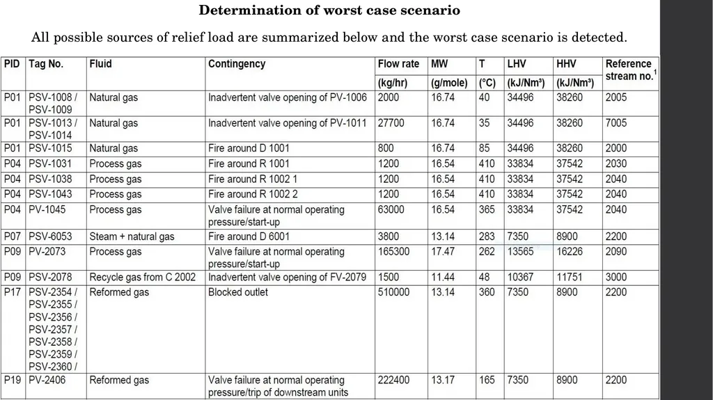
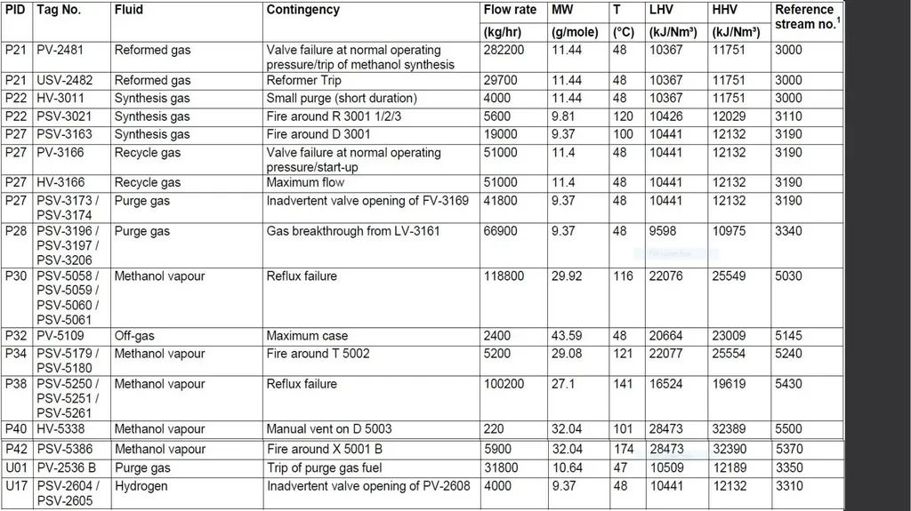
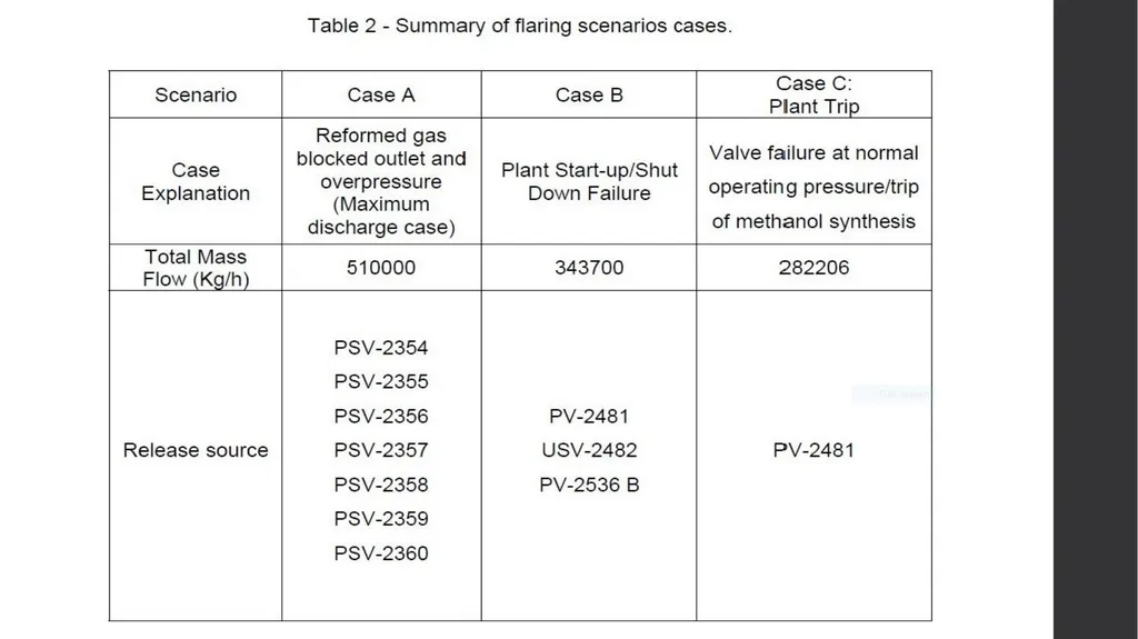
Determination of worst case scenario
All possible sources of relief load are summarized below and the worst case scenario is detected.<br>
All possible sources of relief load are summarized below and the worst case scenario is detected.<br>
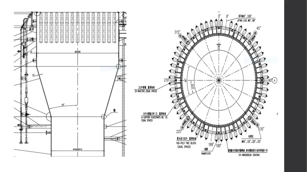
07
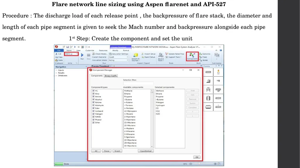
Flare network line sizing using Aspen flarenet and API-527
Procedure : The discharge load of each release point , the backpressure of flare stack, the diameter and
length of each pipe segment is given to seek the Mach number and backpressure alongside each pipe
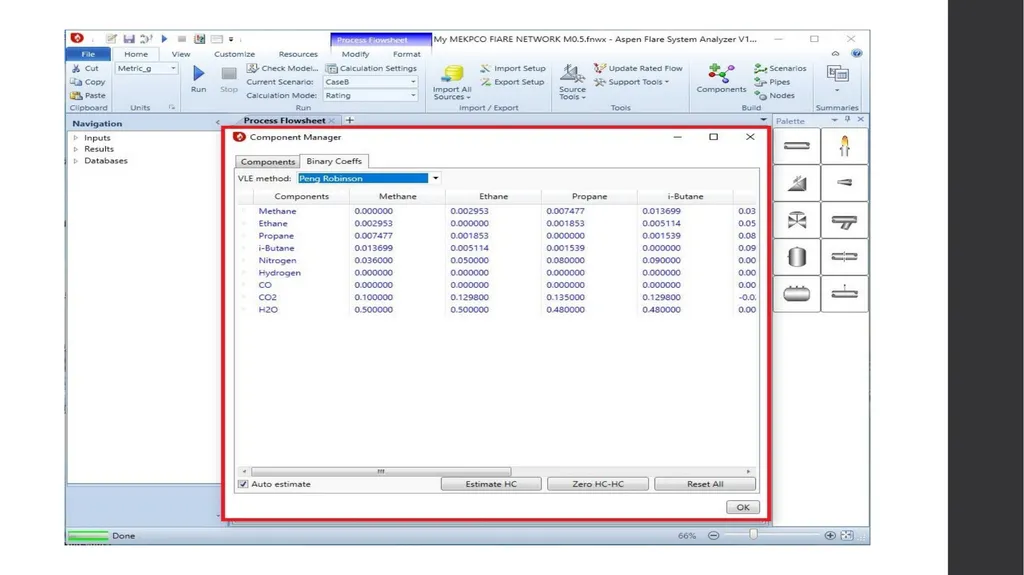
segment. 1st Step: Create the component and set the unit<br>
Procedure : The discharge load of each release point , the backpressure of flare stack, the diameter and
length of each pipe segment is given to seek the Mach number and backpressure alongside each pipe
segment. 1st Step: Create the component and set the unit<br>
08
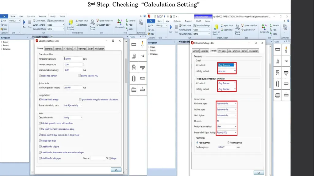
2nd Step: Checking “Calculation Setting”<br>
09
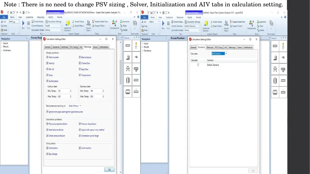
Note : There is no need to change PSV sizing , Solver, Initialization and AIV tabs in calculation setting.<br>
10
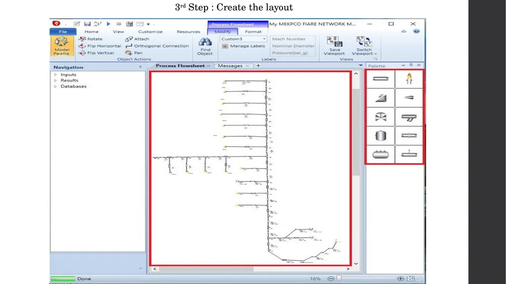
3rd Step : Create the layout<br>
11
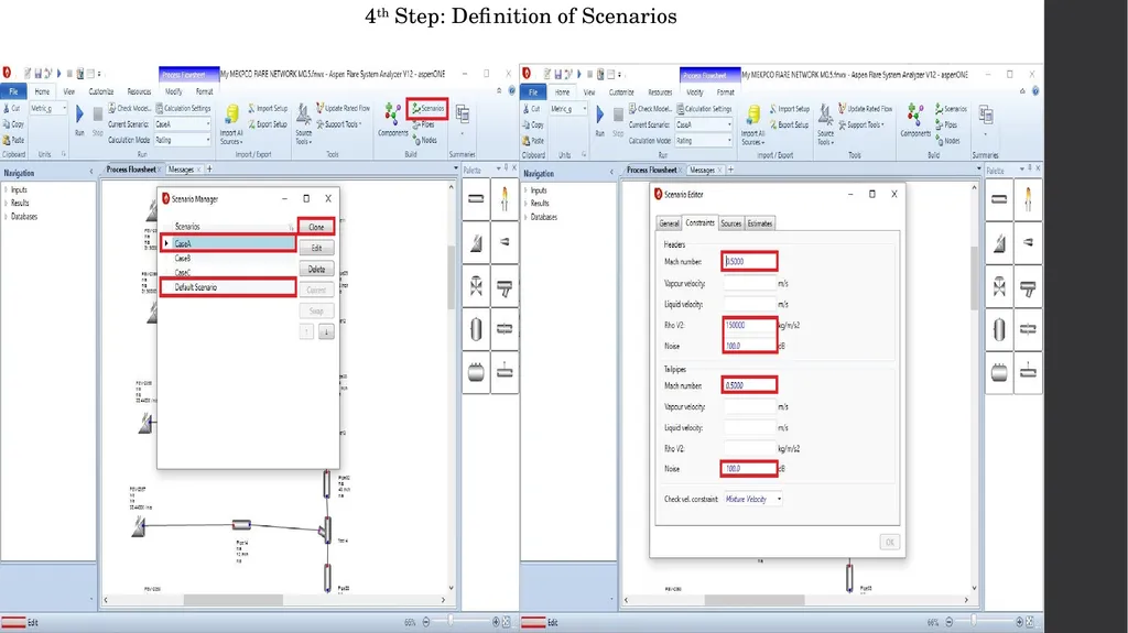
4th Step: Definition of Scenarios<br>
12
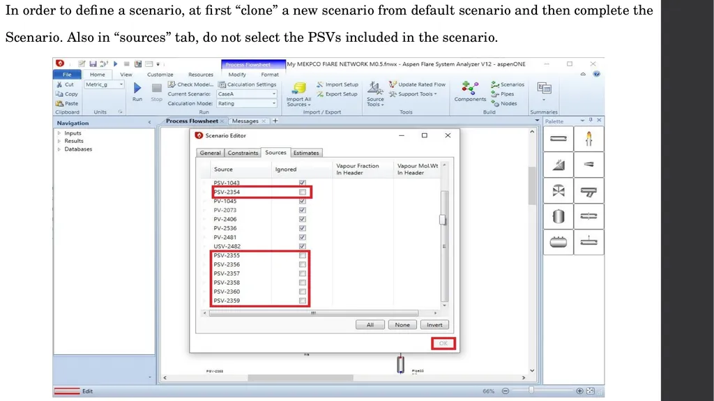
In order to define a scenario, at first “clone” a new scenario from default scenario and then complete the
Scenario. Also in “sources” tab, do not select the PSVs included in the scenario.<br>
Scenario. Also in “sources” tab, do not select the PSVs included in the scenario.<br>
13
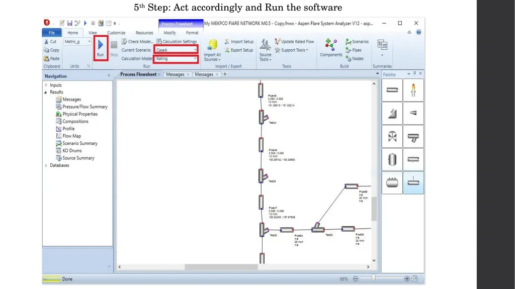
5th Step: Act accordingly and Run the software<br>
14
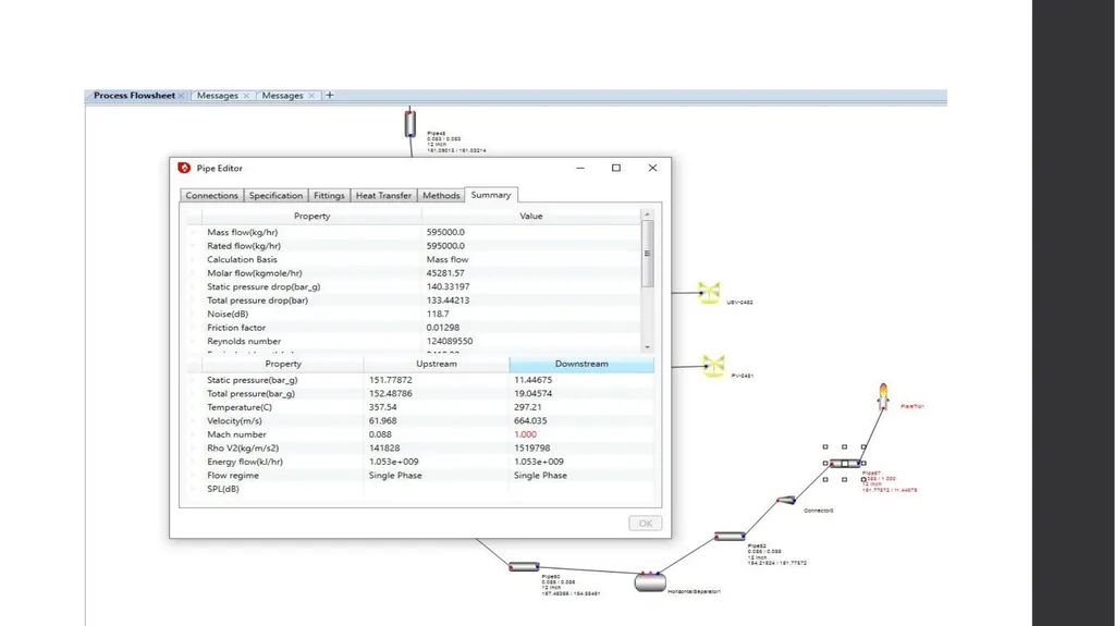
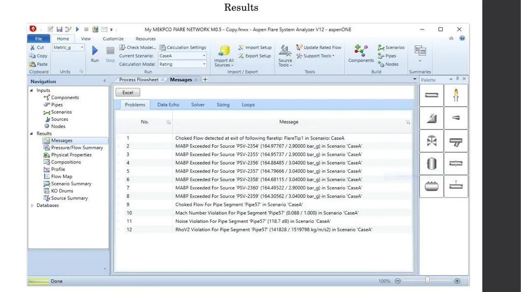
Results<br>
15
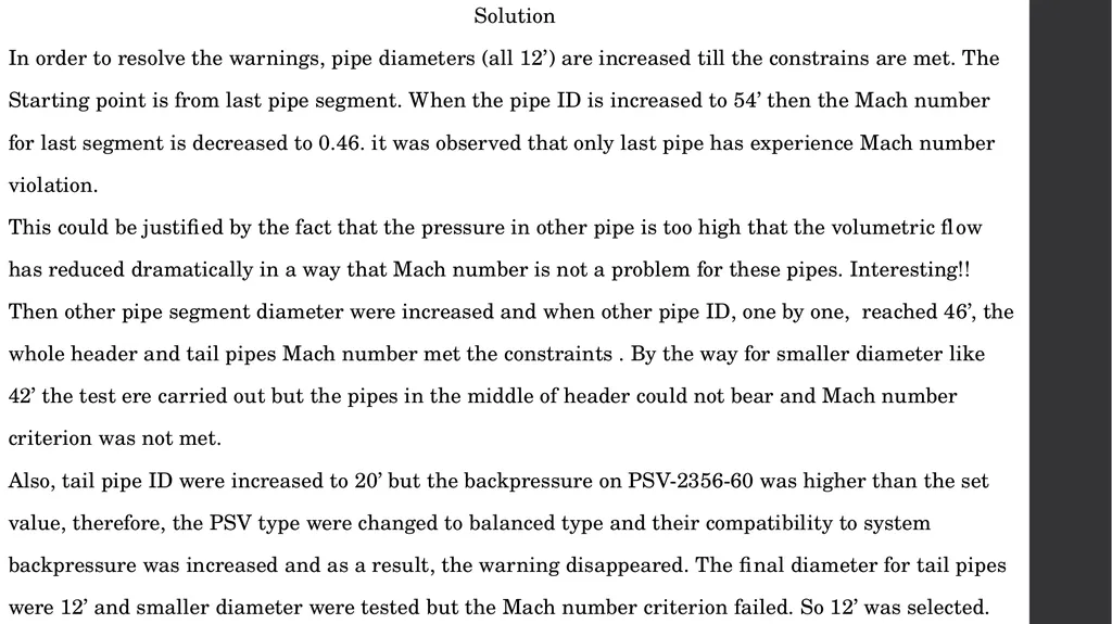
Solution
In order to resolve the warnings, pipe diameters (all 12’) are increased till the constrains are met. The
Starting point is from last pipe segment. When the pipe ID is increased to 54’ then the Mach number
for last segment is decreased to 0.46. it was observed that only last pipe has experience Mach number
violation.
This could be justified by the fact that the pressure in other pipe is too high that the volumetric flow
has reduced dramatically in a way that Mach number is not a problem for these pipes. Interesting!!
Then other pipe segment diameter were increased and when other pipe ID, one by one, reached 46’, the
whole header and tail pipes Mach number met the constraints . By the way for smaller diameter like
42’ the test ere carried out but the pipes in the middle of header could not bear and Mach number
criterion was not met.
Also, tail pipe ID were increased to 20’ but the backpressure on PSV-2356-60 was higher than the set
value, therefore, the PSV type were changed to balanced type and their compatibility to system
backpressure was increased and as a result, the warning disappeared. The final diameter for tail pipes
were 12’ and smaller diameter were tested but the Mach number criterion failed. So 12’ was selected.<br>
In order to resolve the warnings, pipe diameters (all 12’) are increased till the constrains are met. The
Starting point is from last pipe segment. When the pipe ID is increased to 54’ then the Mach number
for last segment is decreased to 0.46. it was observed that only last pipe has experience Mach number
violation.
This could be justified by the fact that the pressure in other pipe is too high that the volumetric flow
has reduced dramatically in a way that Mach number is not a problem for these pipes. Interesting!!
Then other pipe segment diameter were increased and when other pipe ID, one by one, reached 46’, the
whole header and tail pipes Mach number met the constraints . By the way for smaller diameter like
42’ the test ere carried out but the pipes in the middle of header could not bear and Mach number
criterion was not met.
Also, tail pipe ID were increased to 20’ but the backpressure on PSV-2356-60 was higher than the set
value, therefore, the PSV type were changed to balanced type and their compatibility to system
backpressure was increased and as a result, the warning disappeared. The final diameter for tail pipes
were 12’ and smaller diameter were tested but the Mach number criterion failed. So 12’ was selected.<br>
16
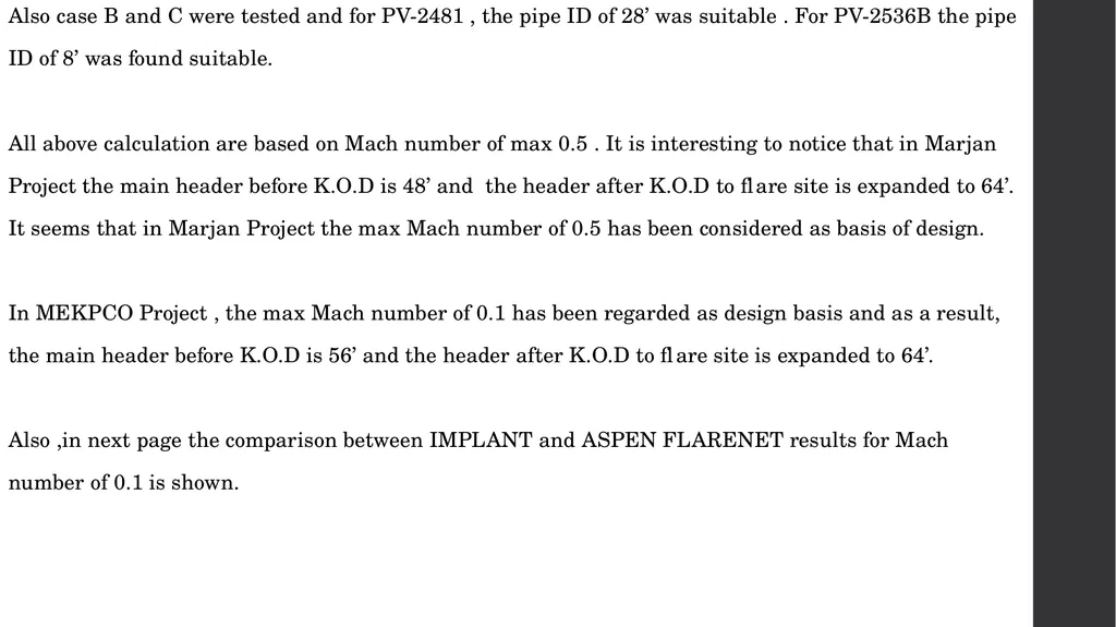
Also case B and C were tested and for PV-2481 , the pipe ID of 28’ was suitable . For PV-2536B the pipe
ID of 8’ was found suitable.
All above calculation are based on Mach number of max 0.5 . It is interesting to notice that in Marjan
Project the main header before K.O.D is 48’ and the header after K.O.D to flare site is expanded to 64’.
It seems that in Marjan Project the max Mach number of 0.5 has been considered as basis of design.
In MEKPCO Project , the max Mach number of 0.1 has been regarded as design basis and as a result,
the main header before K.O.D is 56’ and the header after K.O.D to flare site is expanded to 64’.
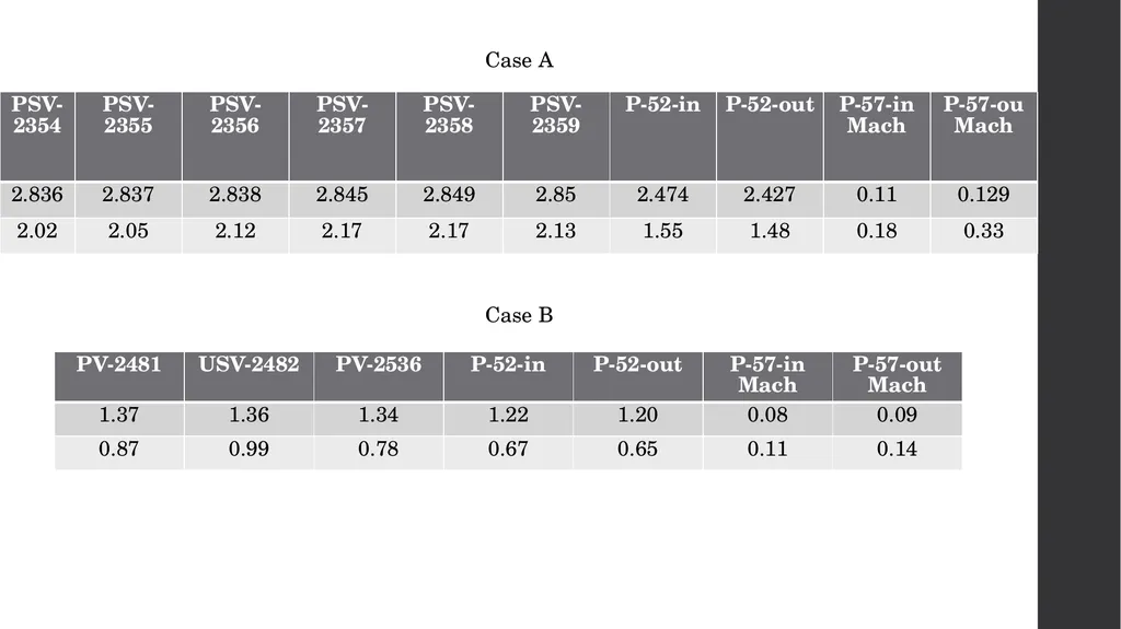
Also ,in next page the comparison between IMPLANT and ASPEN FLARENET results for Mach
number of 0.1 is shown.<br>
ID of 8’ was found suitable.
All above calculation are based on Mach number of max 0.5 . It is interesting to notice that in Marjan
Project the main header before K.O.D is 48’ and the header after K.O.D to flare site is expanded to 64’.
It seems that in Marjan Project the max Mach number of 0.5 has been considered as basis of design.
In MEKPCO Project , the max Mach number of 0.1 has been regarded as design basis and as a result,
the main header before K.O.D is 56’ and the header after K.O.D to flare site is expanded to 64’.
Also ,in next page the comparison between IMPLANT and ASPEN FLARENET results for Mach
number of 0.1 is shown.<br>
17
Case A
Case B<br>
Case B<br>
18
Discussion
It sounds that TCC has set Mach number of 0.1 as the criterion in order to have noise level within
reasonable limits. Furthermore, Implant and Aspen Flarenet results are compared which shows good
Compatibility.
Also the deviation might stem from different composition because in absence of exact composition , MW
Of each source were given to Aspen Flarenet and aspen flarenet estimates the composition.<br>
It sounds that TCC has set Mach number of 0.1 as the criterion in order to have noise level within
reasonable limits. Furthermore, Implant and Aspen Flarenet results are compared which shows good
Compatibility.
Also the deviation might stem from different composition because in absence of exact composition , MW
Of each source were given to Aspen Flarenet and aspen flarenet estimates the composition.<br>
19
Flare K.O.D Sizing
1.Knockout drums are typically located on the main flare line upstream of the flare stack or any liquid
seal. If there are particular pieces of equipment or process units within a plant that release large
amounts of liquid to the flare header, it is desirable to have knockout drums inside the battery limits to
collect these liquids. This reduces the sizing requirements for the main flare knockout drum, as well as
facilitates product recovery.
2. The economics of drum design can influence the choice between a horizontal and a vertical drum. If a
large liquid storage capacity is desired and the vapor flow is high, a horizontal drum is often more
economical. Also, the pressure drop across horizontal drums is generally the lowest of all the designs.
Vertical knockout drums are typically used if the liquid load is low or limited plot space is available.
They are well suited for incorporating into the base of the flare stack.
3. Among disparate configurations proposed in API-527 , a combination of a vertical drum in the base of
the flare stack and a horizontal drum upstream to remove the bulk of the liquid entrained in the vapor
has been selected for MEKPCO. Horizontal drum with the vapor entering one end of the vessel and
exiting at the top of the opposite end (no internal baffling);<br>
1.Knockout drums are typically located on the main flare line upstream of the flare stack or any liquid
seal. If there are particular pieces of equipment or process units within a plant that release large
amounts of liquid to the flare header, it is desirable to have knockout drums inside the battery limits to
collect these liquids. This reduces the sizing requirements for the main flare knockout drum, as well as
facilitates product recovery.
2. The economics of drum design can influence the choice between a horizontal and a vertical drum. If a
large liquid storage capacity is desired and the vapor flow is high, a horizontal drum is often more
economical. Also, the pressure drop across horizontal drums is generally the lowest of all the designs.
Vertical knockout drums are typically used if the liquid load is low or limited plot space is available.
They are well suited for incorporating into the base of the flare stack.
3. Among disparate configurations proposed in API-527 , a combination of a vertical drum in the base of
the flare stack and a horizontal drum upstream to remove the bulk of the liquid entrained in the vapor
has been selected for MEKPCO. Horizontal drum with the vapor entering one end of the vessel and
exiting at the top of the opposite end (no internal baffling);<br>
20
4.A split-entry or split-exit configuration can be used to reduce the drum diameter (but increase the
length) for large flow rates and should be considered if the vessel diameter exceeds 3.66 m (12 ft).
Careful consideration should be given to the hydraulics of split-entry configurations to ensure the flow
is indeed split in the desired proportion. Inlet nozzles should include means such as baffles or long
sweep elbows to prevent re-entrainment of liquid. Long sweep elbows are typically used up to DN 300
(NPS 12) inlet diameter. Baffles are typically used for larger inlet diameters. Neither of these rules has
been applied for MEKPCO application.
5. In general, vapor outlet nozzles should not be fitted with any devices (e.g. deflection plates, baffles,
demister pads, vane packs, etc.), because of the potential for such devices to fail or plug and obstruct
the outlet. Such devices should be used only if the drum is equipped with an alternate outlet nozzle
sized for the drum’s design vapor flow rate and fitted with a rupture disk (or pin-actuated device)
whose burst pressure is selected both to protect the drum against overpressure and to permit proper
operation of the drum and relief system in the event the normal vapor outlet becomes obstructed.<br>
length) for large flow rates and should be considered if the vessel diameter exceeds 3.66 m (12 ft).
Careful consideration should be given to the hydraulics of split-entry configurations to ensure the flow
is indeed split in the desired proportion. Inlet nozzles should include means such as baffles or long
sweep elbows to prevent re-entrainment of liquid. Long sweep elbows are typically used up to DN 300
(NPS 12) inlet diameter. Baffles are typically used for larger inlet diameters. Neither of these rules has
been applied for MEKPCO application.
5. In general, vapor outlet nozzles should not be fitted with any devices (e.g. deflection plates, baffles,
demister pads, vane packs, etc.), because of the potential for such devices to fail or plug and obstruct
the outlet. Such devices should be used only if the drum is equipped with an alternate outlet nozzle
sized for the drum’s design vapor flow rate and fitted with a rupture disk (or pin-actuated device)
whose burst pressure is selected both to protect the drum against overpressure and to permit proper
operation of the drum and relief system in the event the normal vapor outlet becomes obstructed.<br>
21
6. Liquid droplets 300 um and larger may drop out of the gas stream at less than 2 m/s. If liquids are
not drained from the system, flare flows with gas velocities exceeding about 3 m/s or 4 m/s can entrain
liquid droplets up to 1000 μm in size. Liquid droplets exceeding 1000 μm can readily lead to burning
rain regardless of flare type.
7. Among different flare burner types alluded to in API-527 steam and air-assisted flare burner has
been selected for MEKPCO project. For this design, Flare gases containing less than 1 % by mass of
liquids up to a liquid droplet size of 600 μm can be handled smokeless and without burning rain.
Some air assisted burners with small ports and operated at significant pressures can handle larger
amounts, and with larger droplet size, without smoke.<br>
not drained from the system, flare flows with gas velocities exceeding about 3 m/s or 4 m/s can entrain
liquid droplets up to 1000 μm in size. Liquid droplets exceeding 1000 μm can readily lead to burning
rain regardless of flare type.
7. Among different flare burner types alluded to in API-527 steam and air-assisted flare burner has
been selected for MEKPCO project. For this design, Flare gases containing less than 1 % by mass of
liquids up to a liquid droplet size of 600 μm can be handled smokeless and without burning rain.
Some air assisted burners with small ports and operated at significant pressures can handle larger
amounts, and with larger droplet size, without smoke.<br>
22
8. The liquid holdup capacity of a flare knockout drum is based on consideration of the amount of liquid
that can be released during an emergency situation without exceeding the maximum level for the
intended degree of liquid disengagement. The holdup times vary between users, but the basic
requirement is to provide sufficient volume for a 20 min to 30 min emergency release. Longer holdup
times might be required if it takes longer to stop the flow. This holdup should also consider any liquid
that can have previously accumulated within the drum that was not pumped out. If there has been a
liquid discharge to the knockout drum whereby the liquid level exceeds the maximum level required for
adequate vapor-liquid separation, then liquid shall be removed to reduce the level back below this
maximum level.
9. It is important to realize as part of the sizing considerations that the maximum vapor release case
might not necessarily coincide with the maximum liquid. Therefore, the knockout drum size should be
determined through consideration of both the maximum vapor release case as well as the release case
with the maximum amount of liquid. If no valid liquid case exists and the vapor is either condensible or
has a condensable component, then the design liquid case should be a minimum of 2 wt % of the
maximum gas rate to the flare knockout drum.<br>
that can be released during an emergency situation without exceeding the maximum level for the
intended degree of liquid disengagement. The holdup times vary between users, but the basic
requirement is to provide sufficient volume for a 20 min to 30 min emergency release. Longer holdup
times might be required if it takes longer to stop the flow. This holdup should also consider any liquid
that can have previously accumulated within the drum that was not pumped out. If there has been a
liquid discharge to the knockout drum whereby the liquid level exceeds the maximum level required for
adequate vapor-liquid separation, then liquid shall be removed to reduce the level back below this
maximum level.
9. It is important to realize as part of the sizing considerations that the maximum vapor release case
might not necessarily coincide with the maximum liquid. Therefore, the knockout drum size should be
determined through consideration of both the maximum vapor release case as well as the release case
with the maximum amount of liquid. If no valid liquid case exists and the vapor is either condensible or
has a condensable component, then the design liquid case should be a minimum of 2 wt % of the
maximum gas rate to the flare knockout drum.<br>
23
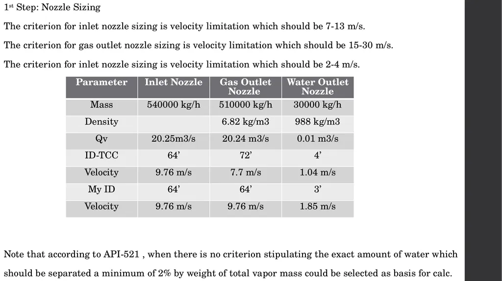
1st Step: Nozzle Sizing
The criterion for inlet nozzle sizing is velocity limitation which should be 7-13 m/s.
The criterion for gas outlet nozzle sizing is velocity limitation which should be 15-30 m/s.
The criterion for inlet nozzle sizing is velocity limitation which should be 2-4 m/s.
Note that according to API-521 , when there is no criterion stipulating the exact amount of water which
should be separated a minimum of 2% by weight of total vapor mass could be selected as basis for calc.<br>
The criterion for inlet nozzle sizing is velocity limitation which should be 7-13 m/s.
The criterion for gas outlet nozzle sizing is velocity limitation which should be 15-30 m/s.
The criterion for inlet nozzle sizing is velocity limitation which should be 2-4 m/s.
Note that according to API-521 , when there is no criterion stipulating the exact amount of water which
should be separated a minimum of 2% by weight of total vapor mass could be selected as basis for calc.<br>
24
But TCC has assumed 30000 m3/h as the rated capacity of K.O.D pump which is
Another matter is that the vendor has selected 72’ as outlet nozzle ID which is a bit bigger than what
the criterion stipulates. Perhaps the vendor was more concerned with droplet sizing so that the higher
the outlet nozzle ID, the lower particle sizing. Probably maximum 300 um has been taken for Design
Basis.<br>
Another matter is that the vendor has selected 72’ as outlet nozzle ID which is a bit bigger than what
the criterion stipulates. Perhaps the vendor was more concerned with droplet sizing so that the higher
the outlet nozzle ID, the lower particle sizing. Probably maximum 300 um has been taken for Design
Basis.<br>
25
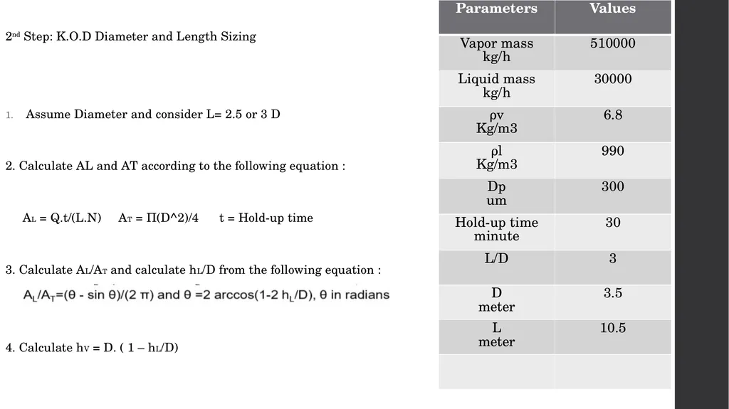
2nd Step: K.O.D Diameter and Length Sizing
Assume Diameter and consider L= 2.5 or 3 D
2. Calculate AL and AT according to the following equation :
AL = Q.t/(L.N) AT = П(D^2)/4 t = Hold-up time
3. Calculate AL/AT and calculate hL/D from the following equation :
4. Calculate hV = D. ( 1 – hL/D)<br>
Assume Diameter and consider L= 2.5 or 3 D
2. Calculate AL and AT according to the following equation :
AL = Q.t/(L.N) AT = П(D^2)/4 t = Hold-up time
3. Calculate AL/AT and calculate hL/D from the following equation :
4. Calculate hV = D. ( 1 – hL/D)<br>
26
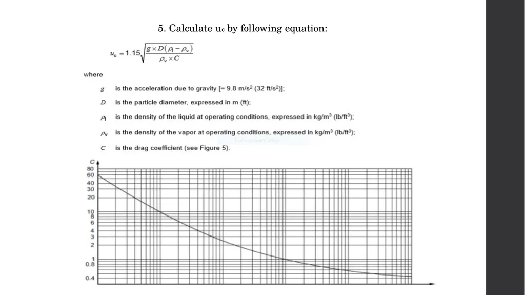
5. Calculate uc by following equation:<br>
27
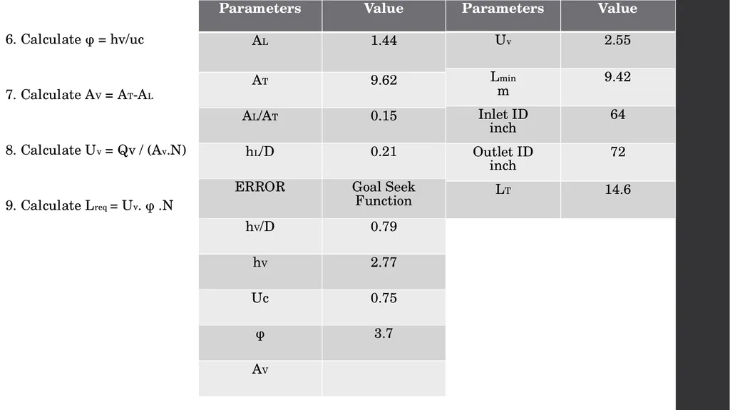
6. Calculate φ = hv/uc
7. Calculate AV = AT-AL
8. Calculate Uv = Qv / (Av.N)
9. Calculate Lreq = Uv. φ .N<br>
7. Calculate AV = AT-AL
8. Calculate Uv = Qv / (Av.N)
9. Calculate Lreq = Uv. φ .N<br>
28
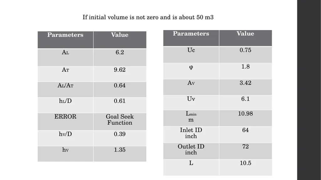
If initial volume is not zero and is about 50 m3<br>
29
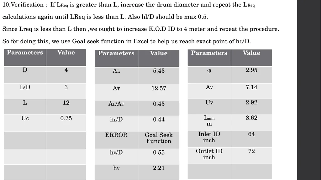
10.Verification : If LReq is greater than L, increase the drum diameter and repeat the LReq
calculations again until LReq is less than L. Also hl/D should be max 0.5.
Since Lreq is less than L then ,we ought to increase K.O.D ID to 4 meter and repeat the procedure.
So for doing this, we use Goal seek function in Excel to help us reach exact point of hL/D.<br>
calculations again until LReq is less than L. Also hl/D should be max 0.5.
Since Lreq is less than L then ,we ought to increase K.O.D ID to 4 meter and repeat the procedure.
So for doing this, we use Goal seek function in Excel to help us reach exact point of hL/D.<br>
30
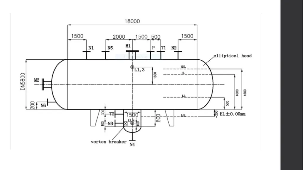
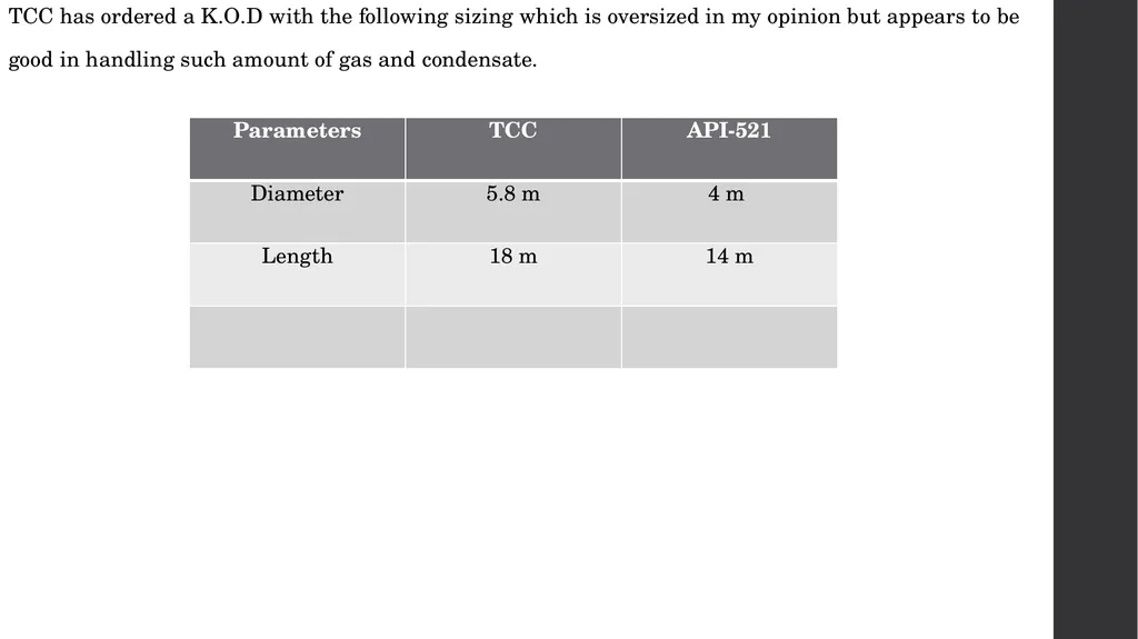
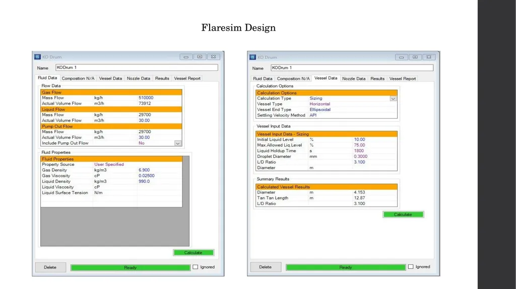
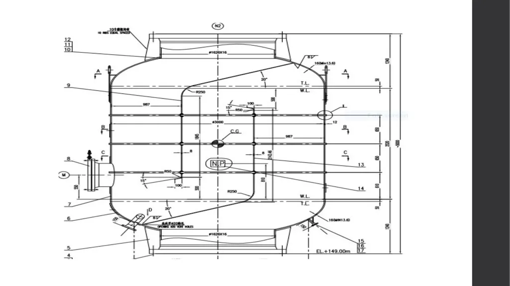
TCC has ordered a K.O.D with the following sizing which is oversized in my opinion but appears to be
good in handling such amount of gas and condensate.<br>
good in handling such amount of gas and condensate.<br>
31
Flaresim Design<br>
32
Flare Thermal Radiation Assessment
Based on
API-521 and Schlumberger Flaresim<br>
Based on
API-521 and Schlumberger Flaresim<br>
33
Calculation of Flare Stack Diameter
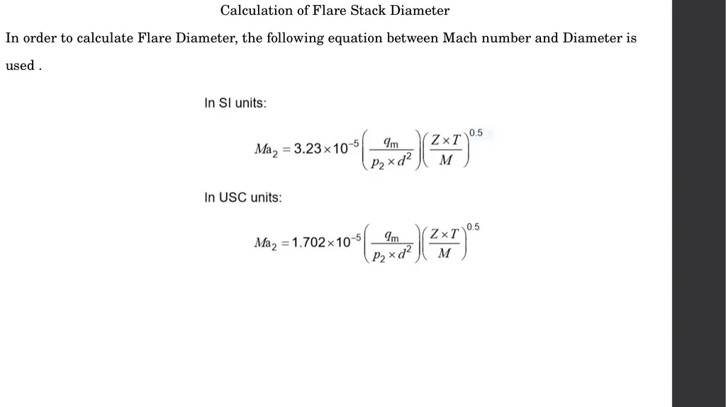
In order to calculate Flare Diameter, the following equation between Mach number and Diameter is
used .<br>
In order to calculate Flare Diameter, the following equation between Mach number and Diameter is
used .<br>
34
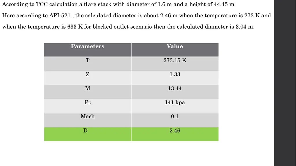
According to TCC calculation a flare stack with diameter of 1.6 m and a height of 44.45 m
Here according to API-521 , the calculated diameter is about 2.46 m when the temperature is 273 K and
when the temperature is 633 K for blocked outlet scenario then the calculated diameter is 3.04 m.<br>
Here according to API-521 , the calculated diameter is about 2.46 m when the temperature is 273 K and
when the temperature is 633 K for blocked outlet scenario then the calculated diameter is 3.04 m.<br>
35
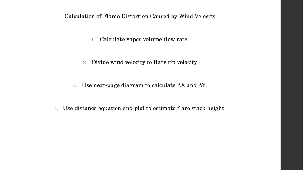
Calculation of Flame Distortion Caused by Wind Velocity
Calculate vapor volume flow rate
Divide wind velocity to flare tip velocity
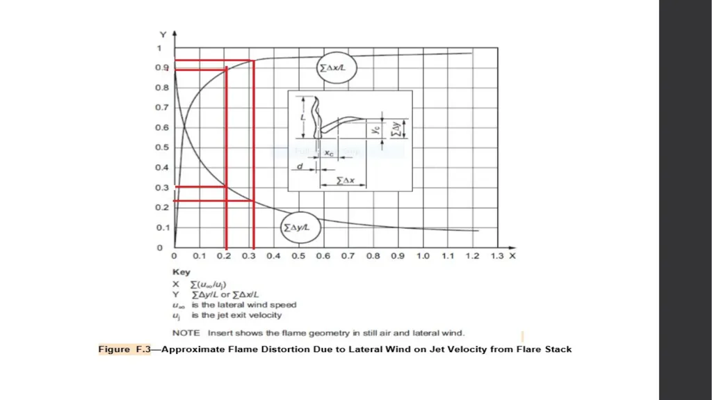
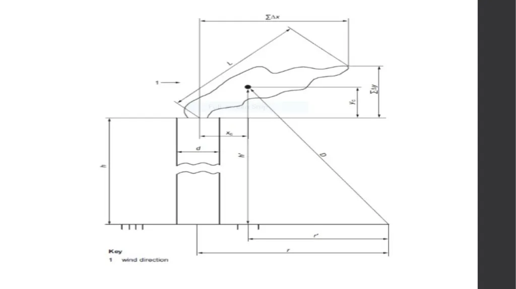
Use next-page diagram to calculate ∆X and ∆Y.
Use distance equation and plot to estimate flare stack height.<br>
Calculate vapor volume flow rate
Divide wind velocity to flare tip velocity
Use next-page diagram to calculate ∆X and ∆Y.
Use distance equation and plot to estimate flare stack height.<br>
36
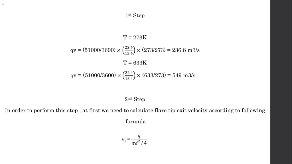
T=273K
uj = 49.6 m/s
T=633K
uj = 75 m/s
So now wind velocity to tip velocity is divided by taking into account 16 m/s as local wind velocity
T=273K
u/uj = 0.32
T=633K
u/uj = 0.21
T=633K
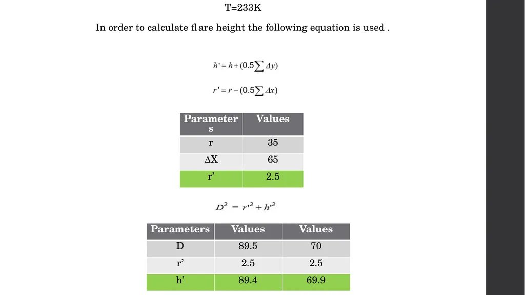
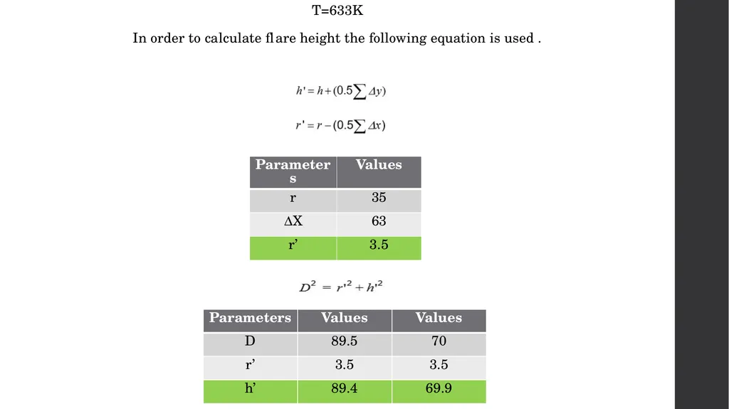
According to next-page diagram, ∆Y/L = 0.3 therefore ∆Y = 21m
According to next-page diagram, ∆X/L = 0.9 therefore ∆X = 63m
T=273K
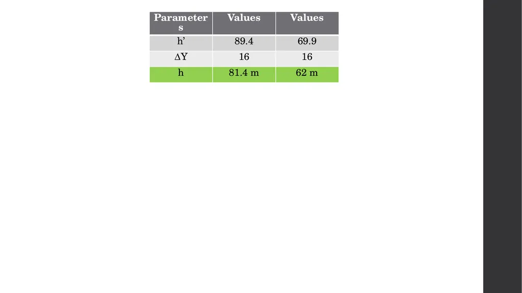
According to next-page diagram, ∆Y/L = 0.23 therefore ∆Y = 16m
According to next-page diagram, ∆X/L = 0.93 therefore ∆X = 65m<br>
uj = 49.6 m/s
T=633K
uj = 75 m/s
So now wind velocity to tip velocity is divided by taking into account 16 m/s as local wind velocity
T=273K
u/uj = 0.32
T=633K
u/uj = 0.21
T=633K
According to next-page diagram, ∆Y/L = 0.3 therefore ∆Y = 21m
According to next-page diagram, ∆X/L = 0.9 therefore ∆X = 63m
T=273K
According to next-page diagram, ∆Y/L = 0.23 therefore ∆Y = 16m
According to next-page diagram, ∆X/L = 0.93 therefore ∆X = 65m<br>
37
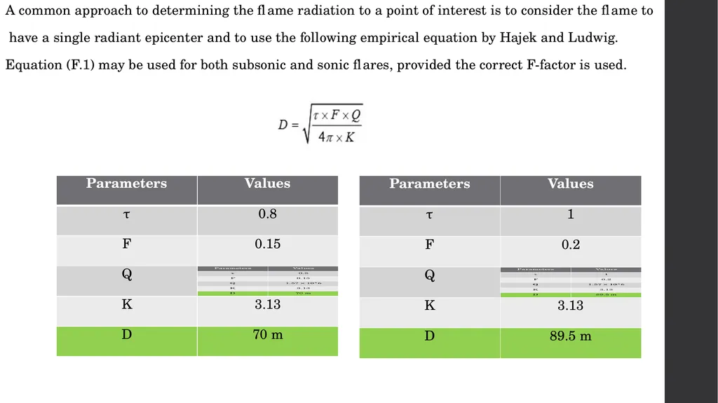
A common approach to determining the flame radiation to a point of interest is to consider the flame to
have a single radiant epicenter and to use the following empirical equation by Hajek and Ludwig.
Equation (F.1) may be used for both subsonic and sonic flares, provided the correct F-factor is used.<br>
have a single radiant epicenter and to use the following empirical equation by Hajek and Ludwig.
Equation (F.1) may be used for both subsonic and sonic flares, provided the correct F-factor is used.<br>
38
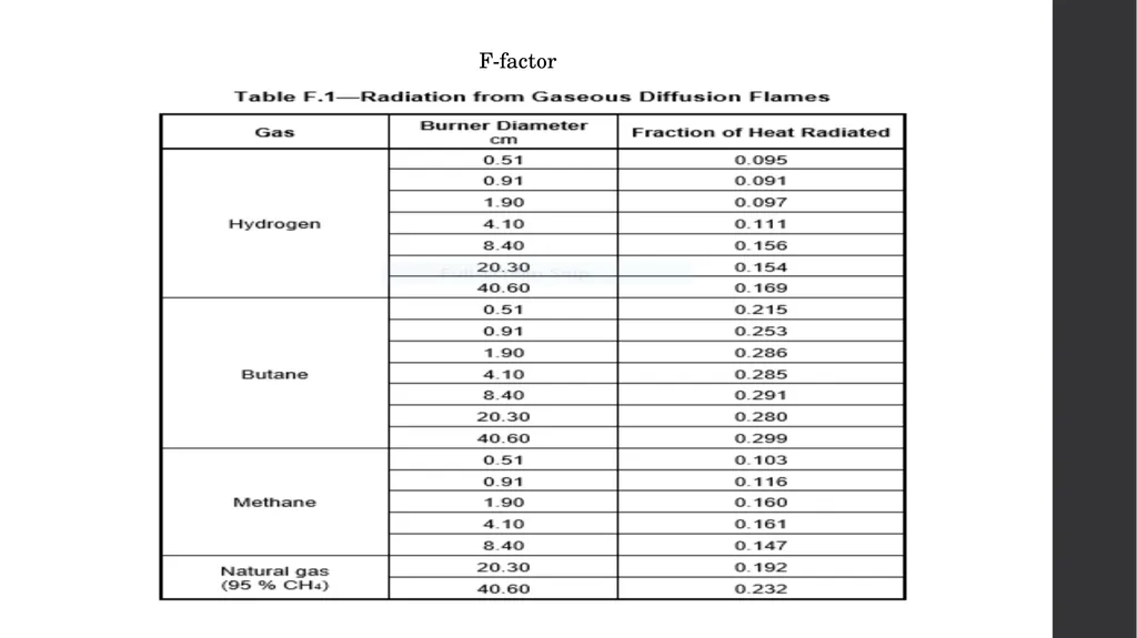
F-factor<br>
39
T=233K
In order to calculate flare height the following equation is used .<br>
In order to calculate flare height the following equation is used .<br>
40
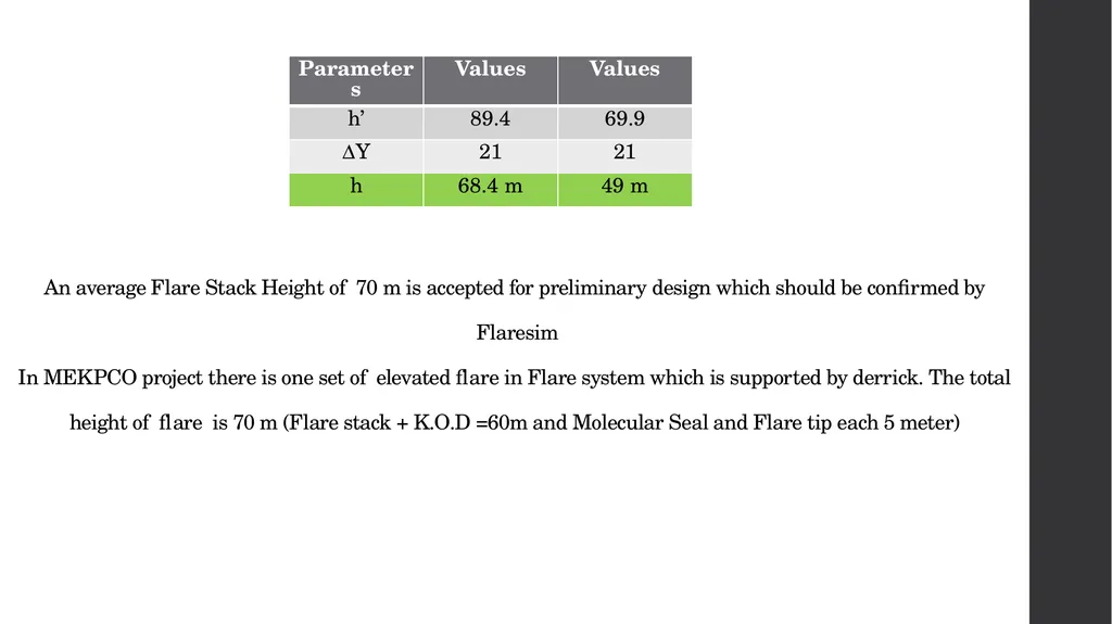
T=633K
In order to calculate flare height the following equation is used .<br>
In order to calculate flare height the following equation is used .<br>
41
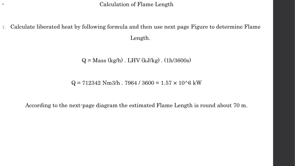
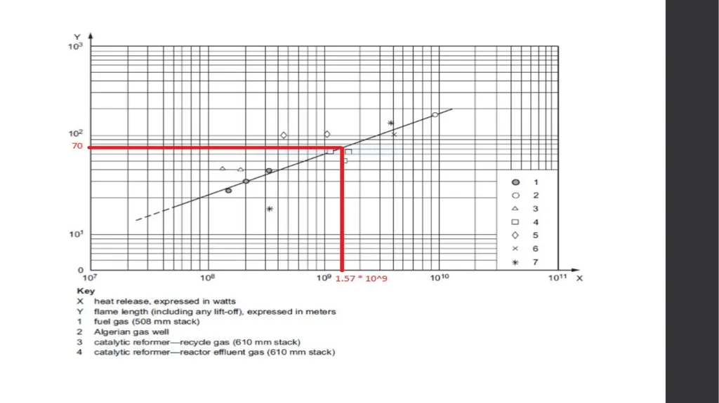
An average Flare Stack Height of 70 m is accepted for preliminary design which should be confirmed by
Flaresim
In MEKPCO project there is one set of elevated flare in Flare system which is supported by derrick. The total
height of flare is 70 m (Flare stack + K.O.D =60m and Molecular Seal and Flare tip each 5 meter)<br>
42
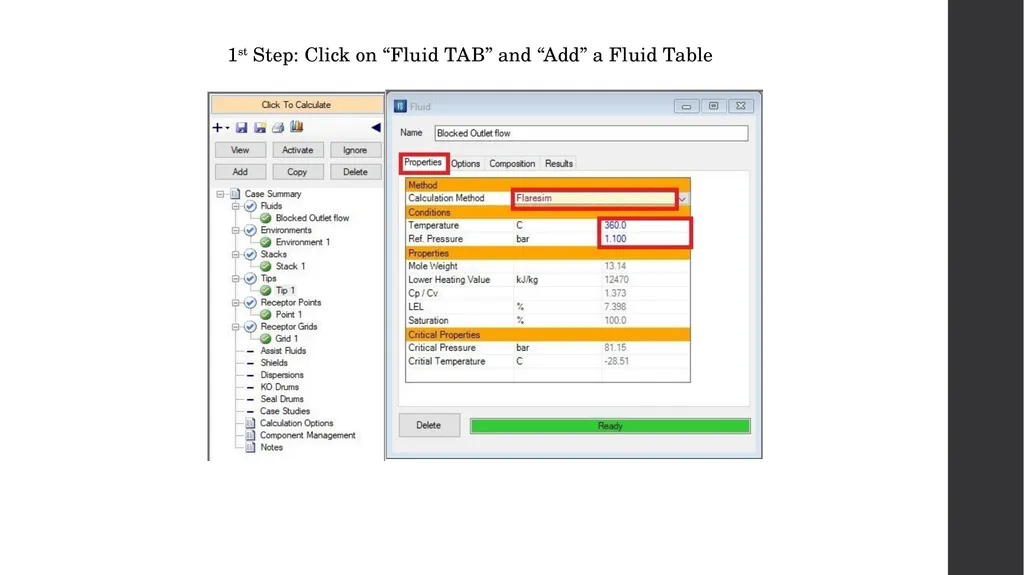
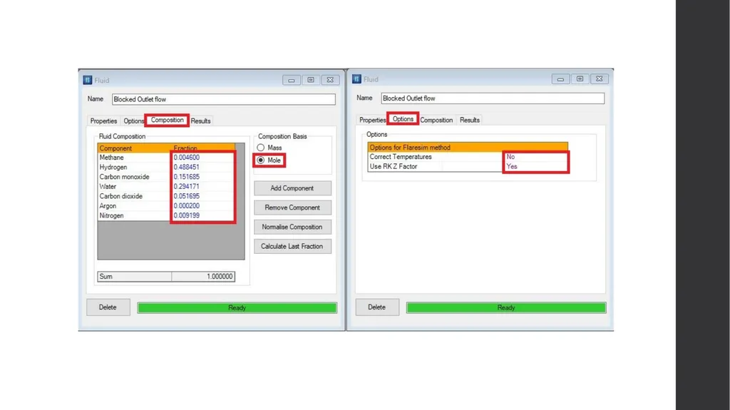
1st Step: Click on “Fluid TAB” and “Add” a Fluid Table<br>
43
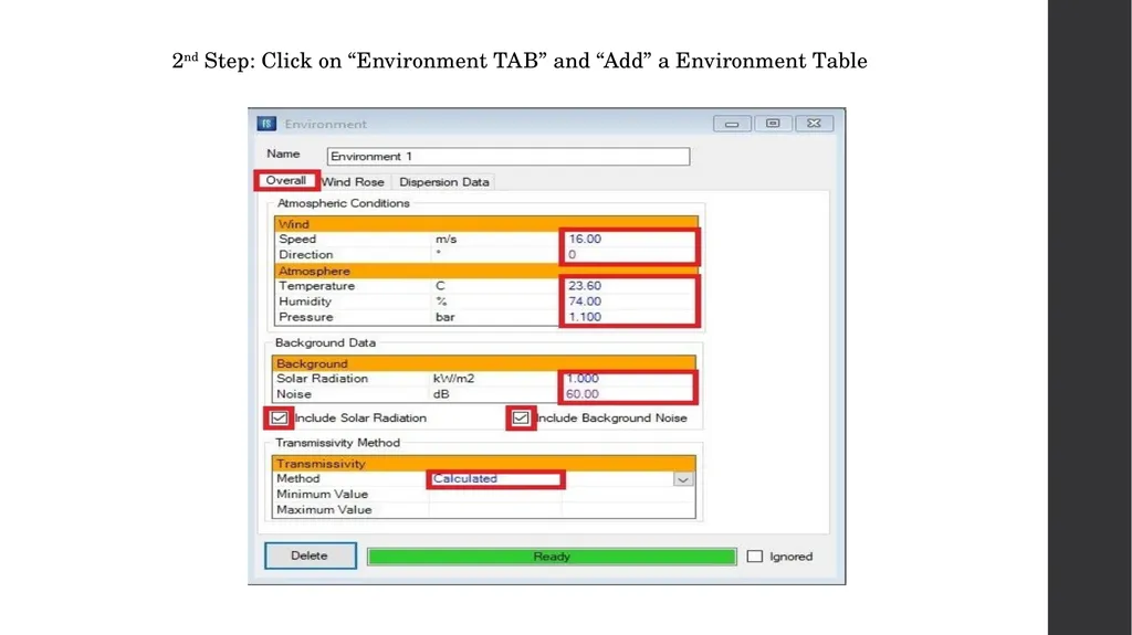
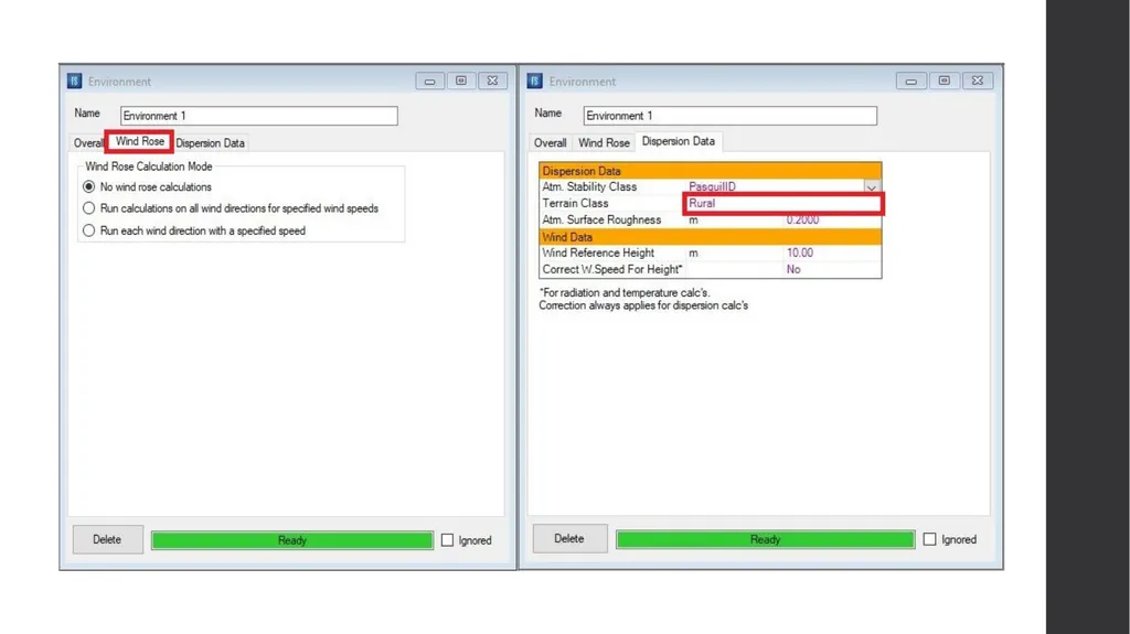
2nd Step: Click on “Environment TAB” and “Add” a Environment Table<br>
44
Thermal Radiation and Noise Criteria
According to API-521, the followings are important to notice when designing a flare stack.
Recommended Design Thermal Radiation for Personnel<br>
According to API-521, the followings are important to notice when designing a flare stack.
Recommended Design Thermal Radiation for Personnel<br>
45
The incident solar radiation for the site. Typical values for different geographical locations are given in
the following table.
The decision on whether to include solar radiation when designing flare systems is one for the user.
API 521 recommends that this be considered on a case by case basis. Some consider it more realistic to
exclude solar radiation in calculations.
In deciding whether to include solar radiation consideration should be given to the frequency and
duration of the flaring event, the probability of personnel being present in the exposed location, the
possibility of sun and flare radiation impinging from the same general direction, the likelihood of
protective clothing being worn and the ease or difficulty of escape from the exposed location.<br>
the following table.
The decision on whether to include solar radiation when designing flare systems is one for the user.
API 521 recommends that this be considered on a case by case basis. Some consider it more realistic to
exclude solar radiation in calculations.
In deciding whether to include solar radiation consideration should be given to the frequency and
duration of the flaring event, the probability of personnel being present in the exposed location, the
possibility of sun and flare radiation impinging from the same general direction, the likelihood of
protective clothing being worn and the ease or difficulty of escape from the exposed location.<br>
46
Including solar radiation leads to more conservative designs and its impact can be significant if the
flare system design is controlled by low total radiation limits at longer distances from the flare.
Determining whether solar radiation has been included or excluded is important when comparing flare
system designs.
In MEKPCO Project , solar radiation has been included.<br>
flare system design is controlled by low total radiation limits at longer distances from the flare.
Determining whether solar radiation has been included or excluded is important when comparing flare
system designs.
In MEKPCO Project , solar radiation has been included.<br>
47
Noise
The background noise is used as a reference noise level to which the noise from the flare system is
added.
In MEKPCO Project, a typical value of 60 dB has been selected for background noise.<br>
The background noise is used as a reference noise level to which the noise from the flare system is
added.
In MEKPCO Project, a typical value of 60 dB has been selected for background noise.<br>
48
Stability Class
PasquillA through PasquillF
This defines the atmospheric stability class to be used to characterize the atmospheric turbulence for
both Gaussian and jet dispersion calculations.
Flaresim uses the widely used Pasquil stability class designation from A to F where A is the most
turbulent or most unstable atmosphere and F the least turbulent or most stable.
Here as typical, PasquillD is selected.
10 meter high is reference height at which the wind speed is specified. This will be used together with
the atmosphere and terrain characterization information to calculate the wind speed at a given height
when required.<br>
PasquillA through PasquillF
This defines the atmospheric stability class to be used to characterize the atmospheric turbulence for
both Gaussian and jet dispersion calculations.
Flaresim uses the widely used Pasquil stability class designation from A to F where A is the most
turbulent or most unstable atmosphere and F the least turbulent or most stable.
Here as typical, PasquillD is selected.
10 meter high is reference height at which the wind speed is specified. This will be used together with
the atmosphere and terrain characterization information to calculate the wind speed at a given height
when required.<br>
49
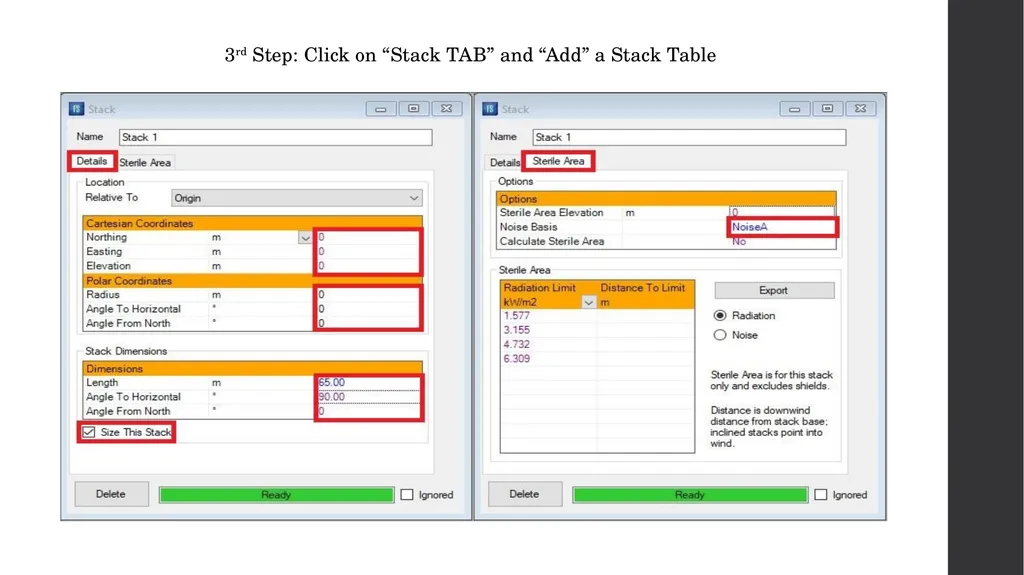
3rd Step: Click on “Stack TAB” and “Add” a Stack Table<br>
50
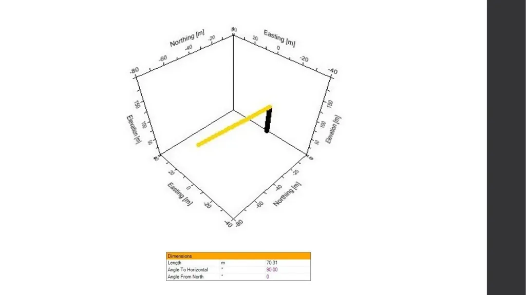
At first estimation, a stack length of 65 m is selected. Since the stack is vertical a 90 degrees for
Horizontal angle is selected.
Notice that Noise A means Noise weighted for human ear sensitivity<br>
Horizontal angle is selected.
Notice that Noise A means Noise weighted for human ear sensitivity<br>
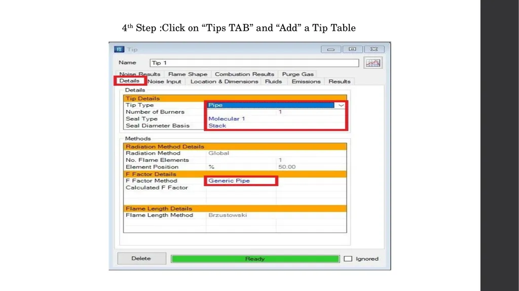
51
4th Step :Click on “Tips TAB” and “Add” a Tip Table<br>
52
For gases, either the pipe or sonic tip types may be selected. Pipe flares are the simplest type of tip
and may be specified for both high and low pressure gases. If the pressure available is greater than 2
bar (30 psi) at the tip then a sonic tip can be utilised. Sonic flare tips have the advantage of low flame
emissivities due to more efficient combustion of the flare gas. For lower pressures a pipe flare is
generally used possibly with steam or air Assist fluid.
Where a combined HP/LP tips is selected the HP tip is assumed to be a sonic tip and the LP a sub-
sonic one. The flow ratio of HP to LP fluids should be 3 or greater.
For liquids a Welltest tip type should be selected.
In MEKPCO Project, Pipe is selected.<br>
and may be specified for both high and low pressure gases. If the pressure available is greater than 2
bar (30 psi) at the tip then a sonic tip can be utilised. Sonic flare tips have the advantage of low flame
emissivities due to more efficient combustion of the flare gas. For lower pressures a pipe flare is
generally used possibly with steam or air Assist fluid.
Where a combined HP/LP tips is selected the HP tip is assumed to be a sonic tip and the LP a sub-
sonic one. The flow ratio of HP to LP fluids should be 3 or greater.
For liquids a Welltest tip type should be selected.
In MEKPCO Project, Pipe is selected.<br>
53
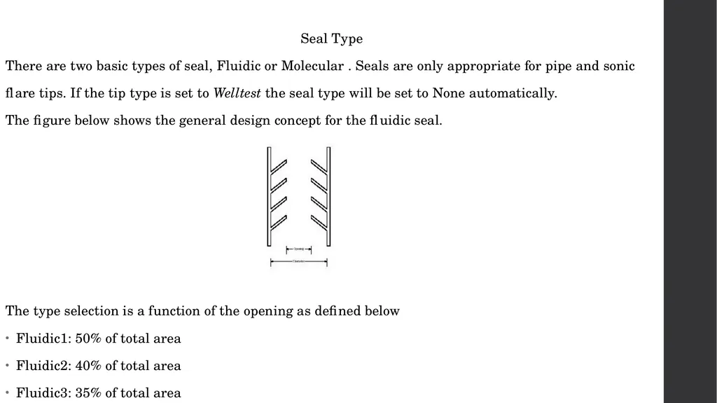
Seal Type
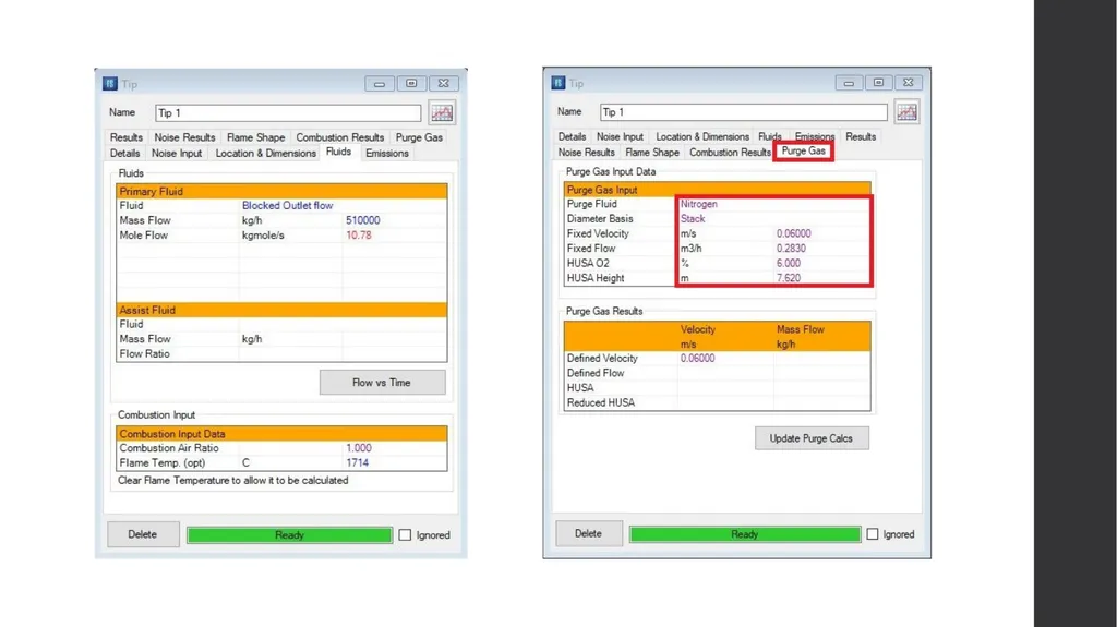
There are two basic types of seal, Fluidic or Molecular . Seals are only appropriate for pipe and sonic
flare tips. If the tip type is set to Welltest the seal type will be set to None automatically.
The figure below shows the general design concept for the fluidic seal.
The type selection is a function of the opening as defined below
Fluidic1: 50% of total area
Fluidic2: 40% of total area
Fluidic3: 35% of total area<br>
There are two basic types of seal, Fluidic or Molecular . Seals are only appropriate for pipe and sonic
flare tips. If the tip type is set to Welltest the seal type will be set to None automatically.
The figure below shows the general design concept for the fluidic seal.
The type selection is a function of the opening as defined below
Fluidic1: 50% of total area
Fluidic2: 40% of total area
Fluidic3: 35% of total area<br>
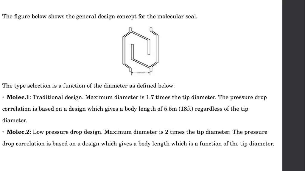
54
The figure below shows the general design concept for the molecular seal.
The type selection is a function of the diameter as defined below:
Molec.1: Traditional design. Maximum diameter is 1.7 times the tip diameter. The pressure drop
correlation is based on a design which gives a body length of 5.5m (18ft) regardless of the tip
diameter.
Molec.2: Low pressure drop design. Maximum diameter is 2 times the tip diameter. The pressure
drop correlation is based on a design which gives a body length which is a function of the tip diameter.<br>
The type selection is a function of the diameter as defined below:
Molec.1: Traditional design. Maximum diameter is 1.7 times the tip diameter. The pressure drop
correlation is based on a design which gives a body length of 5.5m (18ft) regardless of the tip
diameter.
Molec.2: Low pressure drop design. Maximum diameter is 2 times the tip diameter. The pressure
drop correlation is based on a design which gives a body length which is a function of the tip diameter.<br>
55
The fluidic seal has a number of advantages over the traditional molecular seal:-
Lower purge gas requirements and consequent operating costs.
The seal still operates with a high efficiency even if rain water or chunks of refractory material drop
into the baffles. In fact the water is quickly dissipated because the fluidic seal is located at a high
temperature section of the flare stack.
Lower cost due to the simple construction and light weight. A 48" fluidic seal will typically weigh less
than half the weight of a 6" molecular seal.
In MEKPCO Project, Molecular 1 is selected.<br>
Lower purge gas requirements and consequent operating costs.
The seal still operates with a high efficiency even if rain water or chunks of refractory material drop
into the baffles. In fact the water is quickly dissipated because the fluidic seal is located at a high
temperature section of the flare stack.
Lower cost due to the simple construction and light weight. A 48" fluidic seal will typically weigh less
than half the weight of a 6" molecular seal.
In MEKPCO Project, Molecular 1 is selected.<br>
56
Seal Diameter Basis
This entry defines whether the seal calculations are based on the tip diameter or stack diameter.
effectively this specifies whether the seal is located within the tip or the stack.
Here Stack has been selected.<br>
This entry defines whether the seal calculations are based on the tip diameter or stack diameter.
effectively this specifies whether the seal is located within the tip or the stack.
Here Stack has been selected.<br>
57
F Factor
The fraction of the total net heat release from the flame which is radiated.
Natural gas: Correlation based on tip exit velocity assuming a natural gas fluid of molecular weight
19.
Tan: Correlation based on mole weight
Kent: Correlation based on mole weight
High Efficiency: Proprietary correlation between tip type, exit velocity, fluid molecular weight and
degree of hydrocarbon saturation. Formally known as the Flaresim method in versions prior to 1.2.
Cook: Correlation based on exit velocity.
Generic Pipe: Correlation based on refitting Kent, Tan, Natural gas and Cook methods across a range
of exit velocities and molecular weights.
Modified. Chamberlain: Correlation based on mole weight and exit velocity.<br>
The fraction of the total net heat release from the flame which is radiated.
Natural gas: Correlation based on tip exit velocity assuming a natural gas fluid of molecular weight
19.
Tan: Correlation based on mole weight
Kent: Correlation based on mole weight
High Efficiency: Proprietary correlation between tip type, exit velocity, fluid molecular weight and
degree of hydrocarbon saturation. Formally known as the Flaresim method in versions prior to 1.2.
Cook: Correlation based on exit velocity.
Generic Pipe: Correlation based on refitting Kent, Tan, Natural gas and Cook methods across a range
of exit velocities and molecular weights.
Modified. Chamberlain: Correlation based on mole weight and exit velocity.<br>
58
Which one to select?
Where flare vendor data is available it should be used in preference to a correlation. In the absence of
vendor data, the Generic Pipe method is recommended for a conservative design. For clean burning,
smokeless flares from well designed flare tips in good condition the High Efficiency method can be used.
In practice this means flares burning paraffinic hydrocarbons of low molecular weight fluid (<60) at
reasonable exit velocities (> 0.2 mach). For fluids other than paraffinic hydrocarbons vendor advice
should be sought. In the absence of advice, user specified F Factors of 0.3 to 0.4 are generally
reasonable.
If the Fraction Heat Radiated Method is set to User Specified then the required value for the fraction of
heat radiated must be entered here. Otherwise the calculated result for the selected calculation method
will be displayed after the model has been run.
Here Generic Pipe is selected.<br>
Where flare vendor data is available it should be used in preference to a correlation. In the absence of
vendor data, the Generic Pipe method is recommended for a conservative design. For clean burning,
smokeless flares from well designed flare tips in good condition the High Efficiency method can be used.
In practice this means flares burning paraffinic hydrocarbons of low molecular weight fluid (<60) at
reasonable exit velocities (> 0.2 mach). For fluids other than paraffinic hydrocarbons vendor advice
should be sought. In the absence of advice, user specified F Factors of 0.3 to 0.4 are generally
reasonable.
If the Fraction Heat Radiated Method is set to User Specified then the required value for the fraction of
heat radiated must be entered here. Otherwise the calculated result for the selected calculation method
will be displayed after the model has been run.
Here Generic Pipe is selected.<br>
59
Flame Length Method
API - Flame length is calculated from heat released according to equation presented in API 521.
FLARESIM - Flame length is calculated from heat released using following equation.
Where
L is flame length in m Q is heat release in J/s N is number of tips The constants I1 and I2 take the following values for different tip types
Brzustowski - Flame length is calculated from flammability limits using Brzustowski & Sommer method
Here Brzustowski is selected by the Flaresim.<br>
API - Flame length is calculated from heat released according to equation presented in API 521.
FLARESIM - Flame length is calculated from heat released using following equation.
Where
L is flame length in m Q is heat release in J/s N is number of tips The constants I1 and I2 take the following values for different tip types
Brzustowski - Flame length is calculated from flammability limits using Brzustowski & Sommer method
Here Brzustowski is selected by the Flaresim.<br>
60
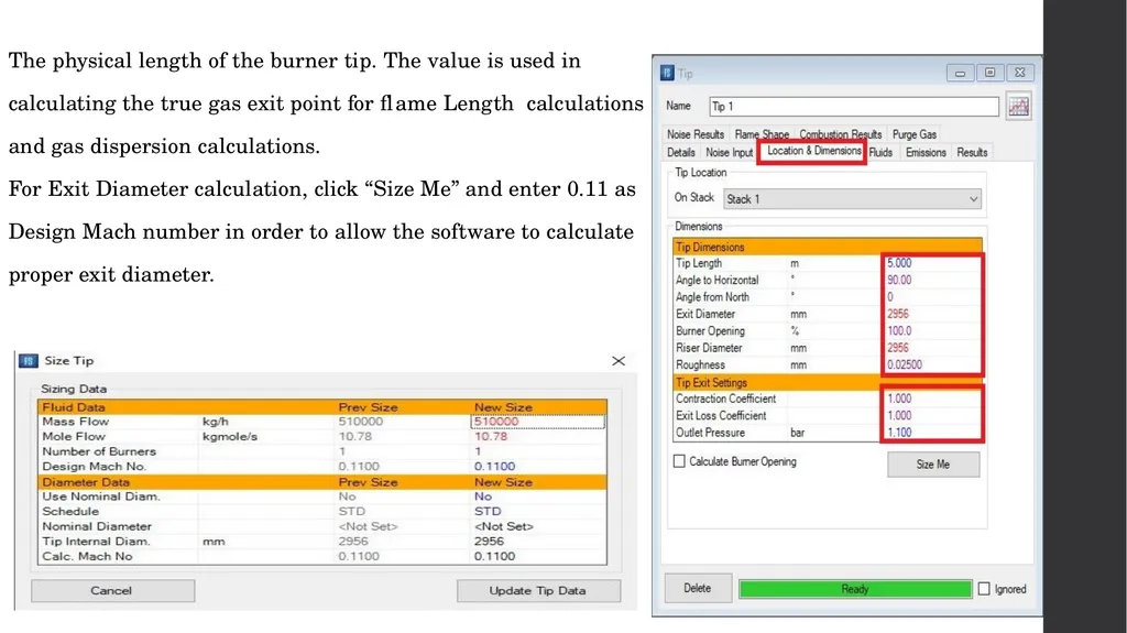
The physical length of the burner tip. The value is used in
calculating the true gas exit point for flame Length calculations
and gas dispersion calculations.
For Exit Diameter calculation, click “Size Me” and enter 0.11 as
Design Mach number in order to allow the software to calculate
proper exit diameter.<br>
calculating the true gas exit point for flame Length calculations
and gas dispersion calculations.
For Exit Diameter calculation, click “Size Me” and enter 0.11 as
Design Mach number in order to allow the software to calculate
proper exit diameter.<br>
61
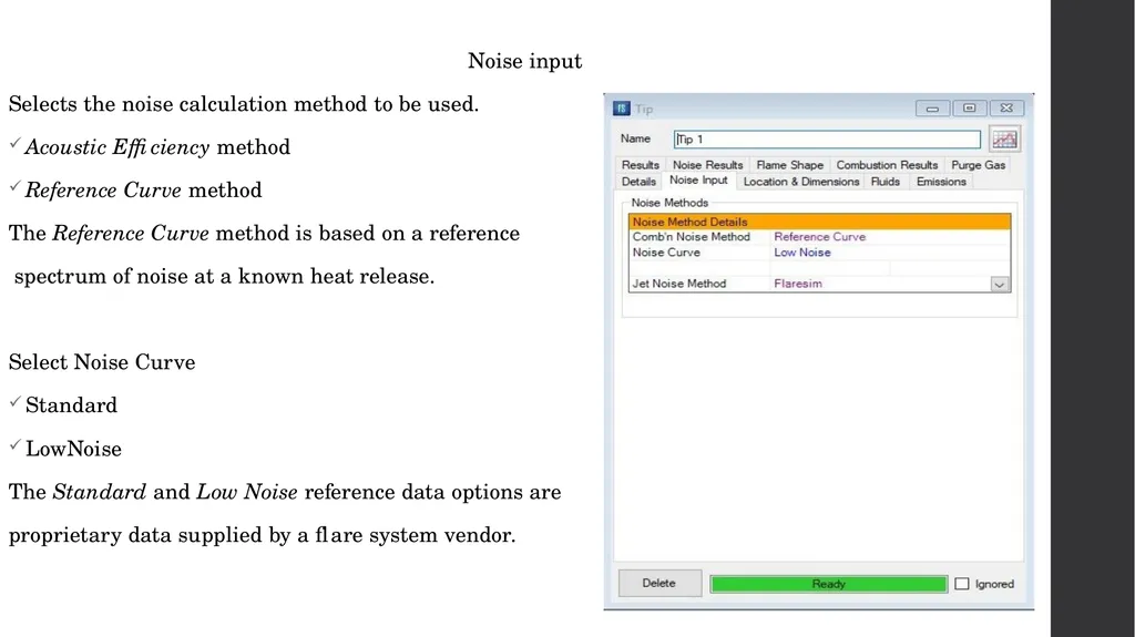
Noise input
Selects the noise calculation method to be used.
Acoustic Efficiency method
Reference Curve method
The Reference Curve method is based on a reference
spectrum of noise at a known heat release.
Select Noise Curve
Standard
LowNoise
The Standard and Low Noise reference data options are
proprietary data supplied by a flare system vendor.<br>
Selects the noise calculation method to be used.
Acoustic Efficiency method
Reference Curve method
The Reference Curve method is based on a reference
spectrum of noise at a known heat release.
Select Noise Curve
Standard
LowNoise
The Standard and Low Noise reference data options are
proprietary data supplied by a flare system vendor.<br>
62
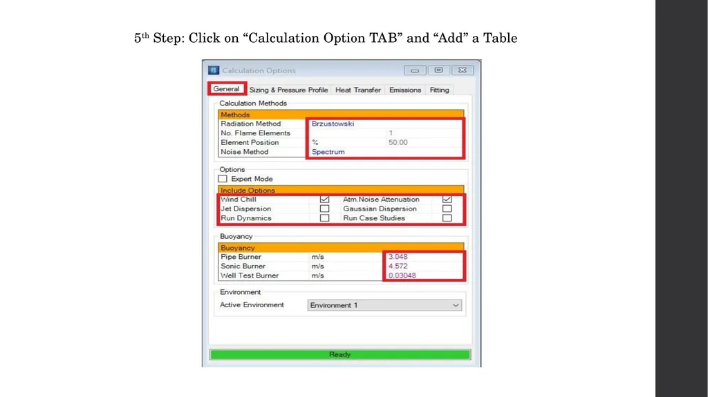
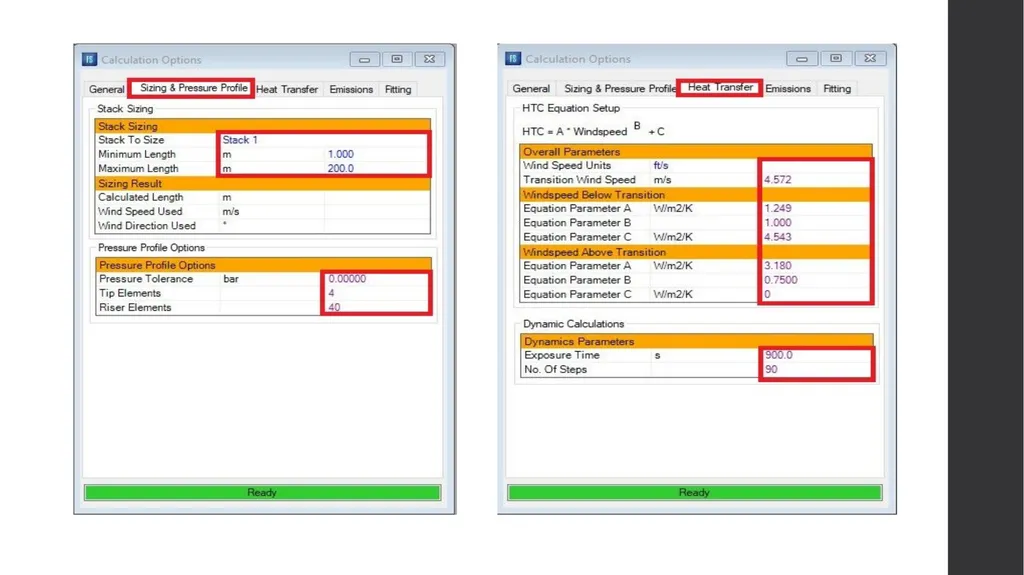
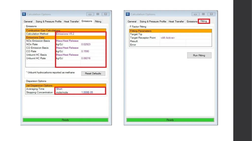
5th Step: Click on “Calculation Option TAB” and “Add” a Table<br>
63
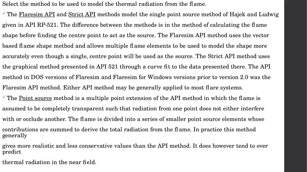
Select the method to be used to model the thermal radiation from the flame.
The Flaresim API and Strict API methods model the single point source method of Hajek and Ludwig
given in API RP-521. The difference between the methods is in the method of calculating the flame
shape before finding the centre point to act as the source. The Flaresim API method uses the vector
based flame shape method and allows multiple flame elements to be used to model the shape more
accurately even though a single, centre point will be used as the source. The Strict API method uses
the graphical method presented in API 521 through a curve fit to the data presented there. The API
method in DOS versions of Flaresim and Flaresim for Windows versions prior to version 2.0 was the
Flaresim API method. Either API method may be generally applied to most flare systems.
The Point source method is a multiple point extension of the API method in which the flame is
assumed to be completely transparent such that radiation from one point does not either interfere
with or occlude another. The flame is divided into a series of smaller point source elements whose
contributions are summed to derive the total radiation from the flame. In practice this method generally
gives more realistic and less conservative values than the API method. It does however tend to over predict
thermal radiation in the near field.<br>
The Flaresim API and Strict API methods model the single point source method of Hajek and Ludwig
given in API RP-521. The difference between the methods is in the method of calculating the flame
shape before finding the centre point to act as the source. The Flaresim API method uses the vector
based flame shape method and allows multiple flame elements to be used to model the shape more
accurately even though a single, centre point will be used as the source. The Strict API method uses
the graphical method presented in API 521 through a curve fit to the data presented there. The API
method in DOS versions of Flaresim and Flaresim for Windows versions prior to version 2.0 was the
Flaresim API method. Either API method may be generally applied to most flare systems.
The Point source method is a multiple point extension of the API method in which the flame is
assumed to be completely transparent such that radiation from one point does not either interfere
with or occlude another. The flame is divided into a series of smaller point source elements whose
contributions are summed to derive the total radiation from the flame. In practice this method generally
gives more realistic and less conservative values than the API method. It does however tend to over predict
thermal radiation in the near field.<br>
64
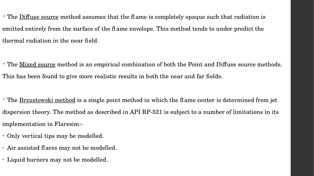
The Diffuse source method assumes that the flame is completely opaque such that radiation is
emitted entirely from the surface of the flame envelope. This method tends to under predict the
thermal radiation in the near field.
The Mixed source method is an empirical combination of both the Point and Diffuse source methods.
This has been found to give more realistic results in both the near and far fields.
The Brzustowski method is a single point method in which the flame center is determined from jet
dispersion theory. The method as described in API RP-521 is subject to a number of limitations in its
implementation in Flaresim:-
Only vertical tips may be modelled.
Air assisted flares may not be modelled.
Liquid burners may not be modelled.<br>
emitted entirely from the surface of the flame envelope. This method tends to under predict the
thermal radiation in the near field.
The Mixed source method is an empirical combination of both the Point and Diffuse source methods.
This has been found to give more realistic results in both the near and far fields.
The Brzustowski method is a single point method in which the flame center is determined from jet
dispersion theory. The method as described in API RP-521 is subject to a number of limitations in its
implementation in Flaresim:-
Only vertical tips may be modelled.
Air assisted flares may not be modelled.
Liquid burners may not be modelled.<br>
65
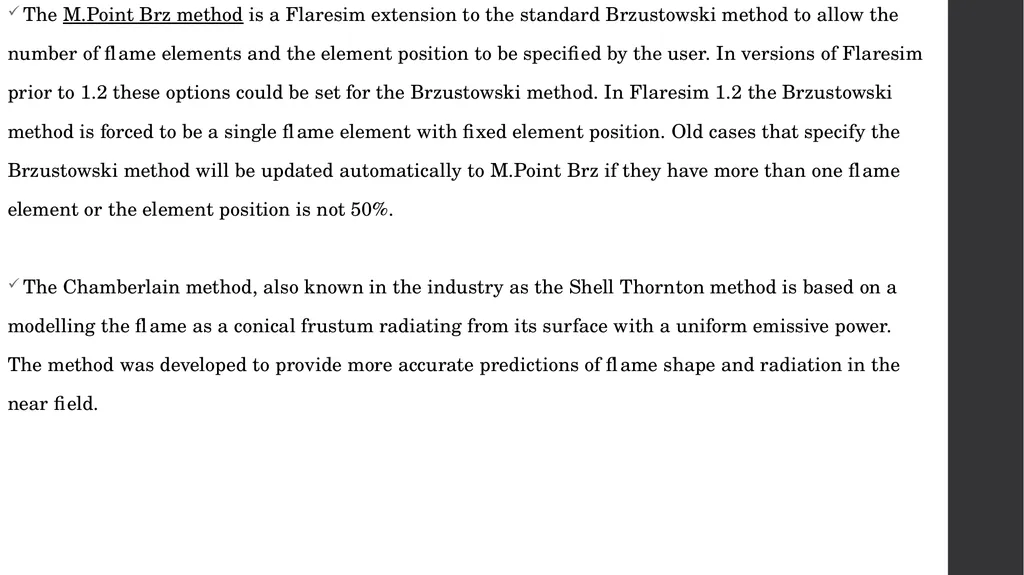
The M.Point Brz method is a Flaresim extension to the standard Brzustowski method to allow the
number of flame elements and the element position to be specified by the user. In versions of Flaresim
prior to 1.2 these options could be set for the Brzustowski method. In Flaresim 1.2 the Brzustowski
method is forced to be a single flame element with fixed element position. Old cases that specify the
Brzustowski method will be updated automatically to M.Point Brz if they have more than one flame
element or the element position is not 50%.
The Chamberlain method, also known in the industry as the Shell Thornton method is based on a
modelling the flame as a conical frustum radiating from its surface with a uniform emissive power.
The method was developed to provide more accurate predictions of flame shape and radiation in the
near field.<br>
number of flame elements and the element position to be specified by the user. In versions of Flaresim
prior to 1.2 these options could be set for the Brzustowski method. In Flaresim 1.2 the Brzustowski
method is forced to be a single flame element with fixed element position. Old cases that specify the
Brzustowski method will be updated automatically to M.Point Brz if they have more than one flame
element or the element position is not 50%.
The Chamberlain method, also known in the industry as the Shell Thornton method is based on a
modelling the flame as a conical frustum radiating from its surface with a uniform emissive power.
The method was developed to provide more accurate predictions of flame shape and radiation in the
near field.<br>
66
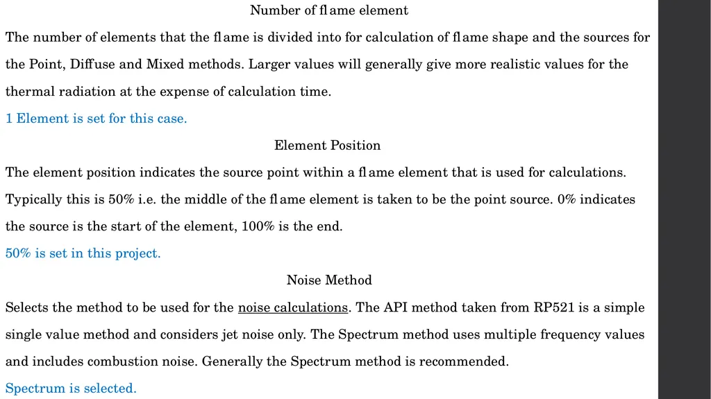
Number of flame element
The number of elements that the flame is divided into for calculation of flame shape and the sources for
the Point, Diffuse and Mixed methods. Larger values will generally give more realistic values for the
thermal radiation at the expense of calculation time.
1 Element is set for this case.
Element Position
The element position indicates the source point within a flame element that is used for calculations.
Typically this is 50% i.e. the middle of the flame element is taken to be the point source. 0% indicates
the source is the start of the element, 100% is the end.
50% is set in this project.
Noise Method
Selects the method to be used for the noise calculations. The API method taken from RP521 is a simple
single value method and considers jet noise only. The Spectrum method uses multiple frequency values
and includes combustion noise. Generally the Spectrum method is recommended.
Spectrum is selected.<br>
The number of elements that the flame is divided into for calculation of flame shape and the sources for
the Point, Diffuse and Mixed methods. Larger values will generally give more realistic values for the
thermal radiation at the expense of calculation time.
1 Element is set for this case.
Element Position
The element position indicates the source point within a flame element that is used for calculations.
Typically this is 50% i.e. the middle of the flame element is taken to be the point source. 0% indicates
the source is the start of the element, 100% is the end.
50% is set in this project.
Noise Method
Selects the method to be used for the noise calculations. The API method taken from RP521 is a simple
single value method and considers jet noise only. The Spectrum method uses multiple frequency values
and includes combustion noise. Generally the Spectrum method is recommended.
Spectrum is selected.<br>
67
Windchill
When set an empirical Windchill correlation is used to correct the incident thermal radiation at any
receptor point by taking into account the heat losses due to passage of wind over the point. Use of this
option will generally be a matter of individual judgement or your company standards.
It is recommended that you do not use this option if you are interested in the surface temperature
calculations. Note that effective of wind on convective heat transfer in the surface temperature
calculations is independent of the setting of this option.
Atm. Noise Attenuation
When set a correction will be applied to the noise calculations to allow for the attenuation in noise due to
atmospheric absorption. This option should normally be set<br>
When set an empirical Windchill correlation is used to correct the incident thermal radiation at any
receptor point by taking into account the heat losses due to passage of wind over the point. Use of this
option will generally be a matter of individual judgement or your company standards.
It is recommended that you do not use this option if you are interested in the surface temperature
calculations. Note that effective of wind on convective heat transfer in the surface temperature
calculations is independent of the setting of this option.
Atm. Noise Attenuation
When set a correction will be applied to the noise calculations to allow for the attenuation in noise due to
atmospheric absorption. This option should normally be set<br>
68
Jet Dispersion
Selecting this enables the jet dispersion calculations and will calculate concentrations of flare fluid at
receptor points and for receptor grids under flame out conditions
Gaussian Dispersion
Selecting this enables the calculations for all Gaussian Dispersion objects defined in the model
Run Dynamics
Selecting this enables dynamics calculations to be run to evaluate the change in radiation and other
results with time as the flare flow varies with time. The variation in flare flow with time must be
defined on the Tip Dynamics View and the results variation with time can be viewed on the Receptor
Point Dynamics View
The dynamics calculations are run in addition to the defined base case. Receptor Grid objects and
Dispersion objects are not included int the dynamic calculations<br>
Selecting this enables the jet dispersion calculations and will calculate concentrations of flare fluid at
receptor points and for receptor grids under flame out conditions
Gaussian Dispersion
Selecting this enables the calculations for all Gaussian Dispersion objects defined in the model
Run Dynamics
Selecting this enables dynamics calculations to be run to evaluate the change in radiation and other
results with time as the flare flow varies with time. The variation in flare flow with time must be
defined on the Tip Dynamics View and the results variation with time can be viewed on the Receptor
Point Dynamics View
The dynamics calculations are run in addition to the defined base case. Receptor Grid objects and
Dispersion objects are not included int the dynamic calculations<br>
69
Buoyancy
For all methods except the Brzustowski and Chamberlain methods, the flame shape is calculated by
resolving the velocity vectors in three dimensions. The main components are the tip exit velocity and
the wind velocity. There is however an additional velocity component which is due to the density
differences between the hot combustion gases and the surrounding air. This is referred to as the flame
buoyancy term.
Buoyancy - Pipe
The flame buoyancy which should be used for Pipe flares. A value of 3.0 m/s is recommended unless
specific vendor information suggests otherwise.
Buoyancy - Sonic
The flame buoyancy to be used for Sonic flare tips. A value of 4.6 m/s is suggested unless specific
vendor information suggests otherwise.
Buoyancy - Welltest
The flame buoyancy to be used for Liquid flare tips. A value of 0.03 m/s is suggested unless specific vendor
information suggests otherwise.<br>
For all methods except the Brzustowski and Chamberlain methods, the flame shape is calculated by
resolving the velocity vectors in three dimensions. The main components are the tip exit velocity and
the wind velocity. There is however an additional velocity component which is due to the density
differences between the hot combustion gases and the surrounding air. This is referred to as the flame
buoyancy term.
Buoyancy - Pipe
The flame buoyancy which should be used for Pipe flares. A value of 3.0 m/s is recommended unless
specific vendor information suggests otherwise.
Buoyancy - Sonic
The flame buoyancy to be used for Sonic flare tips. A value of 4.6 m/s is suggested unless specific
vendor information suggests otherwise.
Buoyancy - Welltest
The flame buoyancy to be used for Liquid flare tips. A value of 0.03 m/s is suggested unless specific vendor
information suggests otherwise.<br>
70
The recommended buoyancy values are based on empirical information supplied by a flare vendor. The
wide range of allowed values is intended to provide flexibility for users with specific information and
the validity of any values entered is the responsibility of the user.<br>
wide range of allowed values is intended to provide flexibility for users with specific information and
the validity of any values entered is the responsibility of the user.<br>
71
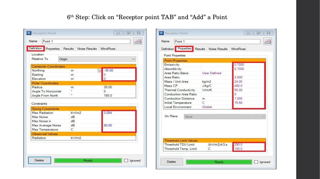
6th Step: Click on “Receptor point TAB” and “Add” a Point<br>
72
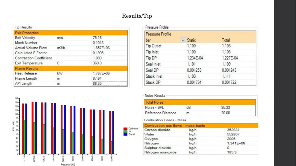
Results/Tip<br>
73
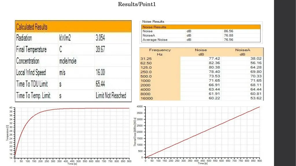
Results/Point1<br>
74
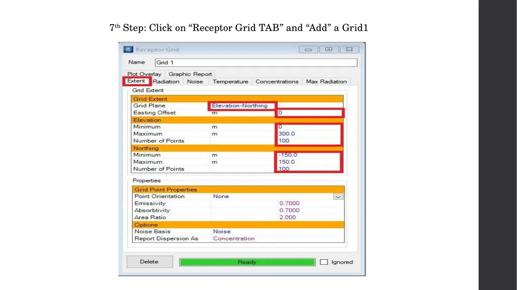
7th Step: Click on “Receptor Grid TAB” and “Add” a Grid1<br>
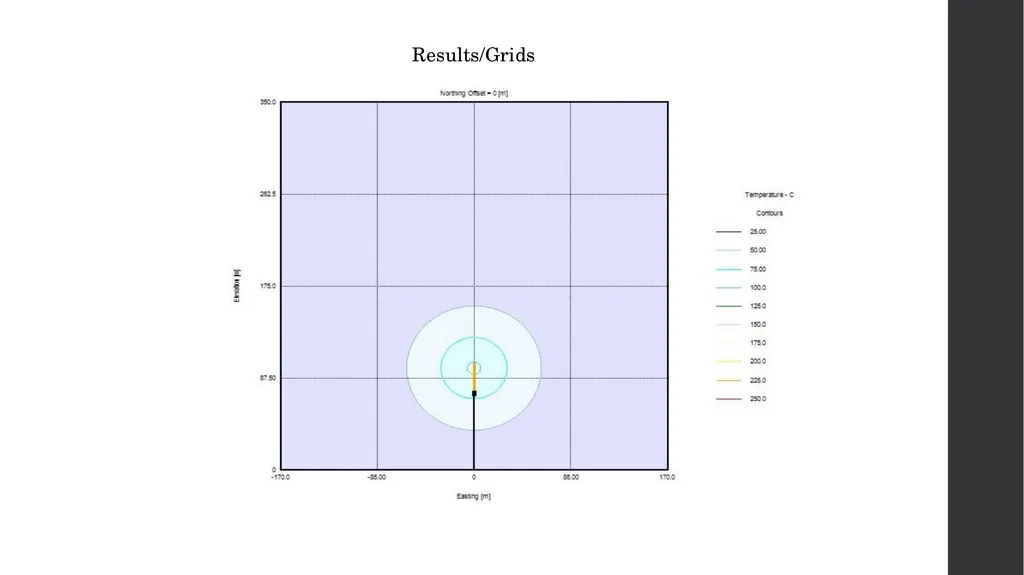
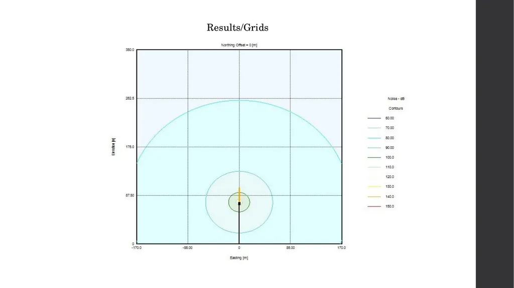
75
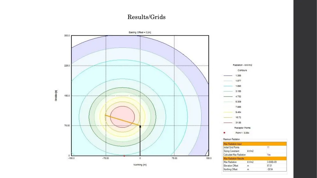
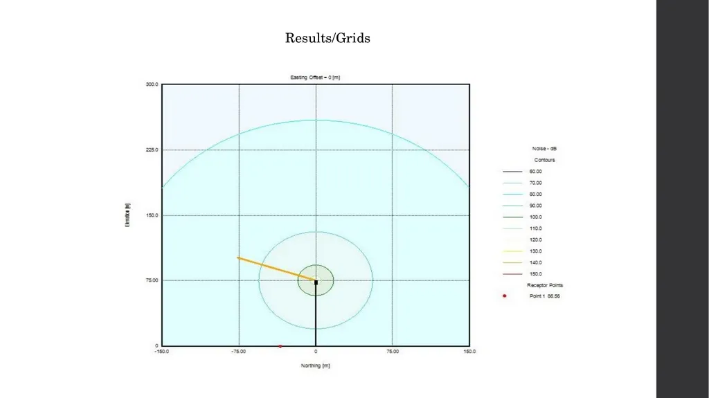
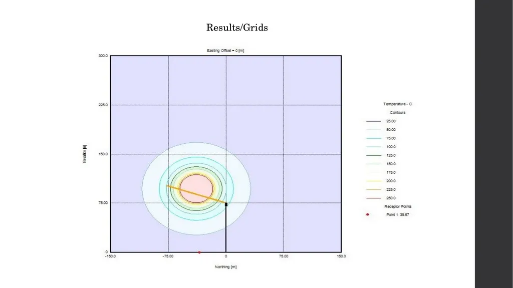
Results/Grids<br>
76
Results/Grids<br>
77
Results/Grids<br>
78
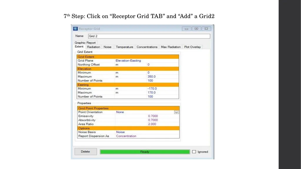
7th Step: Click on “Receptor Grid TAB” and “Add” a Grid2<br>
79
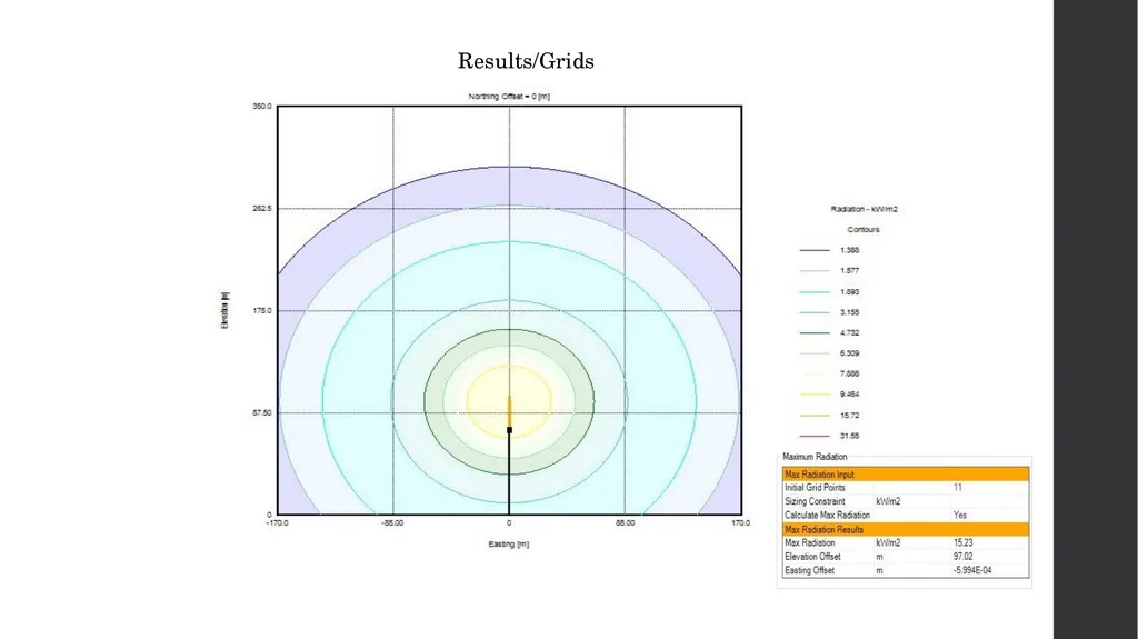
Results/Grids<br>
80
Results/Grids<br>
81
Results/Grids<br>
82
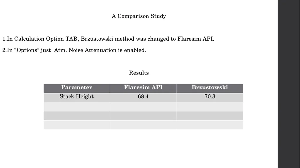
A Comparison Study
1.In Calculation Option TAB, Brzustowski method was changed to Flaresim API.
2.In “Options” just Atm. Noise Attenuation is enabled.
Results<br>
1.In Calculation Option TAB, Brzustowski method was changed to Flaresim API.
2.In “Options” just Atm. Noise Attenuation is enabled.
Results<br>
83
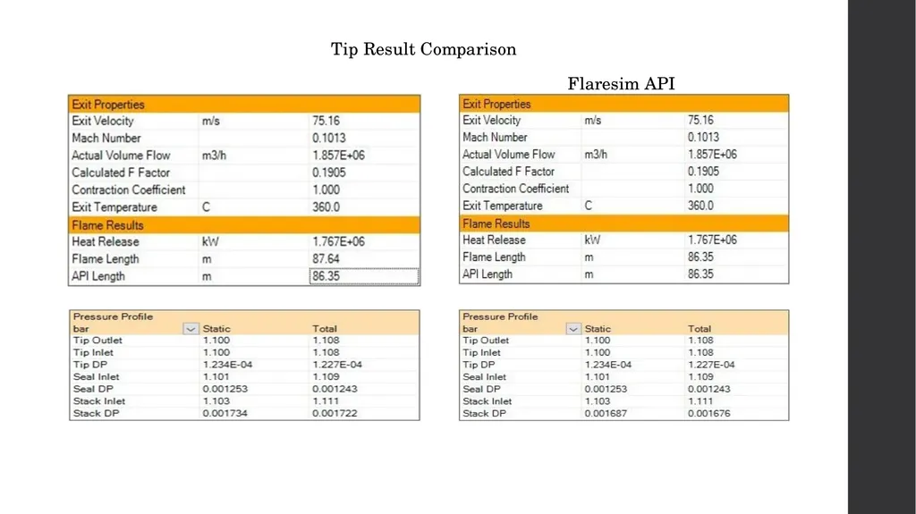
Tip Result Comparison
Flaresim API<br>
Flaresim API<br>
84
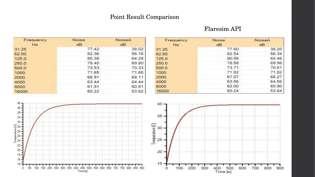
Point Result Comparison
Flaresim API<br>
Flaresim API<br>
85
Notes and Discussion
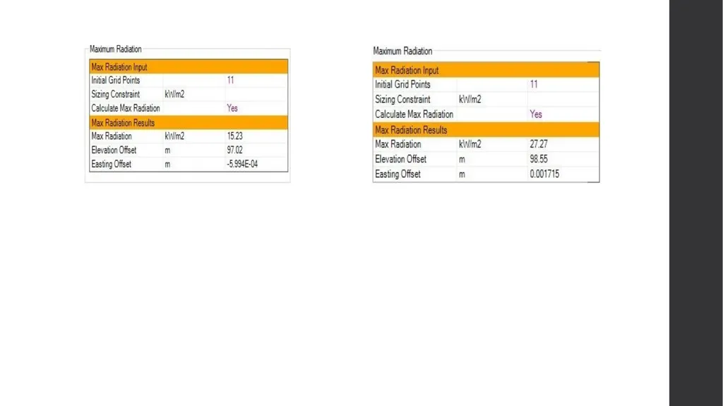
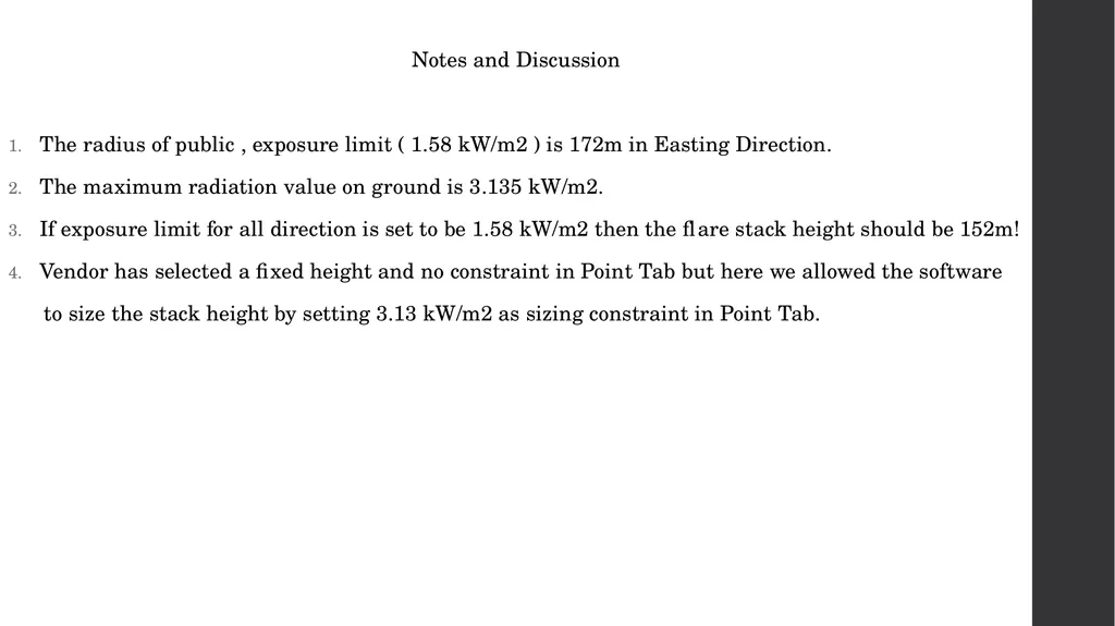
The radius of public , exposure limit ( 1.58 kW/m2 ) is 172m in Easting Direction.
The maximum radiation value on ground is 3.135 kW/m2.
If exposure limit for all direction is set to be 1.58 kW/m2 then the flare stack height should be 152m!
Vendor has selected a fixed height and no constraint in Point Tab but here we allowed the software
to size the stack height by setting 3.13 kW/m2 as sizing constraint in Point Tab.<br>
The radius of public , exposure limit ( 1.58 kW/m2 ) is 172m in Easting Direction.
The maximum radiation value on ground is 3.135 kW/m2.
If exposure limit for all direction is set to be 1.58 kW/m2 then the flare stack height should be 152m!
Vendor has selected a fixed height and no constraint in Point Tab but here we allowed the software
to size the stack height by setting 3.13 kW/m2 as sizing constraint in Point Tab.<br>
86
Flare Burner / Tip
In MEKPCO project, a steam-assisted flare tip is used to not only help the combustion be flameless but
also cool down the equipment.
The quantity of steam required for smokeless burning is a function of the gas composition, the flare
burner size and design, the steam-injector design and operating pressure, and the environmental
conditions. While steam assist enhances the combustion of relief gases that smoke, it adversely affects
the combustion of relief gases with a high level of inerts. Relief gases with a high level of inerts, when
flared from a steam-assisted flare, can require a greater calorific value to sustain the required flame
stability and hydrocarbon-destruction efficiency.
Flare tip length is normally between 3-5 meter. In MEKPCO project , pipe flare type is used due to low
Mach number.<br>
In MEKPCO project, a steam-assisted flare tip is used to not only help the combustion be flameless but
also cool down the equipment.
The quantity of steam required for smokeless burning is a function of the gas composition, the flare
burner size and design, the steam-injector design and operating pressure, and the environmental
conditions. While steam assist enhances the combustion of relief gases that smoke, it adversely affects
the combustion of relief gases with a high level of inerts. Relief gases with a high level of inerts, when
flared from a steam-assisted flare, can require a greater calorific value to sustain the required flame
stability and hydrocarbon-destruction efficiency.
Flare tip length is normally between 3-5 meter. In MEKPCO project , pipe flare type is used due to low
Mach number.<br>
87
Steam is often injected into the relief gas discharge at the top of a flare burner. Typically, a steam ring
that has a number of injection nozzles or slots is employed. The design and location of injector nozzles
varies as different flare manufacturers each have their own proprietary design.
The upper steam injection functions to inspirate air and to force the air mixture into the relief gas
discharging from the flare burner. The steam-injection pattern is intended to enhance fuel-air mixing
and can add to the momentum of the relief gas discharge. The steam and air acts to dilute the
hydrocarbon fuel content, which also reduces the smoking tendency. The steam vapor can also
participate in the combustion kinetics, assisting in the conversion of carbon to carbon monoxide.
The effective addition of steam from an upper steam ring increases the turbulence of combustion. The
overall noise level of the flare burner increases due to both the additional combustion noise and jet
noise from the steam nozzles. Steam-assisted, smokeless flares can have significantly increased overall
noise levels in comparison to flares with no steam assist.<br>
that has a number of injection nozzles or slots is employed. The design and location of injector nozzles
varies as different flare manufacturers each have their own proprietary design.
The upper steam injection functions to inspirate air and to force the air mixture into the relief gas
discharging from the flare burner. The steam-injection pattern is intended to enhance fuel-air mixing
and can add to the momentum of the relief gas discharge. The steam and air acts to dilute the
hydrocarbon fuel content, which also reduces the smoking tendency. The steam vapor can also
participate in the combustion kinetics, assisting in the conversion of carbon to carbon monoxide.
The effective addition of steam from an upper steam ring increases the turbulence of combustion. The
overall noise level of the flare burner increases due to both the additional combustion noise and jet
noise from the steam nozzles. Steam-assisted, smokeless flares can have significantly increased overall
noise levels in comparison to flares with no steam assist.<br>
88
The allowable flare burner exit velocity is a function of relief gas composition, flare burner design, and
the gas pressure available. These parameters are interrelated. Some flare tips incorporate a flame-
retention device or other means that provides a stable burning flame either attached or detached
relative to the flare tip. There is evidence that flame stability can be maintained at relatively high
velocities depending on the discharge properties and the type of tip used.
Experience has shown that a properly designed and applied flare burner can have an exit velocity of
more than Mach 0.5, if pressure drop, noise, and other factors permit. Many pipe flares, assisted or
unassisted, and air-assisted flares have been in service for many years with maximum Mach numbers
of Mach 0.8 and higher.<br>
the gas pressure available. These parameters are interrelated. Some flare tips incorporate a flame-
retention device or other means that provides a stable burning flame either attached or detached
relative to the flare tip. There is evidence that flame stability can be maintained at relatively high
velocities depending on the discharge properties and the type of tip used.
Experience has shown that a properly designed and applied flare burner can have an exit velocity of
more than Mach 0.5, if pressure drop, noise, and other factors permit. Many pipe flares, assisted or
unassisted, and air-assisted flares have been in service for many years with maximum Mach numbers
of Mach 0.8 and higher.<br>
89
Molecular Seal
Air seals (also called purge reduction or gas seals) prevent air from entering the stack, and are often
recommended to prevent flashbacks and explosions in a flare system.
Purge-reduction seals are not flame arrestors; that is, they will not stop a flashback. They are
designed as energy-conservation devices to reduce purge-gas flows required to mitigate air infiltration
into the stack.
Air present in the stack can create a potentially explosive mixture with incoming flare gas during
low-flare gas flow rate conditions.
There are two common types of mechanical seals, usually located at/or below the flare tip that are
used to reduce the amount of continuous purge gas required to prevent air infiltration into the flare
stack : molecular seals (sometimes called diffusion, buoyancy or labyrinth seals), and velocity (fluidic)
types.<br>
Air seals (also called purge reduction or gas seals) prevent air from entering the stack, and are often
recommended to prevent flashbacks and explosions in a flare system.
Purge-reduction seals are not flame arrestors; that is, they will not stop a flashback. They are
designed as energy-conservation devices to reduce purge-gas flows required to mitigate air infiltration
into the stack.
Air present in the stack can create a potentially explosive mixture with incoming flare gas during
low-flare gas flow rate conditions.
There are two common types of mechanical seals, usually located at/or below the flare tip that are
used to reduce the amount of continuous purge gas required to prevent air infiltration into the flare
stack : molecular seals (sometimes called diffusion, buoyancy or labyrinth seals), and velocity (fluidic)
types.<br>
90
In the event of loss of purge-gas flow (and assuming that there is no other waste-gas flow) the oxygen
level below the velocity type seal will almost immediately begin to increase. In the case of the buoyancy
seal there is a time delay between the moment the purge gas flow stops and the time the oxygen level
below the seal begins to increase.
The molecular seal consists of a baffled concentric cylinder arrangement, which uses the difference in
molecular weight of the flare gas and the ambient air to prevent air from entering the flare stack. This
seal normally reduces the purge-gas velocity required through the tip to 0,003 m/s (0,01 ft/s).<br>
level below the velocity type seal will almost immediately begin to increase. In the case of the buoyancy
seal there is a time delay between the moment the purge gas flow stops and the time the oxygen level
below the seal begins to increase.
The molecular seal consists of a baffled concentric cylinder arrangement, which uses the difference in
molecular weight of the flare gas and the ambient air to prevent air from entering the flare stack. This
seal normally reduces the purge-gas velocity required through the tip to 0,003 m/s (0,01 ft/s).<br>