MIXING Liquid mixing devices, vortex formation By Dr. Garima Joshi , Assistant Professor Dept of Pharm Sciences, MLSU, Udaipur B pharm III sem, Unit operations AIR JETS Air jets or other inert gas jets are effectively used for mixing
"MIXING – Liquid mixing devices, vortex formation" is the property of its rightful owner. Permission is granted to
download and print the materials on this website for personal, non-commercial use only, and to display it
on your personal computer provided you do not modify the materials and that you retain all copyright
notices contained in the materials. By downloading content from our website, you accept the terms of this
agreement.
Presentation Transcript
01
MIXING – Liquid mixing devices, vortex formation By Dr. Garima Joshi ,
Assistant Professor
Dept of Pharm Sciences, MLSU, Udaipur
B pharm III sem, Unit operations<br>
02
AIR JETS Air jets or other inert gas jets are effectively used for mixing purpose with fluid of the following characteristics;
Having low viscosity
Non foaming
Non-reactive with gas employed
Non-volatile in nature<br>
03
PRINCIPLE When compressed air jet or suitable gas is allows to pass at high pressure from the inlet provided at the bottom of the tank, air bubbles are formed in the liquid phase.
This causes buoyancy of the bubbles which lifts the liquid (confined to the central portion due to the presence of draft tubes) from bottom to the top of the vessel.
The liquids flow down from the periphery of the vessel and enter from the bottom due to suction effect.
The intense turbulence generated by the jet produces intimate mixing<br>
04
FLUID JETS FLUID JETS
In this device, the pumping operation is used to transfer the liquid into the mixing tank.
MECHANISM
In this case the fluids are pumped through nozzle which permits good circulation of material through the tank.
The fluid jets in this operation behaves like propeller in that they produce turbulent flow in the direction of their axis, while differ from propeller b/c they don't produce tangential flow themselves.
They may also operate simply by pumping the liquid from the tank and back into the tank through the jet.<br>
05
FLOW PATTERN DURING MIXING
Mixing occurs due to the resultant effect of 3 components acting on liquid:
Tangential / Circular component
Radial component
Axial / Longitudinal component
PITCH: distance covered by liquid during axial flow<br>
06
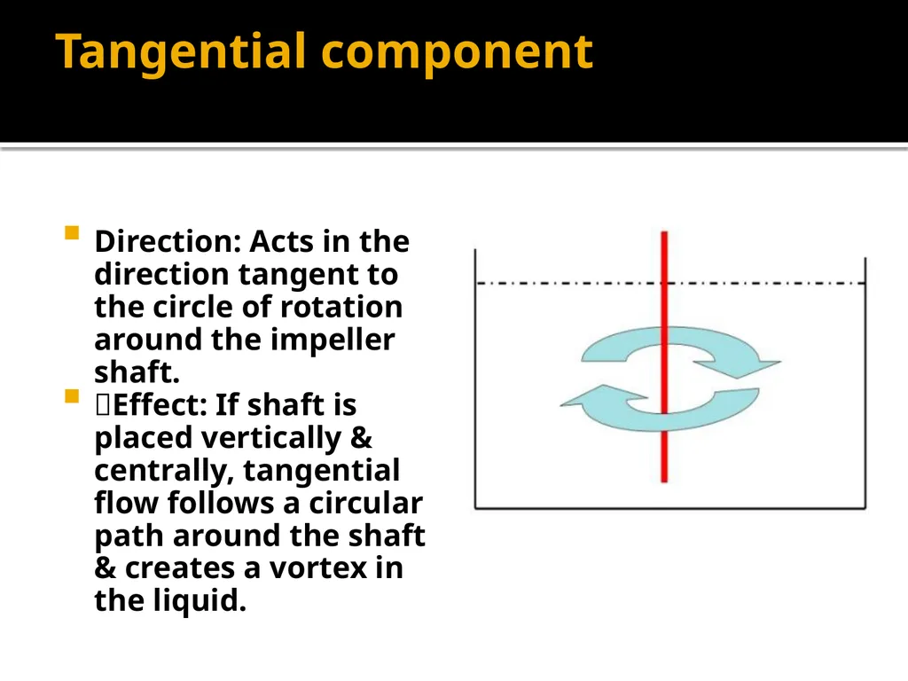
Tangential component Direction: Acts in the direction tangent to the circle of rotation around the impeller shaft.
Effect: If shaft is placed vertically & centrally, tangential flow follows a circular path around the shaft & creates a vortex in the liquid.<br>
07
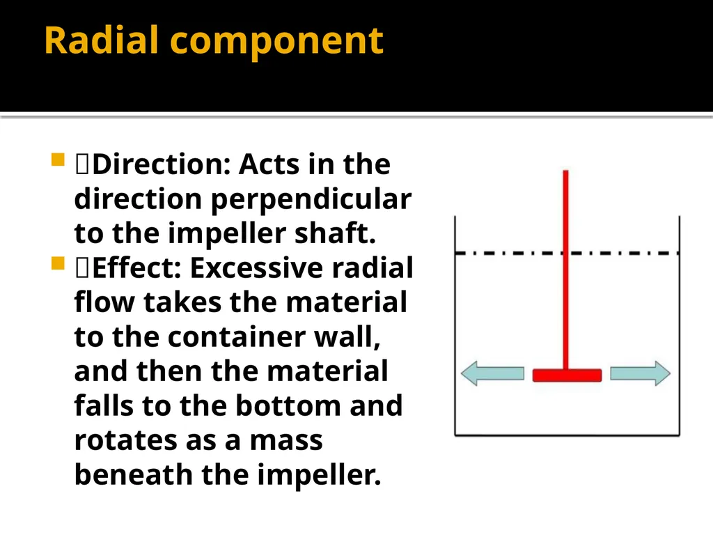
Radial component Direction: Acts in the direction perpendicular to the impeller shaft.
Effect: Excessive radial flow takes the material to the container wall, and then the material falls to the bottom and rotates as a mass beneath the impeller.<br>
08
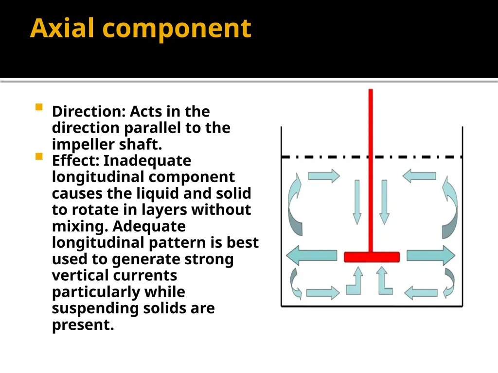
Axial component Direction: Acts in the direction parallel to the impeller shaft.
Effect: Inadequate longitudinal component causes the liquid and solid to rotate in layers without mixing. Adequate longitudinal pattern is best used to generate strong vertical currents particularly while suspending solids are present.<br>
09
VORTEX Formation Vortex is a powerful circular moving mass of water or wind that can draw object into its hollow which may result in air entrapped and bubbles formation.
If a low viscosity liquid is stirred in an un-baffled tank by an axially mounted agitator, tangential flow follows a circular path around the shaft & a swirling flow pattern is developed. This is vortex<br>
10
Reasons of vortex formation If the shaft is placed symmetrically in the tank.
If the blades of the turbines are arranged perpendicular to the central shaft.
At high impeller speeds
Unbaffledtank<br>
11
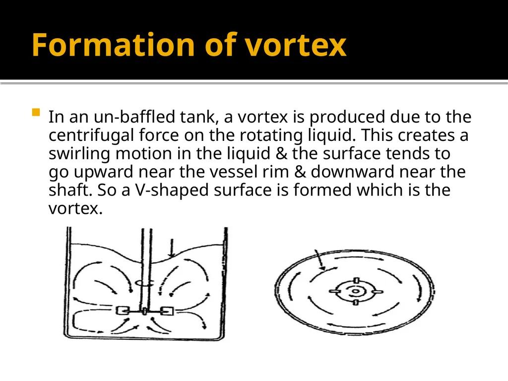
Formation of vortex In an un-baffled tank, a vortex is produced due to the centrifugal force on the rotating liquid. This creates a swirling motion in the liquid & the surface tends to go upward near the vessel rim & downward near the shaft. So a V-shaped surface is formed which is the vortex.<br>
12
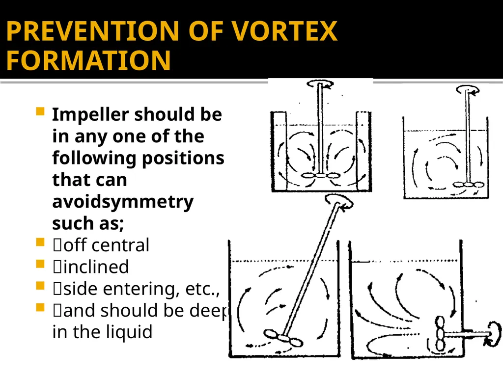
PREVENTION OF VORTEX FORMATION Impeller should be in any one of the following positions that can avoidsymmetry such as;
off central
inclined
side entering, etc.,
and should be deep in the liquid<br>
13
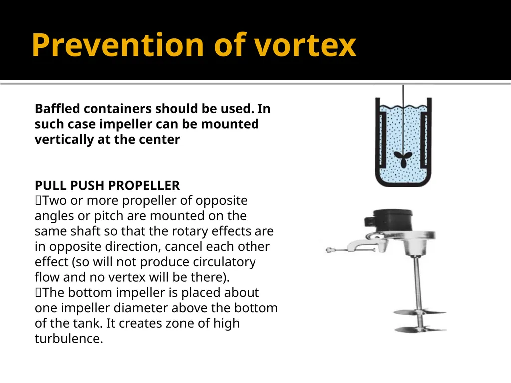
Prevention of vortex Baffled containers should be used. In such case impeller can be mounted vertically at the center PULL PUSH PROPELLER
Two or more propeller of opposite angles or pitch are mounted on the same shaft so that the rotary effects are in opposite direction, cancel each other effect (so will not produce circulatory flow and no vertex will be there).
The bottom impeller is placed about one impeller diameter above the bottom of the tank. It creates zone of high turbulence.<br>