04
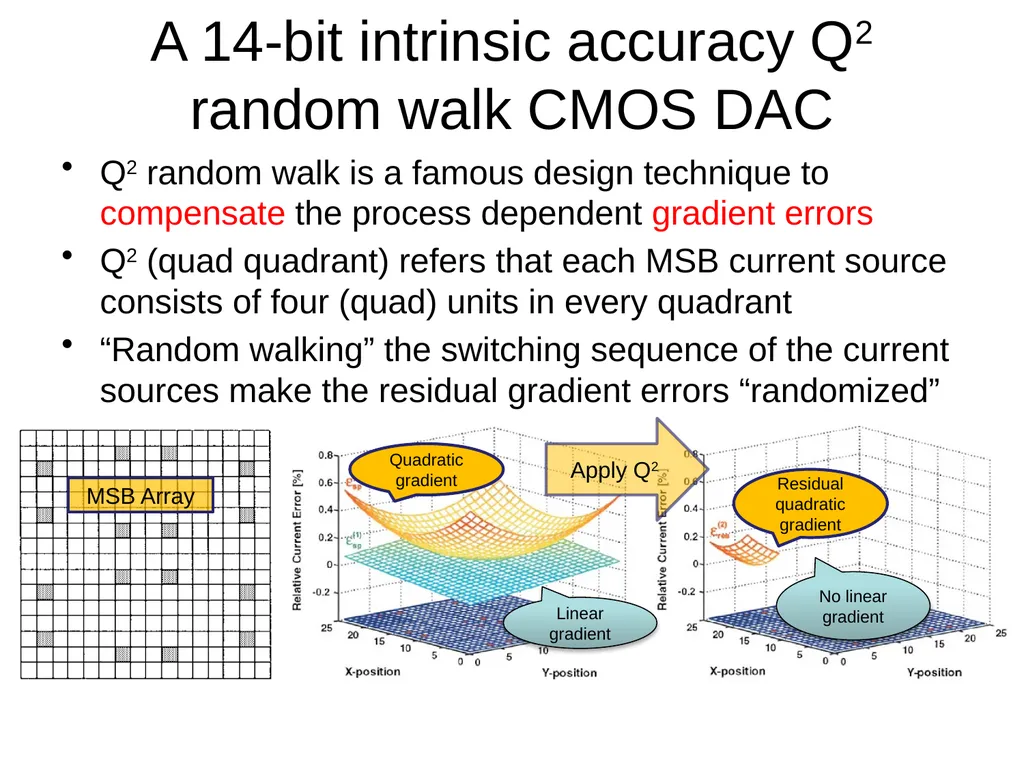
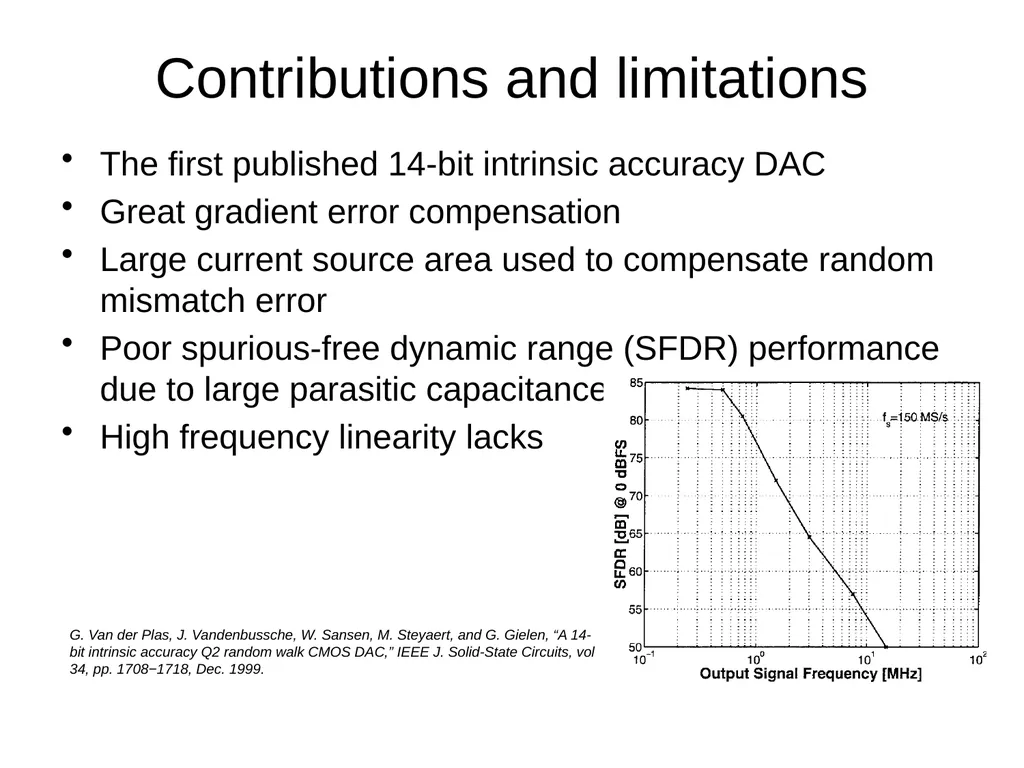
Contributions and limitations The first published 14-bit intrinsic accuracy DAC
Great gradient error compensation
Large current source area used to compensate random mismatch error
Poor spurious-free dynamic range (SFDR) performance due to large parasitic capacitance
High frequency linearity lacks G. Van der Plas, J. Vandenbussche, W. Sansen, M. Steyaert, and G. Gielen, “A 14-bit intrinsic accuracy Q2 random walk CMOS DAC,” IEEE J. Solid-State Circuits, vol 34, pp. 1708−1718, Dec. 1999.<br>
05
A self-trimming 14-b 100-MS/s CMOS DAC The self-trimming technique can effectively compensate the random mismatch error among current sources A. R. Bugeja, and B. Song, “A self-trimming 14-b 100-MS/s CMOS DAC,” IEEE J. Solid-State Circuits, vol 35, pp. 1841−1852, Dec. 2000.<br>
06
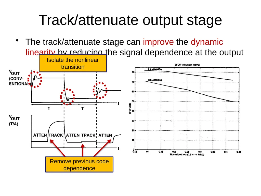
Track/attenuate output stage The track/attenuate stage can improve the dynamic linearity by reducing the signal dependence at the output Isolate the nonlinear transition Remove previous code dependence<br>
07
Contributions and limitations Great random mismatch error compensation by using self-trimming
Excellent dynamic linearity enhancement by the track/attenuate output stage
One of the best DACs in high frequency linearity performance
Complicated calibration loop (ADC-DSP-DAC)
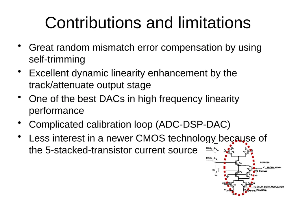
Less interest in a newer CMOS technology because of the 5-stacked-transistor current source<br>
08
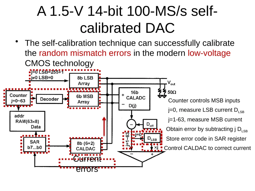
A 1.5-V 14-bit 100-MS/s self-calibrated DAC The self-calibration technique can successfully calibrate the random mismatch errors in the modern low-voltage CMOS technology Counter controls MSB inputs j=0, measure LSB current DLSB j=1-63, measure MSB current Obtain error by subtracting j DLSB Store error code in SAR register Control CALDAC to correct current Current errors<br>
09
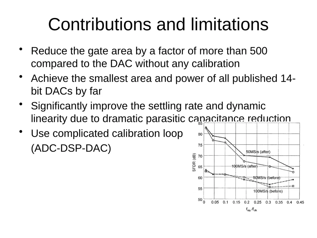
Contributions and limitations Reduce the gate area by a factor of more than 500 compared to the DAC without any calibration
Achieve the smallest area and power of all published 14-bit DACs by far
Significantly improve the settling rate and dynamic linearity due to dramatic parasitic capacitance reduction
Use complicated calibration loop
(ADC-DSP-DAC)<br>
10
A 14-bit 200-MHz current-steering DAC with switching-sequence post-adjustment The SSPA calibration can enhance the matching accuracy by adjusting the switching sequence of current sources after chip fabrication
It uses minimum analog circuits and some digital circuitry instead of the complicated ADC-DSP-DAC loop T. Chen, and G. Gielen, “A 14-bit 200-MHz current-steering DAC with switching-sequence post-adjustment calibration,” IEEE J. Solid-State Circuits, vol 42, pp. 2386−2394, Nov. 2007.<br>
11
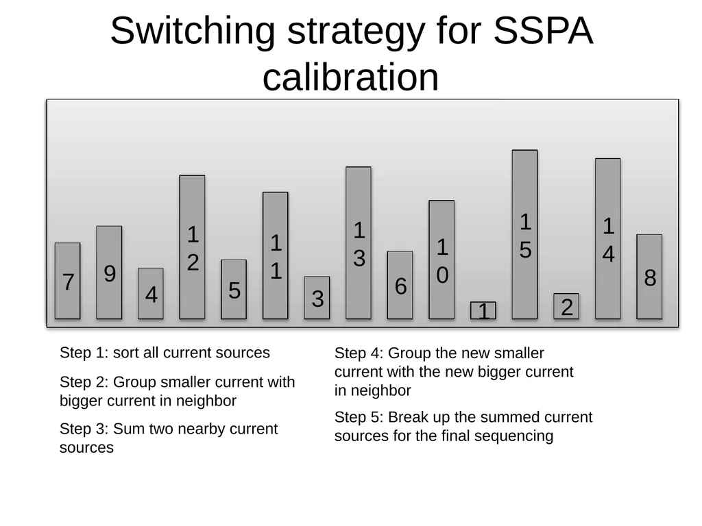
Switching strategy for SSPA calibration Step 1: sort all current sources Step 2: Group smaller current with bigger current in neighbor Step 3: Sum two nearby current sources Step 4: Group the new smaller current with the new bigger current in neighbor Step 5: Break up the summed current sources for the final sequencing<br>
12
Contributions and limitations Make the area of current sources only 10% of area required by an intrinsic accuracy DAC
Substantiate the potential of calibrating a DAC with good performance by using only minimum requirement of analog circuits and some digital circuitry
Static performance is not as
good as previous technique
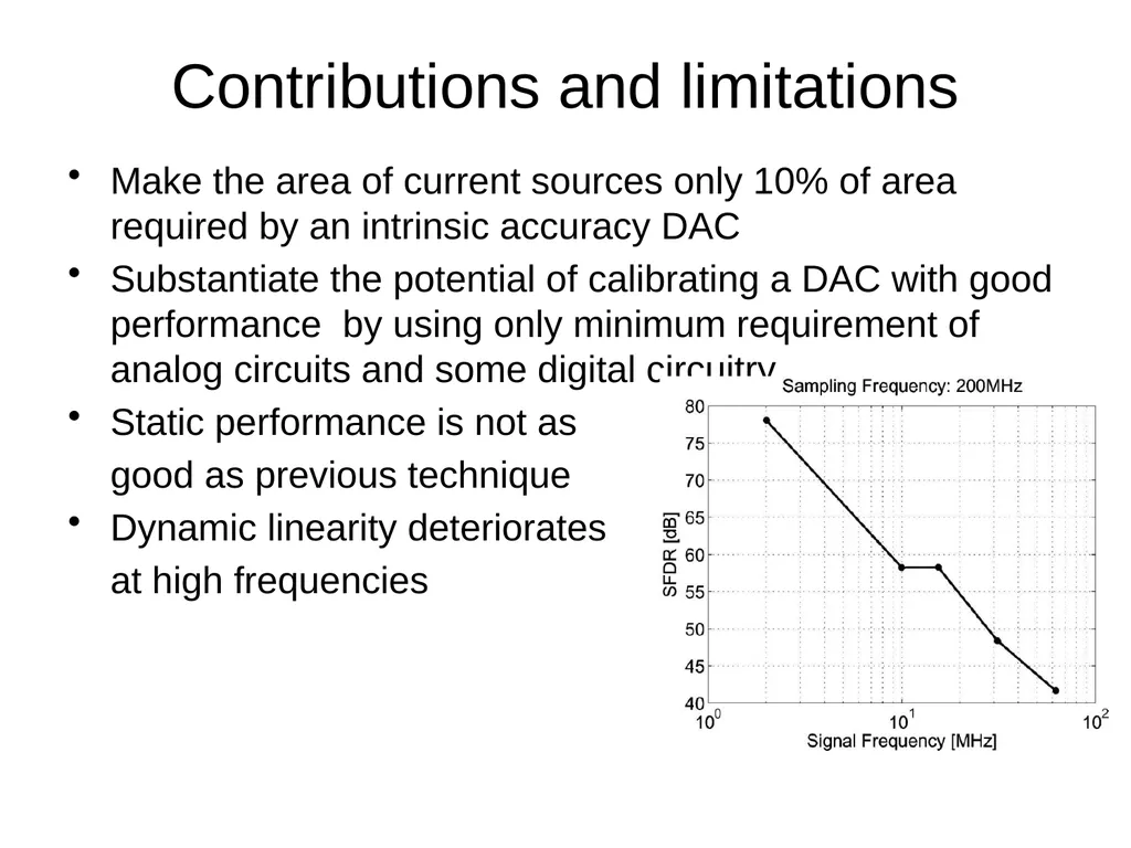
Dynamic linearity deteriorates
at high frequencies<br>
13
A 12 bit 2.9 GS/s DAC with IM3 < -60 dBc beyond 1 GHz in 65 nm CMOS This DAC design extends the 70dB and 60dB SFDR bandwidths to 225MHz and 550 MHz with fsamp > 1GS/s
They recognize the fact that the switching output impedance is a major error source to the DAC’s output distortion
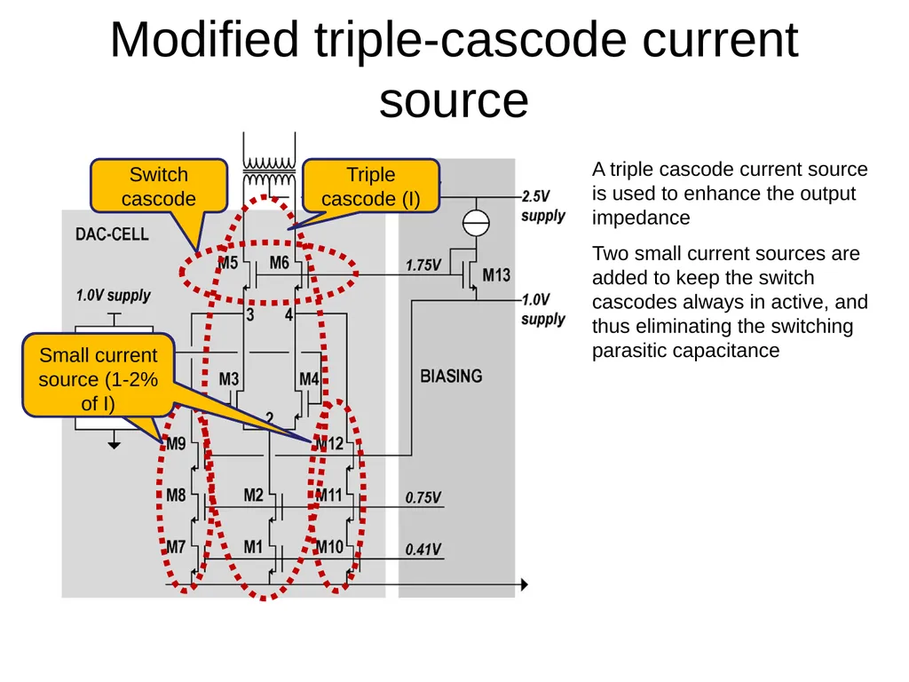
Modified triple-cascode current source is used to improve the dynamic linearity C.-H. Lin, F.M.I. van der Goes, J. R. Westra, J. Mulder, Y. Lin, E. Arslan, E. Ayranci, X. Liu, and K. Bult, “A 12 bit 2.9 GS/s DAC with IM3 < 60 dBc beyond 1 GHz in 65 nm CMOS,” IEEE J. Solid-State Circuits, vol 44, pp. 3285−3293, Dec. 2009.<br>
14
Modified triple-cascode current source A triple cascode current source is used to enhance the output impedance Two small current sources are added to keep the switch cascodes always in active, and thus eliminating the switching parasitic capacitance Switch cascode Small current source Small current source (1-2% of I) Triple cascode (I)<br>
15
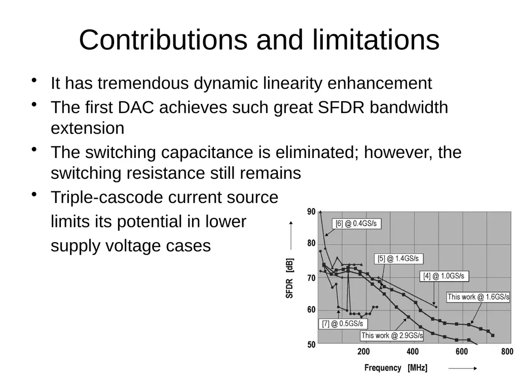
Contributions and limitations It has tremendous dynamic linearity enhancement
The first DAC achieves such great SFDR bandwidth extension
The switching capacitance is eliminated; however, the switching resistance still remains
Triple-cascode current source
limits its potential in lower
supply voltage cases<br>
16
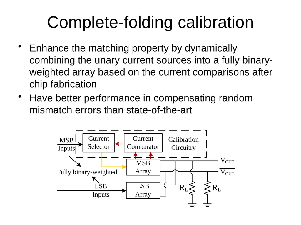
Complete-folding calibration Enhance the matching property by dynamically combining the unary current sources into a fully binary-weighted array based on the current comparisons after chip fabrication
Have better performance in compensating random mismatch errors than state-of-the-art<br>
17
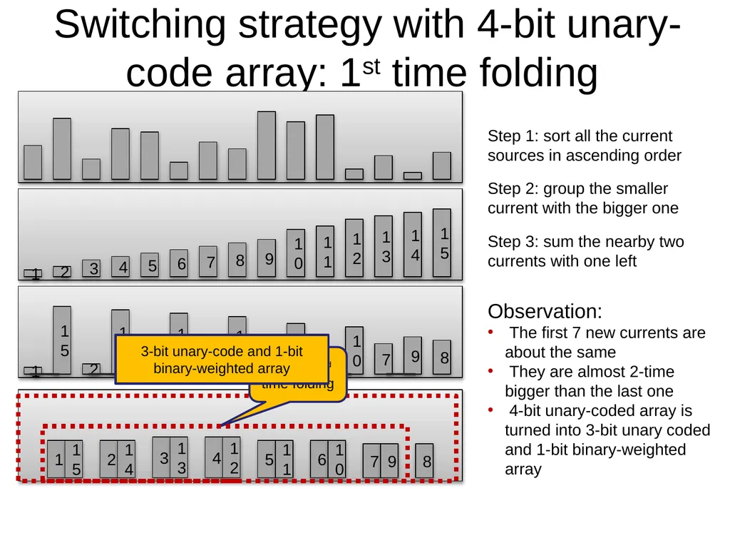
Switching strategy with 4-bit unary-code array: 1st time folding Step 1: sort all the current sources in ascending order Step 2: group the smaller current with the bigger one Step 3: sum the nearby two currents with one left Observation:
The first 7 new currents are about the same
They are almost 2-time bigger than the last one
4-bit unary-coded array is turned into 3-bit unary coded and 1-bit binary-weighted array Use for 2nd time folding 3-bit unary-code and 1-bit binary-weighted array<br>
18
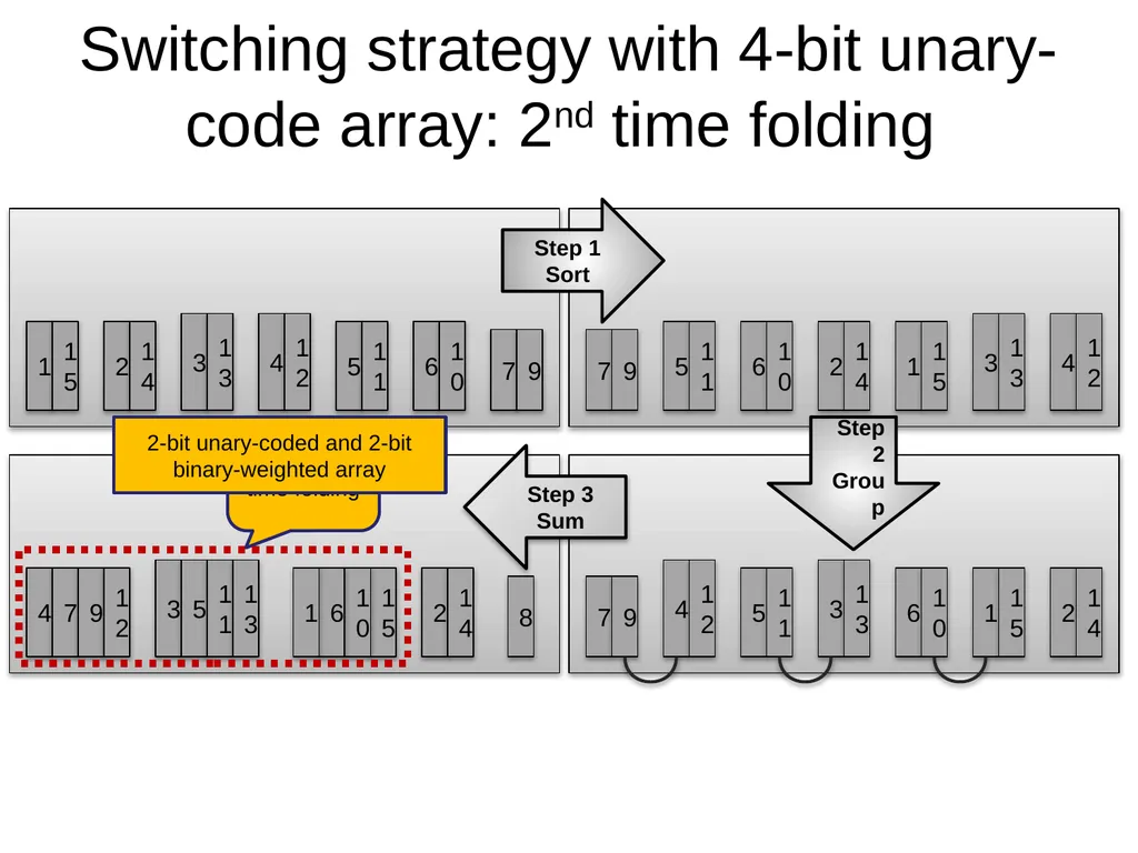
Switching strategy with 4-bit unary-code array: 2nd time folding Step 1 Sort Step 2 Group Step 3 Sum Use for 3rd time folding 2-bit unary-coded and 2-bit binary-weighted array<br>
19
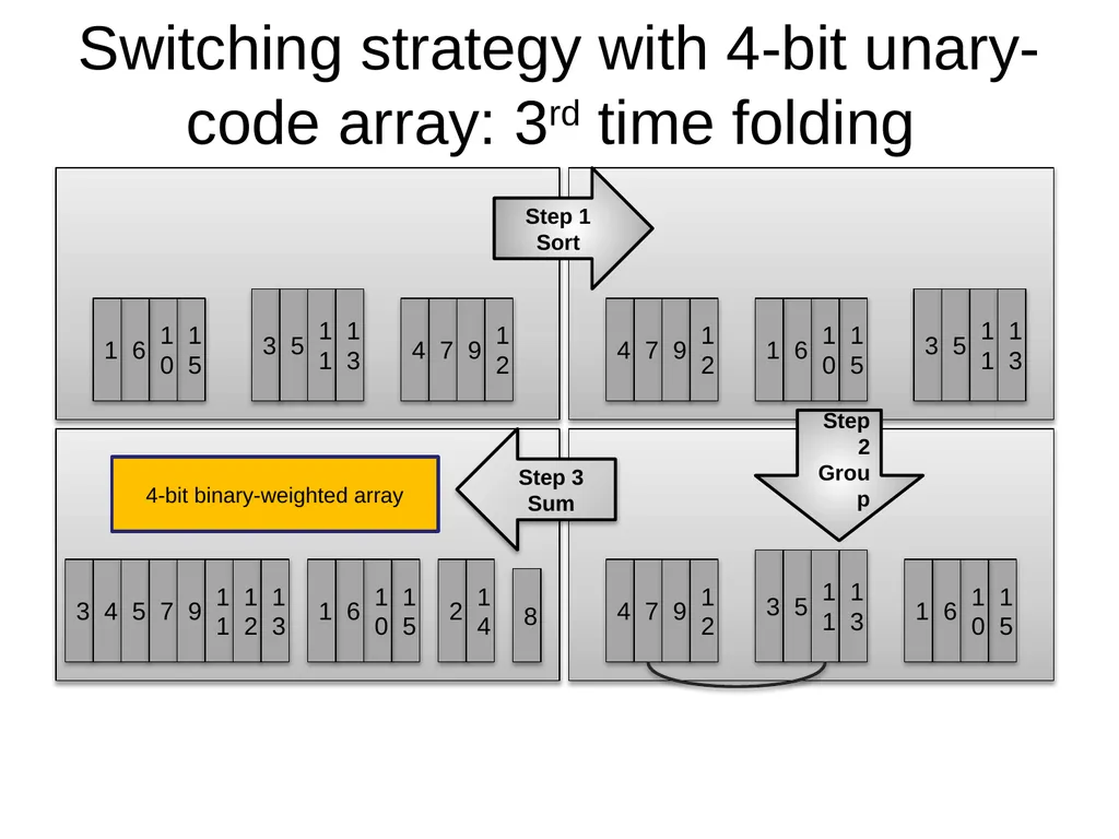
Switching strategy with 4-bit unary-code array: 3rd time folding Step 1 Sort Step 2 Group Step 3 Sum 4-bit binary-weighted array<br>
20
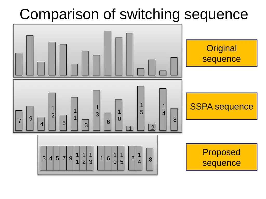
Comparison of switching sequence Original sequence SSPA sequence Proposed sequence<br>
21
General switching strategy An n-bit unary-coded array can be converted into an (n-1)-bit unary-coded array with 1-bit binary-weighted array by 1-time single-folding
Example: 1-time single-folding can convert a 4-bit unary-coded array into a 3-bit unary-coded and 1-bit binary-weighted
Complete-folding is to implement (n-1)-time single-folding in an n-bit unary-coded array
Example: A 4-bit unary-coded array needs 3-time single-folding to ensure complete-folding calibration<br>
22
Statistical simulation setup 10,000 14-bit current-steering DAC behavioral models were randomly generated
7-bit unary-coded MSB array
7-bit binary-weighted LSB array
Implement 3 calibration techniques separately in the MSB array to compare results
SSPA Calibration + 20 statistical outlier elimination
Self Calibration
Complete-folding Calibration + 20 statistical outlier elimination
The LSB array is realized by intrinsic-accuracy method<br>
23
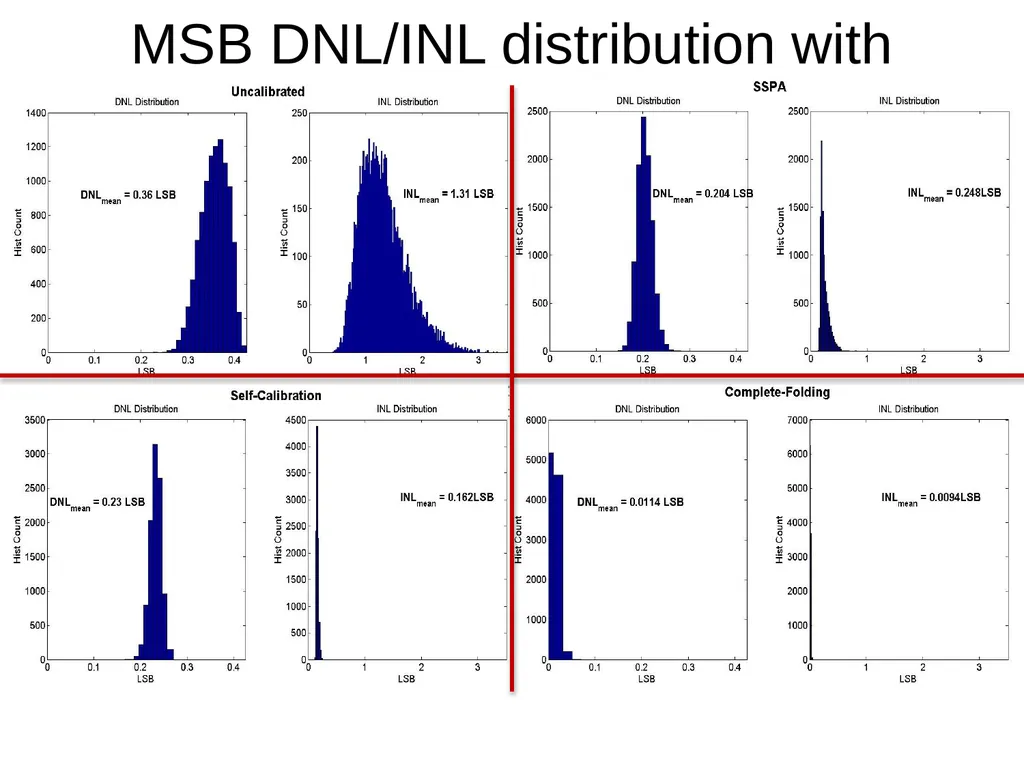
MSB DNL/INL distribution with different calibration techniques<br>