
Occupational Specialism: Gas Engineering K1.28



Description: Occupational Specialism: Gas Engineering K1.28 Fault-finding techniques, their suitability for different situations and how they are applied in practice PowerPoint 1.28a: Introduction to fault-finding and the diagnostic process Starter A
Related Topics
Download Presentation
"Occupational Specialism: Gas Engineering K1.28" is the property of its rightful owner. Permission is granted to download and print the materials on this website for personal, non-commercial use only, and to display it on your personal computer provided you do not modify the materials and that you retain all copyright notices contained in the materials. By downloading content from our website, you accept the terms of this agreement.
Presentation Transcript
slide1. Occupational Specialism: Gas Engineering
K1.28 Fault-finding techniques, their suitability for different situations and how they are applied in practice
PowerPoint 1.28a: Introduction to fault-finding and the diagnostic process<br>
slide2. Starter A customer says their boiler keeps locking out after running hot water. There are no visible leaks or error codes. Where would you begin fault-finding?
Discuss:
What questions would you ask the user?
What would you check first — visually or with a tool?
What safety steps must come before touching anything?<br>
slide3. Objective By the end of this session, you should be able to:
Describe the fault-finding process and its stages.
Explain the importance of safe isolation procedures.
Identify the role of manufacturer documentation and user questioning.
Apply a structured method to select suitable diagnostic techniques.<br>
slide4. What is fault-finding? Fault-finding in gas engineering is a systematic method to identify appliance or system faults.
It relies on a careful approach using various techniques to pinpoint issues while prioritising safety.
Proper documentation is essential for Gas Safe Register compliance and tracking diagnostic steps.<br>
slide5. What is fault-finding? Key components
Visual inspection techniques
User feedback collection
Systematic testing procedures
Reference to manufacturer instructions (MI)
Use of appropriate test equipment<br>
slide6. What is fault-finding? Core principles
Must be carried out safely
Follow a logical sequence
Maintain clear records
Verify results through testing
Follow manufacturer guidelines<br>
slide7. The diagnostic process: step-by-step 1. Gather information
Question the user about fault symptoms
Check for error codes on display
Note visual signs of malfunction
Review service history if available<br>
slide8. The diagnostic process: step-by-step 2. Risk assess and isolate
Assess safety risks before proceeding
Perform electrical isolation
Perform gas isolation as required
Document isolation procedures<br>
slide9. The diagnostic process: step-by-step 3. Inspect visually
Look for obvious damage
Check for water leaks or staining
Inspect for burnt components
Check flue condition and integrity<br>
slide10. The diagnostic process: step-by-step 4. Carry out tests
Gas pressure testing
Electrical resistance checks
Voltage measurements
Continuity testing<br>
slide11. The diagnostic process: step-by-step 5. Interpret results
Compare readings to MI specifications
Identify out-of-range values
Determine the root cause of the fault
Document all findings<br>
slide12. The diagnostic process: step-by-step 6. Take corrective action
Replace faulty components
Clean or adjust as needed
Report unresolvable issues
Advise customer of repairs needed<br>
slide13. The diagnostic process: step-by-step 7. Verify and recommission
Retest after repairs
Recommission the appliance
Complete paperwork
Demonstrate to the customer<br>
slide14. Safe isolation procedures Before conducting any fault-finding activities, proper isolation procedures must be followed to ensure safety.
These procedures are not optional and represent a critical requirement under Gas Safe Register guidelines.<br>
slide15. Safe isolation procedures Step 1: Working environment Confirm with the designated authority that isolating the equipment or circuit is permitted and that shutting down any other electrical devices connected to the circuit is acceptable.
Step 2: Safe to touch (equipment) Choose a suitable no-contact voltage detector. Ensure the device is free from damage and test it on a proving device or a known live source. All testing instruments should be proprietary designs and comply with BS EN 61010-31, BS EN 615572, or BS EN 61243-3 standards.<br>
slide16. Safe isolation procedures Non-contact live circuit detectors (voltage sticks):
Following multiple fatalities over time, it has become standard practice in the gas industry to employ single-pole or non-contact live circuit detectors, often called voltage sticks.
These devices are used before handling appliance casings, gas, and water pipes to verify that no hazardous voltage is present as a result of a fault.<br>
slide17. Safe isolation procedures HSE Guidance Note GS38
(Electrical test equipment for use on low voltage electrical systems, fourth edition).
Specifies that no-contact live circuit detectors (voltage sticks) are intended solely for detecting live equipment and should not be relied upon to confirm that equipment is de-energised.
As a result, additional suitable tests are required to verify that the equipment is electrically dead before any work begins.<br>
slide18. Safe isolation procedures Step 3: Safe-to-touch (procedure)
Use the no-contact voltage detector to perform a sweeping scan of all exposed surfaces of the appliance casing and all exposed metal pipework, both connected to and in close proximity to the appliance/gas meter installation.
If the no-contact voltage detector indicates the presence of voltage, stop the procedure immediately and inform the customer that the installation requires the immediate attention of a suitably electrically competent person.<br>
slide19. Safe isolation procedures Step 3: Safe-to-touch (procedure)
If a fault is detected, the engineer must perform a risk assessment or consult an electrical expert to ensure safety.
If the no-contact voltage detector shows no voltage on the appliance or nearby pipework, test the device on a live 13A socket to confirm it detects 230V by sound or light.<br>
slide20. Safe isolation procedures Steps 4–8: Safe isolation
Identify the appliance's isolation point and verify that a GS 38-approved two-pole voltage indicator is working.
Confirm the appliance is functional and powered by one source.
Isolate by turning off the circuit at the SFCU, unplugging, removing the fuse, or switching off the MCB.
Apply a lock-off device and warning label, keeping the key.
Ensure all terminals are dead, and for TT earthing systems, isolate all live conductors, including neutral.<br>
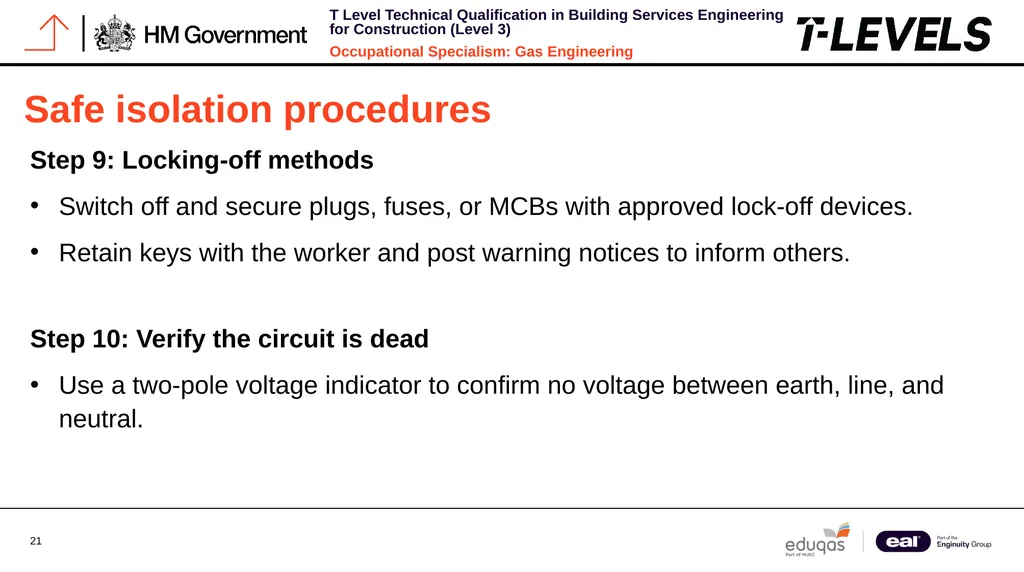
slide21. Safe isolation procedures Step 9: Locking-off methods
Switch off and secure plugs, fuses, or MCBs with approved lock-off devices.
Retain keys with the worker and post warning notices to inform others.
Step 10: Verify the circuit is dead
Use a two-pole voltage indicator to confirm no voltage between earth, line, and neutral.<br>
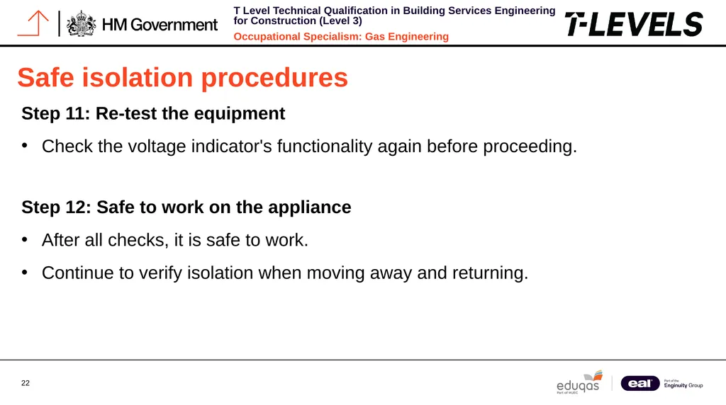
slide22. Safe isolation procedures Step 11: Re-test the equipment
Check the voltage indicator's functionality again before proceeding.
Step 12: Safe to work on the appliance
After all checks, it is safe to work.
Continue to verify isolation when moving away and returning.<br>
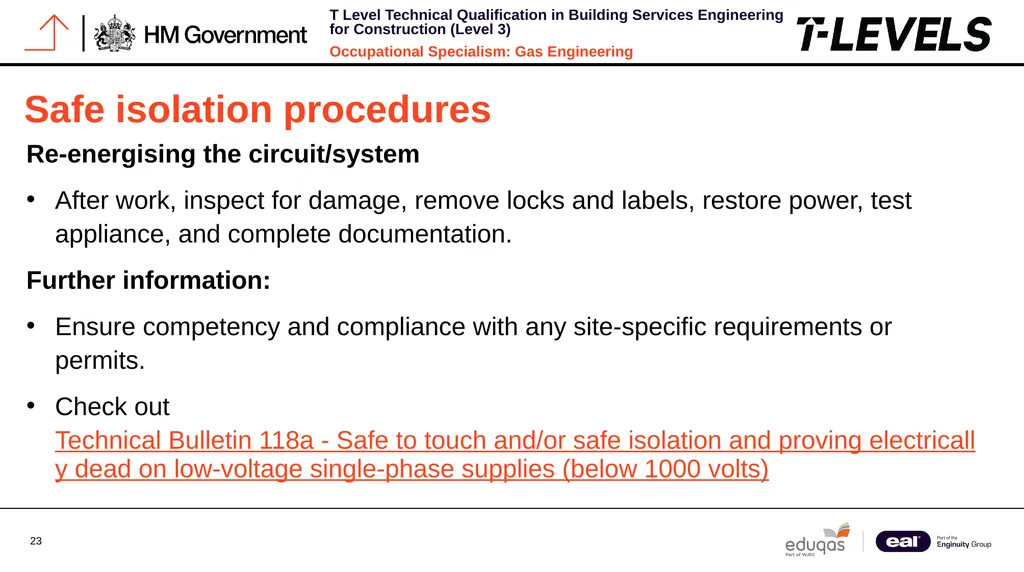
slide23. Safe isolation procedures Re-energising the circuit/system
After work, inspect for damage, remove locks and labels, restore power, test appliance, and complete documentation.
Further information:
Ensure competency and compliance with any site-specific requirements or permits.
Check out Technical Bulletin 118a - Safe to touch and/or safe isolation and proving electrically dead on low-voltage single-phase supplies (below 1000 volts)<br>
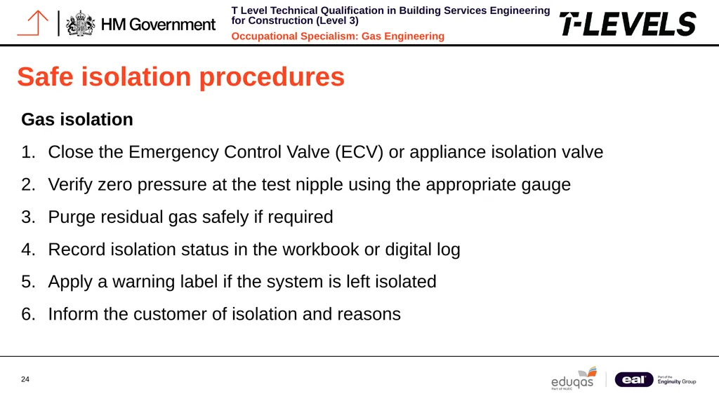
slide24. Safe isolation procedures Gas isolation
Close the Emergency Control Valve (ECV) or appliance isolation valve
Verify zero pressure at the test nipple using the appropriate gauge
Purge residual gas safely if required
Record isolation status in the workbook or digital log
Apply a warning label if the system is left isolated
Inform the customer of isolation and reasons<br>
slide25. Safe isolation procedures Never attempt fault-finding on live electrical circuits or pressurised gas systems.
Failure to properly isolate before work is a breach of safety regulations and may result in serious injury or death.<br>
slide26. Questioning the customer Asking effective questions is an essential diagnostic technique that can save considerable time and help identify problem areas before any physical examination starts.
Customers' answers often provide important hints about intermittent problems that might not appear during your visit.
Make sure to document customer responses in your workbook since they serve as part of your diagnostic record and could be necessary for warranty claims or compliance purposes.
Avoid leading questions that may prompt customers to give answers they believe you want instead of truthful information.<br>
slide27. Questioning the customer Event details
What was happening when the fault first occurred?
Was there anything unusual (sounds, smells, etc.)?
What time of day does it typically happen?
Fault pattern
Is the problem constant or intermittent?
Does it happen after specific actions?
How long has this been occurring?<br>
slide28. Questioning the customer History and changes
Have they had similar issues before?
Any recent changes to property or usage?
Has anyone else worked on the appliance?<br>
slide29. Reading manufacturer fault charts Manufacturer Instructions (MIs) include detailed fault-finding charts designed to offer structured methods for diagnosing particular appliance problems.
These charts are mandatory references to consult during any fault-finding process.
Usually formatted as flowcharts, manufacturer fault charts lead you through a logical series of tests depending on the symptoms observed.
They often specify expected component test values unique to the appliance model.<br>
slide30. Reading manufacturer fault charts Many modern appliances now incorporate QR codes that connect to online versions of fault charts, which are often more current than the printed manuals provided with the appliance.<br>
slide31. Reading manufacturer fault charts Key components of fault charts
Error codes and their meanings
Diagnostic LED patterns
Expected sensor resistance values
Voltage test points
Component location diagrams
Step-by-step testing procedures<br>
slide32. Reading manufacturer fault charts Using fault charts correctly
Follow the sequence exactly as shown
Never skip steps or make assumptions
Document all readings taken
Use specified test equipment only
Compare results with specified ranges
Never bypass the manufacturer's recommended fault-finding sequence. Doing so may lead to misdiagnosis, unnecessary parts replacement, or creation of dangerous conditions.<br>
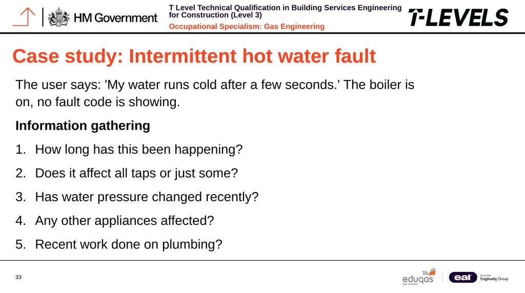
slide33. Case study: Intermittent hot water fault The user says: 'My water runs cold after a few seconds.' The boiler is on, no fault code is showing.
Information gathering
How long has this been happening?
Does it affect all taps or just some?
Has water pressure changed recently?
Any other appliances affected?
Recent work done on plumbing?<br>
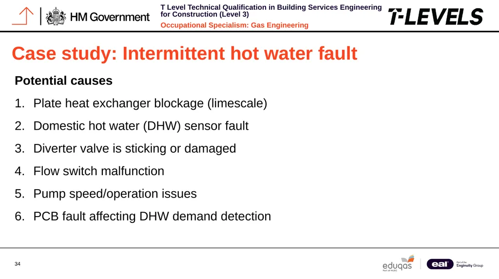
slide34. Case study: Intermittent hot water fault Potential causes
Plate heat exchanger blockage (limescale)
Domestic hot water (DHW) sensor fault
Diverter valve is sticking or damaged
Flow switch malfunction
Pump speed/operation issues
PCB fault affecting DHW demand detection<br>
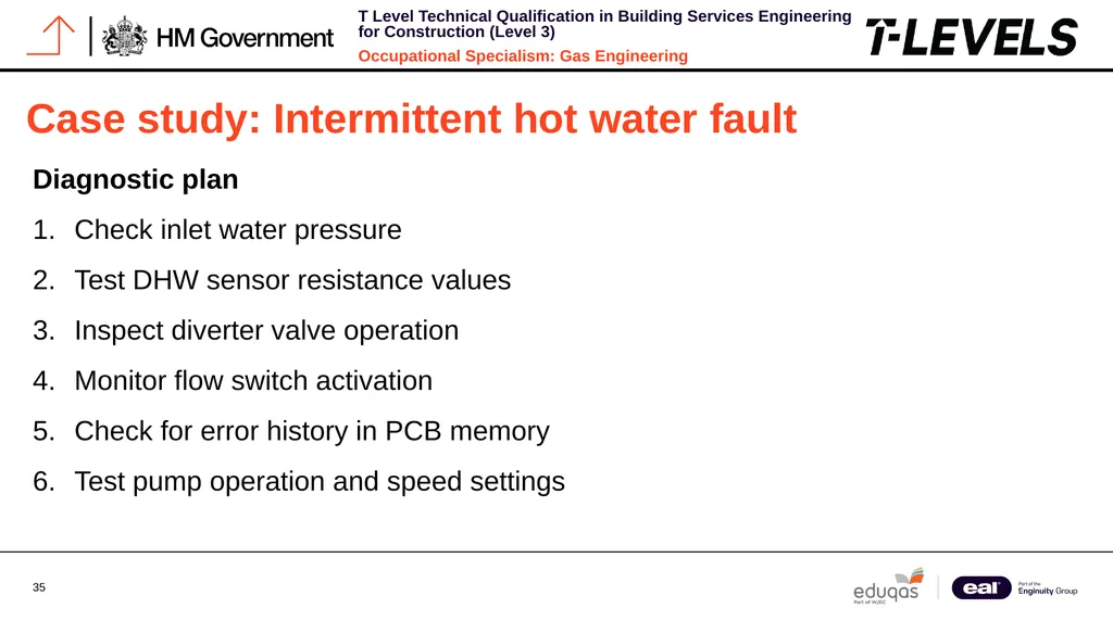
slide35. Case study: Intermittent hot water fault Diagnostic plan
Check inlet water pressure
Test DHW sensor resistance values
Inspect diverter valve operation
Monitor flow switch activation
Check for error history in PCB memory
Test pump operation and speed settings<br>
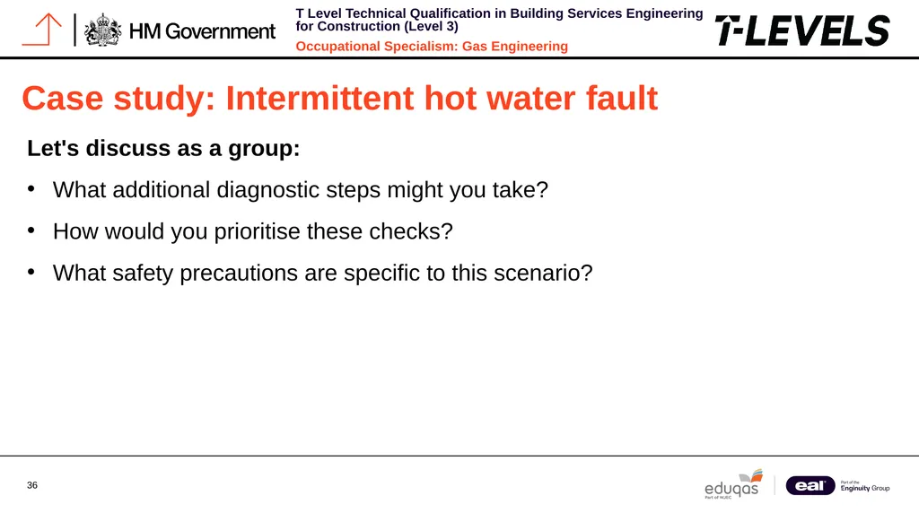
slide36. Case study: Intermittent hot water fault Let's discuss as a group:
What additional diagnostic steps might you take?
How would you prioritise these checks?
What safety precautions are specific to this scenario?<br>
slide37. The importance of pressure testing Pressure testing is fundamental to gas appliance fault-finding.
Incorrect gas pressure is a common cause of operational issues and can lead to dangerous conditions if not properly checked and rectified.
Working pressure, standing pressure and burner pressure all provide valuable diagnostic information.
Each measurement has specific test points and expected values that must be checked against manufacturer specifications.<br>
slide38. The importance of pressure testing Modern pressure gauges often feature digital displays with data logging capabilities, allowing for more precise readings and the ability to monitor pressure fluctuations over time.
These tools are invaluable for diagnosing intermittent pressure-related faults.<br>
slide39. The importance of pressure testing Standing pressure
Measured with appliance off
Indicates supply pressure to the property
Typically 21 mbar for natural gas
Low reading suggests supply issues<br>
slide40. The importance of pressure testing Working pressure
Measured with appliance running
Should not drop more than 1 mbar from standing
Significant drop indicates pipework restrictions
Must be documented on benchmark<br>
slide41. Quick knowledge check Which step comes first in the fault-finding process?
Test the electrodes
Check the MI fault chart
Ask the customer questions
Turn the appliance back on<br>
slide42. Quick knowledge check Correct answer: C) Ask the customer questions
The fault-finding process should always begin with gathering information.
Customer questioning provides valuable context about the fault before any technical investigation begins.
This initial step helps focus your diagnostic efforts and can save significant time by identifying patterns or potential external factors affecting the appliance.<br>
slide43. Electrical testing fundamentals Electrical fault-finding is essential for diagnosing modern gas appliances, which rely heavily on electronic controls and sensors.
Understanding how to properly use electrical testing equipment is a core competency for gas engineers.
When testing electrical components, always refer to manufacturer documentation for the specific resistance, voltage, or continuity values expected.
These can vary significantly between appliance models and manufacturers.<br>
slide44. Electrical testing fundamentals Recording your electrical test results provides documentation of the fault-finding process and may be required for warranty claims or compliance with Gas Safe Register requirements.<br>
slide45. Electrical testing fundamentals Continuity testing
Used to check for breaks in circuits
Tests fuses, wiring, and connections
Set meter to continuity/resistance mode
Zero reading indicates good continuity<br>
slide46. Electrical testing fundamentals Resistance testing
Checks sensors and thermistors
Set meter to ohms (Ω) scale
Compare to MI specifications
NTC sensors decrease resistance when hot<br>
slide47. Electrical testing fundamentals Voltage testing
Confirms power to components
Set meter to AC/DC voltage as appropriate
Always test with circuit powered
Compare to expected values in MI
Always ensure electrical isolation before connecting test leads to components for resistance or continuity testing. Voltage testing must be performed with extreme caution on live circuits.<br>
slide48. Common fault patterns in combination boilers Combination boilers exhibit certain fault patterns that experienced engineers learn to recognise.
Understanding these common fault signatures can significantly speed up the diagnostic process.
While these patterns provide useful starting points, always follow the manufacturer's diagnostic procedures rather than relying solely on past experience.
Similar symptoms can have different causes in different appliance models.<br>
slide49. Common fault patterns in combination boilers Intermittent lockouts
Flame detection issues
Electrode gaps incorrect
Condensate blockage
Fan speed fluctuations
Gas valve operation issues<br>
slide50. Common fault patterns in combination boilers No hot water
Diverter valve failure
DHW flow switch issues
Plate heat exchanger blockage
DHW sensor failure
PCB communication problems<br>
slide51. Common fault patterns in combination boilers No central heating
Pump failure or blockage
System pressure loss
CH sensor fault
PCB relay failure
Programmer/timer issues<br>
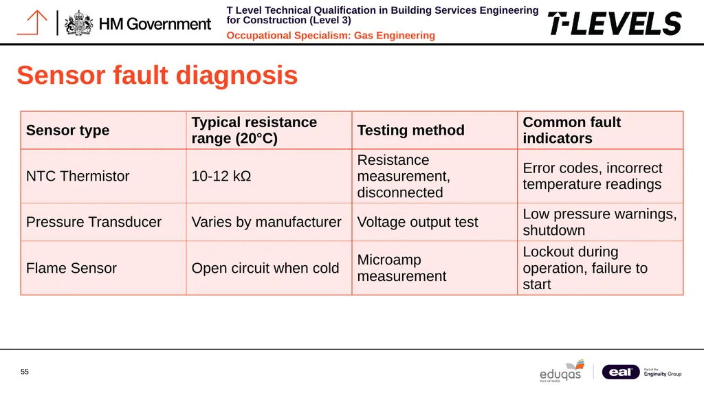
slide52. Sensor fault diagnosis Modern gas appliances use various sensors to monitor operation and ensure safety, with sensor faults being common.
Temperature sensors, often NTC thermistors, decrease resistance as temperature rises.
When testing, consider ambient temperature and let components reach room temperature before comparing resistance values.<br>
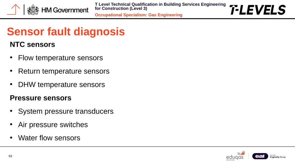
slide53. Sensor fault diagnosis NTC sensors
Flow temperature sensors
Return temperature sensors
DHW temperature sensors
Pressure sensors
System pressure transducers
Air pressure switches
Water flow sensors<br>
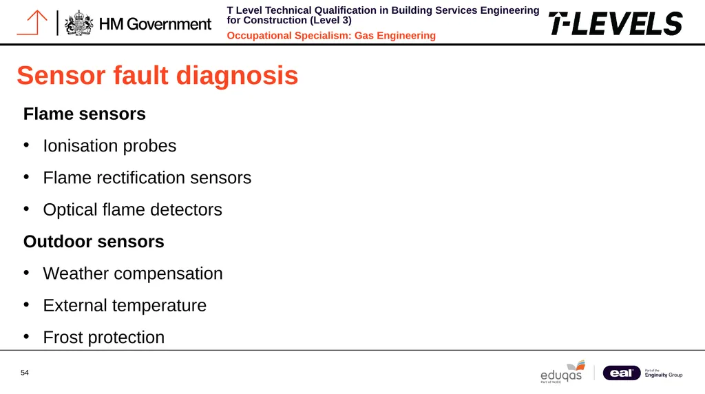
slide54. Sensor fault diagnosis Flame sensors
Ionisation probes
Flame rectification sensors
Optical flame detectors
Outdoor sensors
Weather compensation
External temperature
Frost protection<br>
slide55. Sensor fault diagnosis<br>
slide56. Using multimeters for fault-finding A reliable digital multimeter is vital for gas engineers, offering various functions for fault diagnosis.
Correct settings and accurate reading interpretation are key to avoiding errors.
Regular calibration and certification of test equipment are essential to ensure safety and accuracy.<br>
slide57. Using multimeters for fault-finding Setting up
Select appropriate function (V, Ω, A)
Choose the correct range if not auto-ranging
Zero meter if necessary
Check battery condition
Verify test lead condition<br>
slide58. Using multimeters for fault-finding Taking measurements
Ensure proper contact with test points
Observe polarity for DC measurements
Hold probes steady for accurate readings
Take multiple readings to confirm
Document all measurements<br>
slide59. Using multimeters for fault-finding Safety practices
Never test resistance on live circuits
Use insulated probes rated for voltage
Keep hands behind probe guards
Avoid contact with earthed objects
Disconnect power when changing functions<br>
slide60. Using multimeters for fault-finding Always verify your multimeter is functioning correctly before relying on its readings.
Test on a known voltage source or use the continuity function with the probes touched together before each diagnostic session.<br>
slide61. PCB diagnostics The Printed Circuit Board (PCB) controls all functions in modern gas appliances by processing sensor inputs for safe operation.
Before blaming the PCB for faults, other components should be tested.
Diagnostic LEDs on the PCB indicate appliance status and error codes as detailed by the manufacturer.<br>
slide62. PCB diagnostics PCB input testing
Verify power supply voltage
Check sensor inputs for correct values
Test switch inputs for correct signals
Inspect for damaged connections<br>
slide63. PCB diagnostics PCB output testing
Measure voltage outputs to components
Check relay operation (clicking sound)
Verify pump control signals
Test fan speed control<br>
slide64. PCB diagnostics Visual inspection
Look for burnt components
Check for water damage
Inspect fuses and fusible links
Examine for swollen capacitors<br>
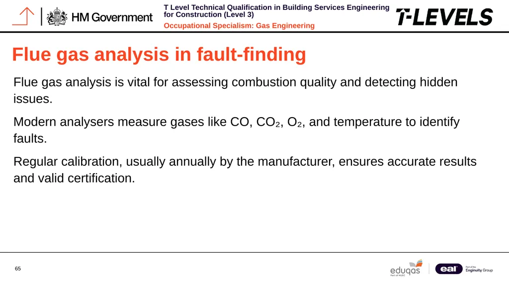
slide65. Flue gas analysis in fault-finding Flue gas analysis is vital for assessing combustion quality and detecting hidden issues.
Modern analysers measure gases like CO, CO₂, O₂, and temperature to identify faults.
Regular calibration, usually annually by the manufacturer, ensures accurate results and valid certification.<br>
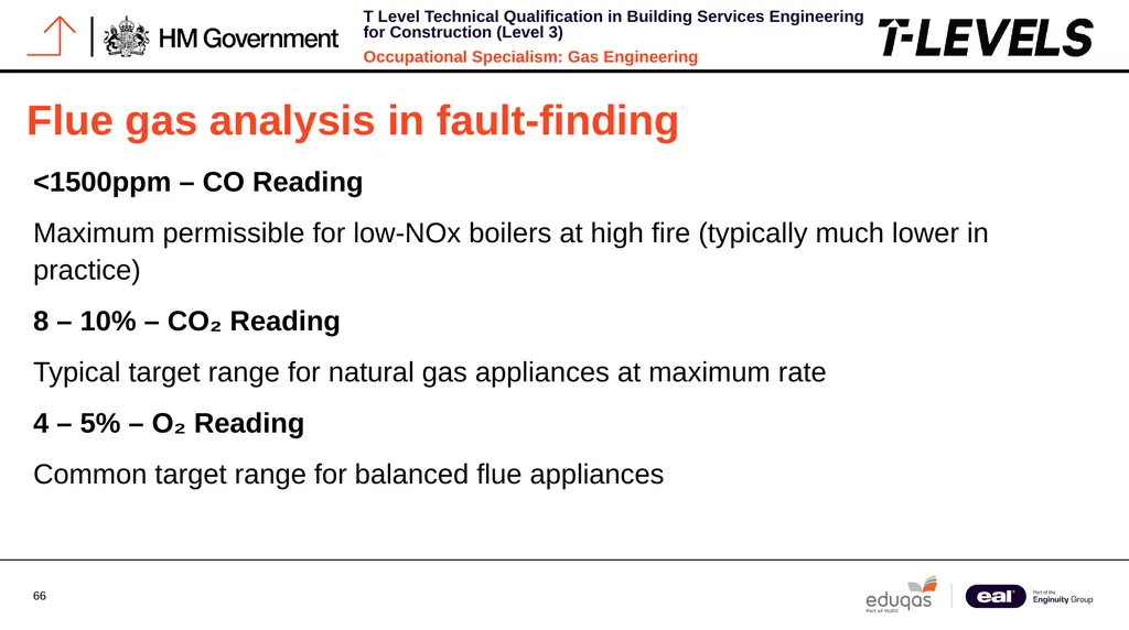
slide66. Flue gas analysis in fault-finding <1500ppm – CO Reading
Maximum permissible for low-NOx boilers at high fire (typically much lower in practice)
8 – 10% – CO₂ Reading
Typical target range for natural gas appliances at maximum rate
4 – 5% – O₂ Reading
Common target range for balanced flue appliances<br>
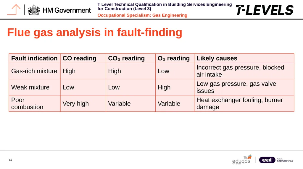
slide67. Flue gas analysis in fault-finding<br>
slide68. Diagnostic record keeping Detailed fault-finding documentation is required by Gas Safe Register rules and proves the work done.
It helps with future diagnostics, warranty claims, and shows professionalism.
Many engineers now use digital tools to record their process, including photos of tests and components.<br>
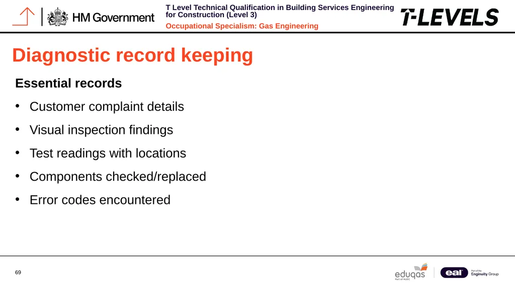
slide69. Diagnostic record keeping Essential records
Customer complaint details
Visual inspection findings
Test readings with locations
Components checked/replaced
Error codes encountered<br>
slide70. Diagnostic record keeping Documentation methods
Benchmark documentation
Service record books
Gas Safe warning notices
Digital service platforms
Photographic evidence<br>
slide71. Diagnostic record keeping Best practices
Date and time stamp all entries
Use specific terminology
Include all measurement units
Record even normal readings
Note environmental conditions<br>
slide72. Managing customer expectations Clear communication during fault-finding is key to maintaining professionalism and customer satisfaction.
Set realistic expectations, explain the process in simple terms, and be transparent about testing steps.
Keep customers informed with updates, avoid jargon, and summarise findings with repair options and preventative advice.<br>
slide73. Safety critical faults Certain faults pose immediate safety hazards and demand actions beyond normal diagnostics.
Gas engineers must recognise these and follow the Gas Industry Unsafe Situations Procedure (GIUSP).
Safety-critical faults require prompt measures like appliance disconnection and warning notices, prioritising occupant safety over convenience.
Faults are classified as Immediately Dangerous (ID) & At Risk (AR), each with specific response requirements.<br>
slide74. Emerging technologies and diagnostic implications The gas appliance industry is advancing quickly with new technologies that create unique diagnostic challenges.
Modern appliances often include connectivity for remote monitoring, requiring new fault-finding methods.
Manufacturers now provide specialised diagnostic apps and tools to access detailed data and fault histories beyond standard interfaces.<br>
slide75. Emerging technologies and diagnostic implications Smart controls
Wi-Fi connectivity issues
App integration problems
Remote sensor faults
Software update failures
Requires network diagnostics<br>
slide76. Emerging technologies and diagnostic implications Hydrogen-ready boilers
Dual fuel operation challenges
Different combustion parameters
Specialised gas valve designs
New safety systems
Modified flue requirements<br>
slide77. Emerging technologies and diagnostic implications Low-NOx systems
Complex burner designs
Pre-mix technology issues
Stricter combustion parameters
Additional sensors
More sensitive to installation factors<br>
slide78. Fault-finding toolkit essentials A well-equipped toolkit is fundamental to effective fault-finding. Professional gas engineers should maintain and regularly calibrate these essential diagnostic tools.
Many specialised tools are available for specific manufacturers’ appliances. Consider investing in these if you frequently work with particular brands, as they can significantly reduce diagnostic time.<br>
slide79. Fault-finding toolkit essentials Essential electrical tools
Digital multimeter (CAT III rated)
Clamp meter for current measurement
Non-contact voltage detector
Electrical proving unit
Insulated screwdrivers and pliers<br>
slide80. Fault-finding toolkit essentials Gas testing equipment
Digital manometer/pressure gauge
Electronic combustion analyser
Gas leak detector
CO alarm
Purge hose and adapters<br>
slide81. Fault-finding toolkit essentials Mechanical diagnostic tools
Infrared thermometer
Endoscope/borescope
Pressure testing pump
Flow measuring equipment
Magnetic pickup tools<br>
slide82. Fault-finding toolkit essentials Documentation tools
Digital camera or smartphone
Tablet with diagnostic apps
Warning notice book
Benchmark documentation
MI access (digital or printed)<br>
slide83. Summary You should now be able to:
Describe the fault-finding process and its stages.
Explain the importance of safe isolation procedures.
Identify the role of manufacturer documentation and user questioning.
Apply a structured method to select suitable diagnostic techniques.<br>
slide84. Any questions? Copyright in this document belongs to and is used under licence from the Department for Education, © 2025.
‘T-LEVELS’ and ‘T Level’ are registered trademarks of the Department for Education.
WJEC is authorised by the Department for Education to develop and deliver this T Level Technical Qualification.
WJEC operates in England under the name Eduqas which is a registered trademark of WJEC.<br>
K1.28 Fault-finding techniques, their suitability for different situations and how they are applied in practice
PowerPoint 1.28a: Introduction to fault-finding and the diagnostic process<br>
slide2. Starter A customer says their boiler keeps locking out after running hot water. There are no visible leaks or error codes. Where would you begin fault-finding?
Discuss:
What questions would you ask the user?
What would you check first — visually or with a tool?
What safety steps must come before touching anything?<br>
slide3. Objective By the end of this session, you should be able to:
Describe the fault-finding process and its stages.
Explain the importance of safe isolation procedures.
Identify the role of manufacturer documentation and user questioning.
Apply a structured method to select suitable diagnostic techniques.<br>
slide4. What is fault-finding? Fault-finding in gas engineering is a systematic method to identify appliance or system faults.
It relies on a careful approach using various techniques to pinpoint issues while prioritising safety.
Proper documentation is essential for Gas Safe Register compliance and tracking diagnostic steps.<br>
slide5. What is fault-finding? Key components
Visual inspection techniques
User feedback collection
Systematic testing procedures
Reference to manufacturer instructions (MI)
Use of appropriate test equipment<br>
slide6. What is fault-finding? Core principles
Must be carried out safely
Follow a logical sequence
Maintain clear records
Verify results through testing
Follow manufacturer guidelines<br>
slide7. The diagnostic process: step-by-step 1. Gather information
Question the user about fault symptoms
Check for error codes on display
Note visual signs of malfunction
Review service history if available<br>
slide8. The diagnostic process: step-by-step 2. Risk assess and isolate
Assess safety risks before proceeding
Perform electrical isolation
Perform gas isolation as required
Document isolation procedures<br>
slide9. The diagnostic process: step-by-step 3. Inspect visually
Look for obvious damage
Check for water leaks or staining
Inspect for burnt components
Check flue condition and integrity<br>
slide10. The diagnostic process: step-by-step 4. Carry out tests
Gas pressure testing
Electrical resistance checks
Voltage measurements
Continuity testing<br>
slide11. The diagnostic process: step-by-step 5. Interpret results
Compare readings to MI specifications
Identify out-of-range values
Determine the root cause of the fault
Document all findings<br>
slide12. The diagnostic process: step-by-step 6. Take corrective action
Replace faulty components
Clean or adjust as needed
Report unresolvable issues
Advise customer of repairs needed<br>
slide13. The diagnostic process: step-by-step 7. Verify and recommission
Retest after repairs
Recommission the appliance
Complete paperwork
Demonstrate to the customer<br>
slide14. Safe isolation procedures Before conducting any fault-finding activities, proper isolation procedures must be followed to ensure safety.
These procedures are not optional and represent a critical requirement under Gas Safe Register guidelines.<br>
slide15. Safe isolation procedures Step 1: Working environment Confirm with the designated authority that isolating the equipment or circuit is permitted and that shutting down any other electrical devices connected to the circuit is acceptable.
Step 2: Safe to touch (equipment) Choose a suitable no-contact voltage detector. Ensure the device is free from damage and test it on a proving device or a known live source. All testing instruments should be proprietary designs and comply with BS EN 61010-31, BS EN 615572, or BS EN 61243-3 standards.<br>
slide16. Safe isolation procedures Non-contact live circuit detectors (voltage sticks):
Following multiple fatalities over time, it has become standard practice in the gas industry to employ single-pole or non-contact live circuit detectors, often called voltage sticks.
These devices are used before handling appliance casings, gas, and water pipes to verify that no hazardous voltage is present as a result of a fault.<br>
slide17. Safe isolation procedures HSE Guidance Note GS38
(Electrical test equipment for use on low voltage electrical systems, fourth edition).
Specifies that no-contact live circuit detectors (voltage sticks) are intended solely for detecting live equipment and should not be relied upon to confirm that equipment is de-energised.
As a result, additional suitable tests are required to verify that the equipment is electrically dead before any work begins.<br>
slide18. Safe isolation procedures Step 3: Safe-to-touch (procedure)
Use the no-contact voltage detector to perform a sweeping scan of all exposed surfaces of the appliance casing and all exposed metal pipework, both connected to and in close proximity to the appliance/gas meter installation.
If the no-contact voltage detector indicates the presence of voltage, stop the procedure immediately and inform the customer that the installation requires the immediate attention of a suitably electrically competent person.<br>
slide19. Safe isolation procedures Step 3: Safe-to-touch (procedure)
If a fault is detected, the engineer must perform a risk assessment or consult an electrical expert to ensure safety.
If the no-contact voltage detector shows no voltage on the appliance or nearby pipework, test the device on a live 13A socket to confirm it detects 230V by sound or light.<br>
slide20. Safe isolation procedures Steps 4–8: Safe isolation
Identify the appliance's isolation point and verify that a GS 38-approved two-pole voltage indicator is working.
Confirm the appliance is functional and powered by one source.
Isolate by turning off the circuit at the SFCU, unplugging, removing the fuse, or switching off the MCB.
Apply a lock-off device and warning label, keeping the key.
Ensure all terminals are dead, and for TT earthing systems, isolate all live conductors, including neutral.<br>
slide21. Safe isolation procedures Step 9: Locking-off methods
Switch off and secure plugs, fuses, or MCBs with approved lock-off devices.
Retain keys with the worker and post warning notices to inform others.
Step 10: Verify the circuit is dead
Use a two-pole voltage indicator to confirm no voltage between earth, line, and neutral.<br>
slide22. Safe isolation procedures Step 11: Re-test the equipment
Check the voltage indicator's functionality again before proceeding.
Step 12: Safe to work on the appliance
After all checks, it is safe to work.
Continue to verify isolation when moving away and returning.<br>
slide23. Safe isolation procedures Re-energising the circuit/system
After work, inspect for damage, remove locks and labels, restore power, test appliance, and complete documentation.
Further information:
Ensure competency and compliance with any site-specific requirements or permits.
Check out Technical Bulletin 118a - Safe to touch and/or safe isolation and proving electrically dead on low-voltage single-phase supplies (below 1000 volts)<br>
slide24. Safe isolation procedures Gas isolation
Close the Emergency Control Valve (ECV) or appliance isolation valve
Verify zero pressure at the test nipple using the appropriate gauge
Purge residual gas safely if required
Record isolation status in the workbook or digital log
Apply a warning label if the system is left isolated
Inform the customer of isolation and reasons<br>
slide25. Safe isolation procedures Never attempt fault-finding on live electrical circuits or pressurised gas systems.
Failure to properly isolate before work is a breach of safety regulations and may result in serious injury or death.<br>
slide26. Questioning the customer Asking effective questions is an essential diagnostic technique that can save considerable time and help identify problem areas before any physical examination starts.
Customers' answers often provide important hints about intermittent problems that might not appear during your visit.
Make sure to document customer responses in your workbook since they serve as part of your diagnostic record and could be necessary for warranty claims or compliance purposes.
Avoid leading questions that may prompt customers to give answers they believe you want instead of truthful information.<br>
slide27. Questioning the customer Event details
What was happening when the fault first occurred?
Was there anything unusual (sounds, smells, etc.)?
What time of day does it typically happen?
Fault pattern
Is the problem constant or intermittent?
Does it happen after specific actions?
How long has this been occurring?<br>
slide28. Questioning the customer History and changes
Have they had similar issues before?
Any recent changes to property or usage?
Has anyone else worked on the appliance?<br>
slide29. Reading manufacturer fault charts Manufacturer Instructions (MIs) include detailed fault-finding charts designed to offer structured methods for diagnosing particular appliance problems.
These charts are mandatory references to consult during any fault-finding process.
Usually formatted as flowcharts, manufacturer fault charts lead you through a logical series of tests depending on the symptoms observed.
They often specify expected component test values unique to the appliance model.<br>
slide30. Reading manufacturer fault charts Many modern appliances now incorporate QR codes that connect to online versions of fault charts, which are often more current than the printed manuals provided with the appliance.<br>
slide31. Reading manufacturer fault charts Key components of fault charts
Error codes and their meanings
Diagnostic LED patterns
Expected sensor resistance values
Voltage test points
Component location diagrams
Step-by-step testing procedures<br>
slide32. Reading manufacturer fault charts Using fault charts correctly
Follow the sequence exactly as shown
Never skip steps or make assumptions
Document all readings taken
Use specified test equipment only
Compare results with specified ranges
Never bypass the manufacturer's recommended fault-finding sequence. Doing so may lead to misdiagnosis, unnecessary parts replacement, or creation of dangerous conditions.<br>
slide33. Case study: Intermittent hot water fault The user says: 'My water runs cold after a few seconds.' The boiler is on, no fault code is showing.
Information gathering
How long has this been happening?
Does it affect all taps or just some?
Has water pressure changed recently?
Any other appliances affected?
Recent work done on plumbing?<br>
slide34. Case study: Intermittent hot water fault Potential causes
Plate heat exchanger blockage (limescale)
Domestic hot water (DHW) sensor fault
Diverter valve is sticking or damaged
Flow switch malfunction
Pump speed/operation issues
PCB fault affecting DHW demand detection<br>
slide35. Case study: Intermittent hot water fault Diagnostic plan
Check inlet water pressure
Test DHW sensor resistance values
Inspect diverter valve operation
Monitor flow switch activation
Check for error history in PCB memory
Test pump operation and speed settings<br>
slide36. Case study: Intermittent hot water fault Let's discuss as a group:
What additional diagnostic steps might you take?
How would you prioritise these checks?
What safety precautions are specific to this scenario?<br>
slide37. The importance of pressure testing Pressure testing is fundamental to gas appliance fault-finding.
Incorrect gas pressure is a common cause of operational issues and can lead to dangerous conditions if not properly checked and rectified.
Working pressure, standing pressure and burner pressure all provide valuable diagnostic information.
Each measurement has specific test points and expected values that must be checked against manufacturer specifications.<br>
slide38. The importance of pressure testing Modern pressure gauges often feature digital displays with data logging capabilities, allowing for more precise readings and the ability to monitor pressure fluctuations over time.
These tools are invaluable for diagnosing intermittent pressure-related faults.<br>
slide39. The importance of pressure testing Standing pressure
Measured with appliance off
Indicates supply pressure to the property
Typically 21 mbar for natural gas
Low reading suggests supply issues<br>
slide40. The importance of pressure testing Working pressure
Measured with appliance running
Should not drop more than 1 mbar from standing
Significant drop indicates pipework restrictions
Must be documented on benchmark<br>
slide41. Quick knowledge check Which step comes first in the fault-finding process?
Test the electrodes
Check the MI fault chart
Ask the customer questions
Turn the appliance back on<br>
slide42. Quick knowledge check Correct answer: C) Ask the customer questions
The fault-finding process should always begin with gathering information.
Customer questioning provides valuable context about the fault before any technical investigation begins.
This initial step helps focus your diagnostic efforts and can save significant time by identifying patterns or potential external factors affecting the appliance.<br>
slide43. Electrical testing fundamentals Electrical fault-finding is essential for diagnosing modern gas appliances, which rely heavily on electronic controls and sensors.
Understanding how to properly use electrical testing equipment is a core competency for gas engineers.
When testing electrical components, always refer to manufacturer documentation for the specific resistance, voltage, or continuity values expected.
These can vary significantly between appliance models and manufacturers.<br>
slide44. Electrical testing fundamentals Recording your electrical test results provides documentation of the fault-finding process and may be required for warranty claims or compliance with Gas Safe Register requirements.<br>
slide45. Electrical testing fundamentals Continuity testing
Used to check for breaks in circuits
Tests fuses, wiring, and connections
Set meter to continuity/resistance mode
Zero reading indicates good continuity<br>
slide46. Electrical testing fundamentals Resistance testing
Checks sensors and thermistors
Set meter to ohms (Ω) scale
Compare to MI specifications
NTC sensors decrease resistance when hot<br>
slide47. Electrical testing fundamentals Voltage testing
Confirms power to components
Set meter to AC/DC voltage as appropriate
Always test with circuit powered
Compare to expected values in MI
Always ensure electrical isolation before connecting test leads to components for resistance or continuity testing. Voltage testing must be performed with extreme caution on live circuits.<br>
slide48. Common fault patterns in combination boilers Combination boilers exhibit certain fault patterns that experienced engineers learn to recognise.
Understanding these common fault signatures can significantly speed up the diagnostic process.
While these patterns provide useful starting points, always follow the manufacturer's diagnostic procedures rather than relying solely on past experience.
Similar symptoms can have different causes in different appliance models.<br>
slide49. Common fault patterns in combination boilers Intermittent lockouts
Flame detection issues
Electrode gaps incorrect
Condensate blockage
Fan speed fluctuations
Gas valve operation issues<br>
slide50. Common fault patterns in combination boilers No hot water
Diverter valve failure
DHW flow switch issues
Plate heat exchanger blockage
DHW sensor failure
PCB communication problems<br>
slide51. Common fault patterns in combination boilers No central heating
Pump failure or blockage
System pressure loss
CH sensor fault
PCB relay failure
Programmer/timer issues<br>
slide52. Sensor fault diagnosis Modern gas appliances use various sensors to monitor operation and ensure safety, with sensor faults being common.
Temperature sensors, often NTC thermistors, decrease resistance as temperature rises.
When testing, consider ambient temperature and let components reach room temperature before comparing resistance values.<br>
slide53. Sensor fault diagnosis NTC sensors
Flow temperature sensors
Return temperature sensors
DHW temperature sensors
Pressure sensors
System pressure transducers
Air pressure switches
Water flow sensors<br>
slide54. Sensor fault diagnosis Flame sensors
Ionisation probes
Flame rectification sensors
Optical flame detectors
Outdoor sensors
Weather compensation
External temperature
Frost protection<br>
slide55. Sensor fault diagnosis<br>
slide56. Using multimeters for fault-finding A reliable digital multimeter is vital for gas engineers, offering various functions for fault diagnosis.
Correct settings and accurate reading interpretation are key to avoiding errors.
Regular calibration and certification of test equipment are essential to ensure safety and accuracy.<br>
slide57. Using multimeters for fault-finding Setting up
Select appropriate function (V, Ω, A)
Choose the correct range if not auto-ranging
Zero meter if necessary
Check battery condition
Verify test lead condition<br>
slide58. Using multimeters for fault-finding Taking measurements
Ensure proper contact with test points
Observe polarity for DC measurements
Hold probes steady for accurate readings
Take multiple readings to confirm
Document all measurements<br>
slide59. Using multimeters for fault-finding Safety practices
Never test resistance on live circuits
Use insulated probes rated for voltage
Keep hands behind probe guards
Avoid contact with earthed objects
Disconnect power when changing functions<br>
slide60. Using multimeters for fault-finding Always verify your multimeter is functioning correctly before relying on its readings.
Test on a known voltage source or use the continuity function with the probes touched together before each diagnostic session.<br>
slide61. PCB diagnostics The Printed Circuit Board (PCB) controls all functions in modern gas appliances by processing sensor inputs for safe operation.
Before blaming the PCB for faults, other components should be tested.
Diagnostic LEDs on the PCB indicate appliance status and error codes as detailed by the manufacturer.<br>
slide62. PCB diagnostics PCB input testing
Verify power supply voltage
Check sensor inputs for correct values
Test switch inputs for correct signals
Inspect for damaged connections<br>
slide63. PCB diagnostics PCB output testing
Measure voltage outputs to components
Check relay operation (clicking sound)
Verify pump control signals
Test fan speed control<br>
slide64. PCB diagnostics Visual inspection
Look for burnt components
Check for water damage
Inspect fuses and fusible links
Examine for swollen capacitors<br>
slide65. Flue gas analysis in fault-finding Flue gas analysis is vital for assessing combustion quality and detecting hidden issues.
Modern analysers measure gases like CO, CO₂, O₂, and temperature to identify faults.
Regular calibration, usually annually by the manufacturer, ensures accurate results and valid certification.<br>
slide66. Flue gas analysis in fault-finding <1500ppm – CO Reading
Maximum permissible for low-NOx boilers at high fire (typically much lower in practice)
8 – 10% – CO₂ Reading
Typical target range for natural gas appliances at maximum rate
4 – 5% – O₂ Reading
Common target range for balanced flue appliances<br>
slide67. Flue gas analysis in fault-finding<br>
slide68. Diagnostic record keeping Detailed fault-finding documentation is required by Gas Safe Register rules and proves the work done.
It helps with future diagnostics, warranty claims, and shows professionalism.
Many engineers now use digital tools to record their process, including photos of tests and components.<br>
slide69. Diagnostic record keeping Essential records
Customer complaint details
Visual inspection findings
Test readings with locations
Components checked/replaced
Error codes encountered<br>
slide70. Diagnostic record keeping Documentation methods
Benchmark documentation
Service record books
Gas Safe warning notices
Digital service platforms
Photographic evidence<br>
slide71. Diagnostic record keeping Best practices
Date and time stamp all entries
Use specific terminology
Include all measurement units
Record even normal readings
Note environmental conditions<br>
slide72. Managing customer expectations Clear communication during fault-finding is key to maintaining professionalism and customer satisfaction.
Set realistic expectations, explain the process in simple terms, and be transparent about testing steps.
Keep customers informed with updates, avoid jargon, and summarise findings with repair options and preventative advice.<br>
slide73. Safety critical faults Certain faults pose immediate safety hazards and demand actions beyond normal diagnostics.
Gas engineers must recognise these and follow the Gas Industry Unsafe Situations Procedure (GIUSP).
Safety-critical faults require prompt measures like appliance disconnection and warning notices, prioritising occupant safety over convenience.
Faults are classified as Immediately Dangerous (ID) & At Risk (AR), each with specific response requirements.<br>
slide74. Emerging technologies and diagnostic implications The gas appliance industry is advancing quickly with new technologies that create unique diagnostic challenges.
Modern appliances often include connectivity for remote monitoring, requiring new fault-finding methods.
Manufacturers now provide specialised diagnostic apps and tools to access detailed data and fault histories beyond standard interfaces.<br>
slide75. Emerging technologies and diagnostic implications Smart controls
Wi-Fi connectivity issues
App integration problems
Remote sensor faults
Software update failures
Requires network diagnostics<br>
slide76. Emerging technologies and diagnostic implications Hydrogen-ready boilers
Dual fuel operation challenges
Different combustion parameters
Specialised gas valve designs
New safety systems
Modified flue requirements<br>
slide77. Emerging technologies and diagnostic implications Low-NOx systems
Complex burner designs
Pre-mix technology issues
Stricter combustion parameters
Additional sensors
More sensitive to installation factors<br>
slide78. Fault-finding toolkit essentials A well-equipped toolkit is fundamental to effective fault-finding. Professional gas engineers should maintain and regularly calibrate these essential diagnostic tools.
Many specialised tools are available for specific manufacturers’ appliances. Consider investing in these if you frequently work with particular brands, as they can significantly reduce diagnostic time.<br>
slide79. Fault-finding toolkit essentials Essential electrical tools
Digital multimeter (CAT III rated)
Clamp meter for current measurement
Non-contact voltage detector
Electrical proving unit
Insulated screwdrivers and pliers<br>
slide80. Fault-finding toolkit essentials Gas testing equipment
Digital manometer/pressure gauge
Electronic combustion analyser
Gas leak detector
CO alarm
Purge hose and adapters<br>
slide81. Fault-finding toolkit essentials Mechanical diagnostic tools
Infrared thermometer
Endoscope/borescope
Pressure testing pump
Flow measuring equipment
Magnetic pickup tools<br>
slide82. Fault-finding toolkit essentials Documentation tools
Digital camera or smartphone
Tablet with diagnostic apps
Warning notice book
Benchmark documentation
MI access (digital or printed)<br>
slide83. Summary You should now be able to:
Describe the fault-finding process and its stages.
Explain the importance of safe isolation procedures.
Identify the role of manufacturer documentation and user questioning.
Apply a structured method to select suitable diagnostic techniques.<br>
slide84. Any questions? Copyright in this document belongs to and is used under licence from the Department for Education, © 2025.
‘T-LEVELS’ and ‘T Level’ are registered trademarks of the Department for Education.
WJEC is authorised by the Department for Education to develop and deliver this T Level Technical Qualification.
WJEC operates in England under the name Eduqas which is a registered trademark of WJEC.<br>