
Post Seismic Bridge Inspection Abutment Approach

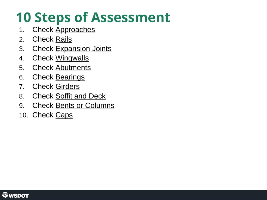
Description: Post Seismic Bridge Inspection Abutment Approach 10 Steps of Assessment Check Approaches Check Rails Check Expansion Joints Check Wingwalls Check Abutments Check Bearings Check Girders Check Soffit and Deck Check Bents or Columns Check Caps
Related Topics
Download Presentation
"Post Seismic Bridge Inspection Abutment Approach" is the property of its rightful owner. Permission is granted to download and print the materials on this website for personal, non-commercial use only, and to display it on your personal computer provided you do not modify the materials and that you retain all copyright notices contained in the materials. By downloading content from our website, you accept the terms of this agreement.
Presentation Transcript
slide1. Post Seismic Bridge Inspection Abutment Approach<br>
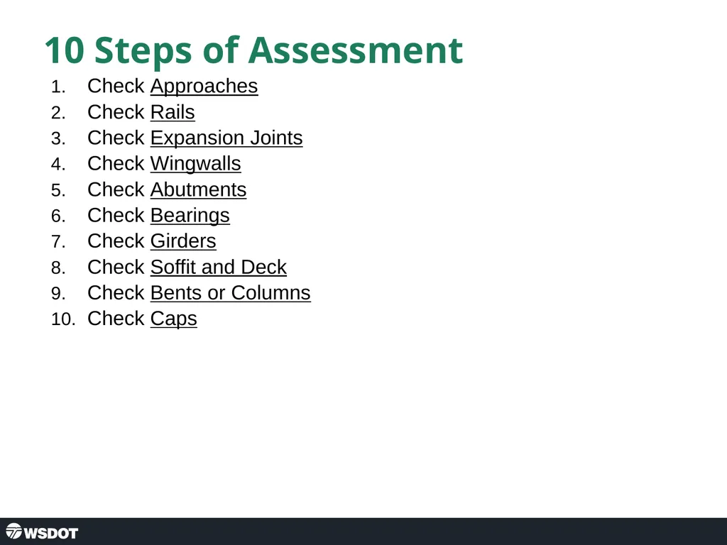
slide2. 10 Steps of Assessment Check Approaches
Check Rails
Check Expansion Joints
Check Wingwalls
Check Abutments
Check Bearings
Check Girders
Check Soffit and Deck
Check Bents or Columns
Check Caps<br>
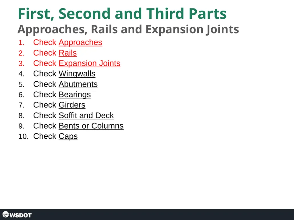
slide3. First, Second and Third Parts Approaches, Rails and Expansion Joints Check Approaches
Check Rails
Check Expansion Joints
Check Wingwalls
Check Abutments
Check Bearings
Check Girders
Check Soffit and Deck
Check Bents or Columns
Check Caps<br>
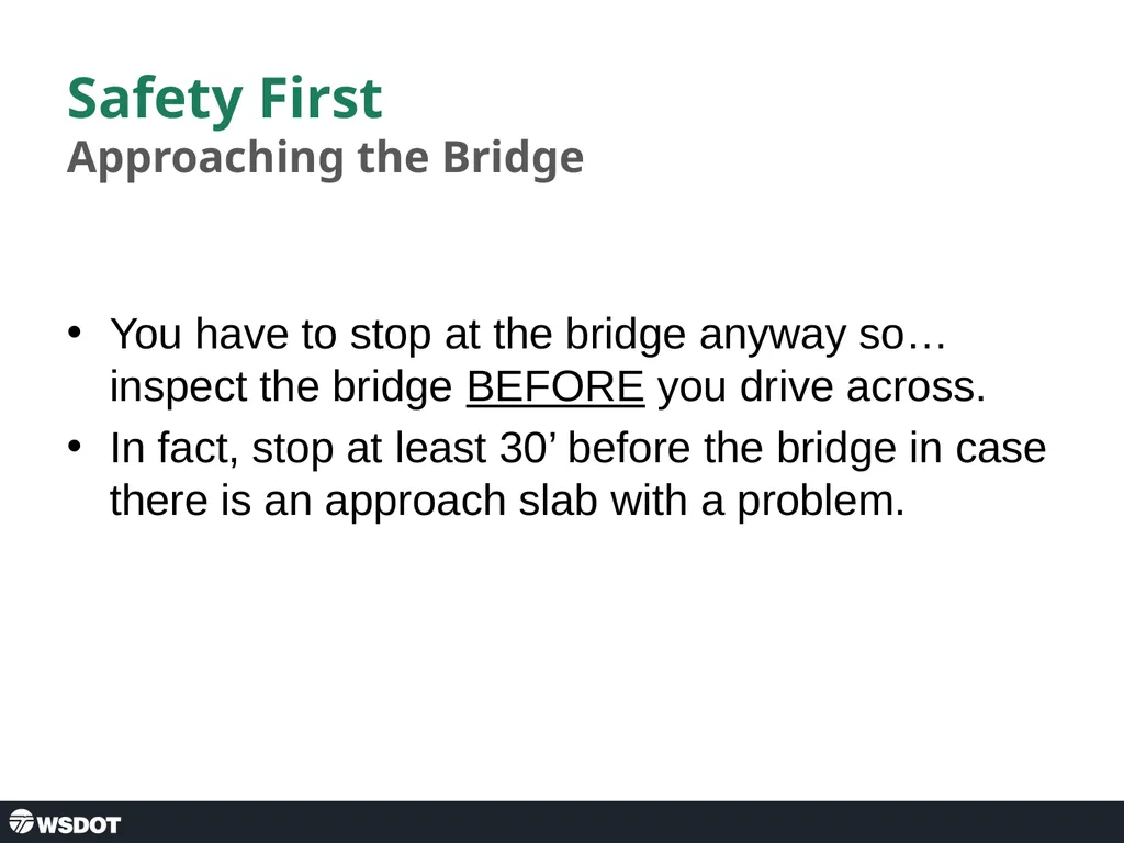
slide4. Safety First Approaching the Bridge You have to stop at the bridge anyway so… inspect the bridge BEFORE you drive across.
In fact, stop at least 30’ before the bridge in case there is an approach slab with a problem.<br>
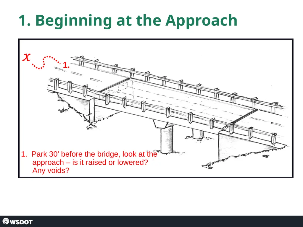
slide5. 1. Beginning at the Approach 1. X 1. Park 30’ before the bridge, look at the approach – is it raised or lowered? Any voids?<br>
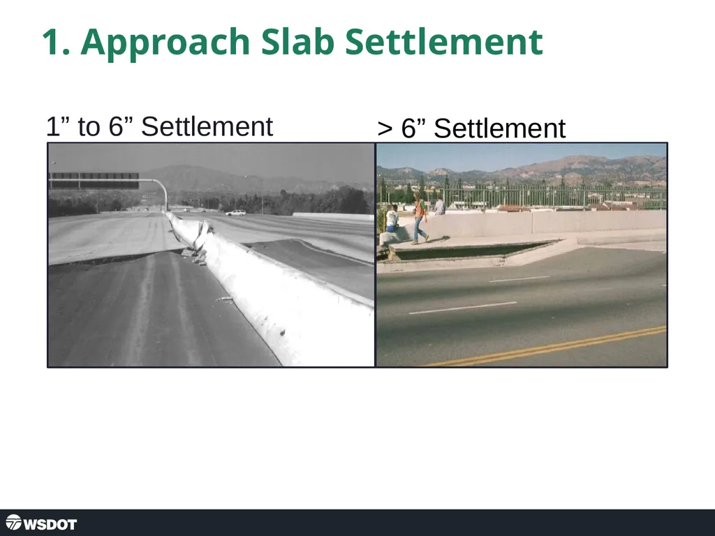
slide6. 1. Approach Slab Settlement 1” to 6” Settlement > 6” Settlement<br>
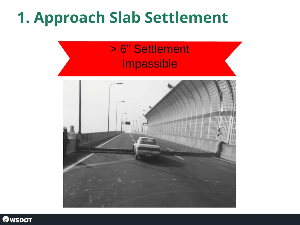
slide7. 1. Approach Slab Settlement > 6” Settlement
Impassible<br>
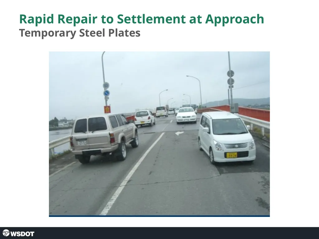
slide8. Rapid Repair to Settlement at Approach Temporary Steel Plates<br>
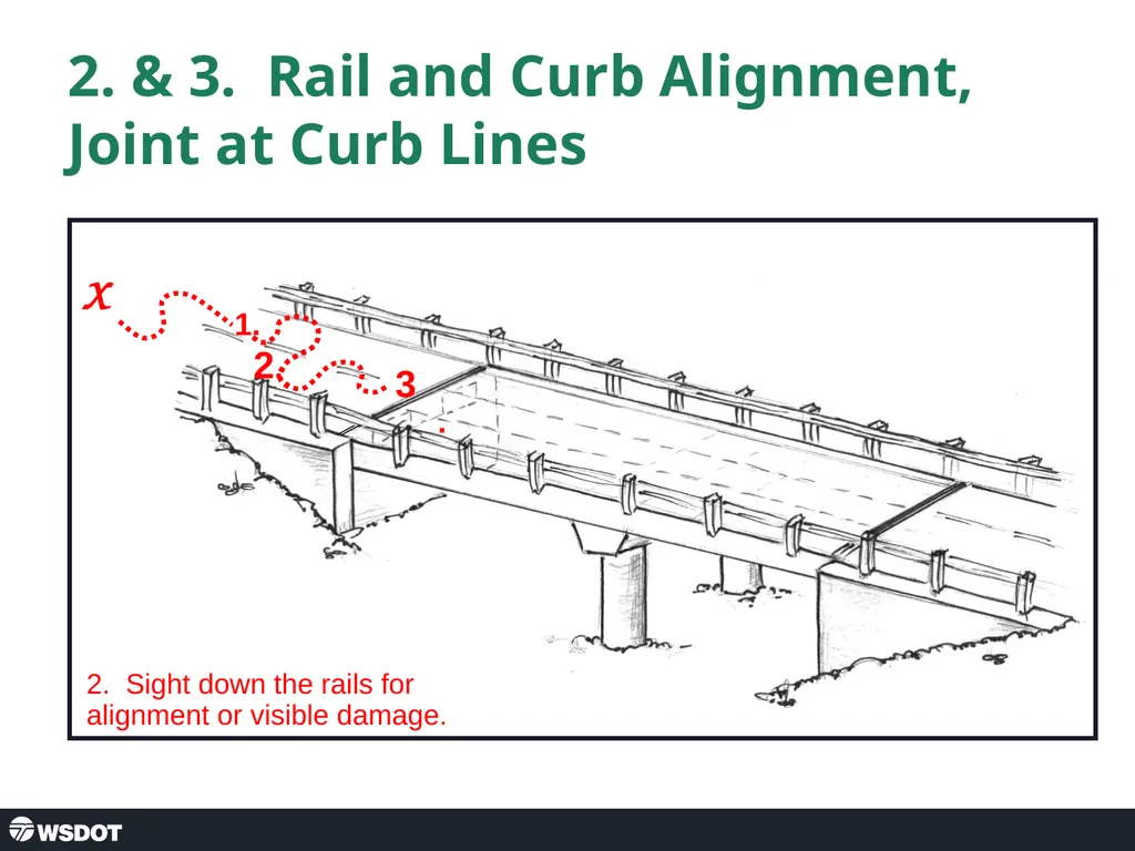
slide9. 2. & 3. Rail and Curb Alignment, Joint at Curb Lines 1. X 2. Sight down the rails for alignment or visible damage. 2. 3.<br>
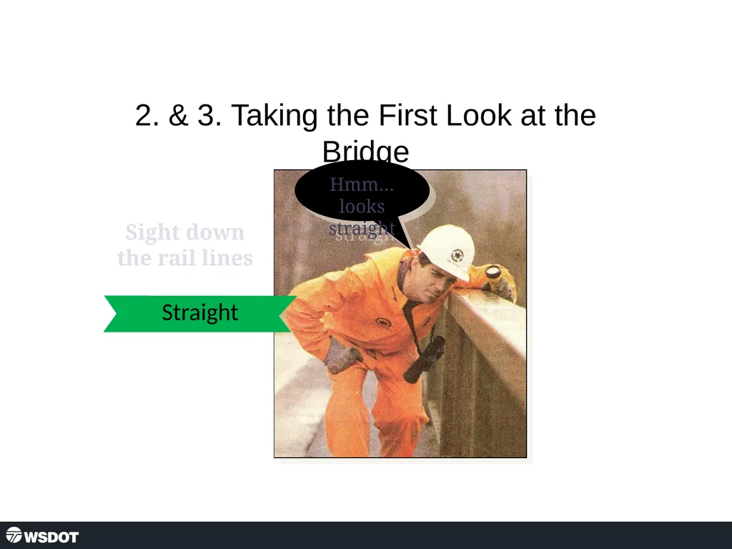
slide10. 2. & 3. Taking the First Look at the Bridge Sight down the rail lines Straight<br>
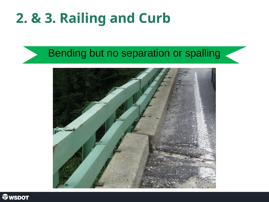
slide11. 2. & 3. Railing and Curb Bending but no separation or spalling<br>
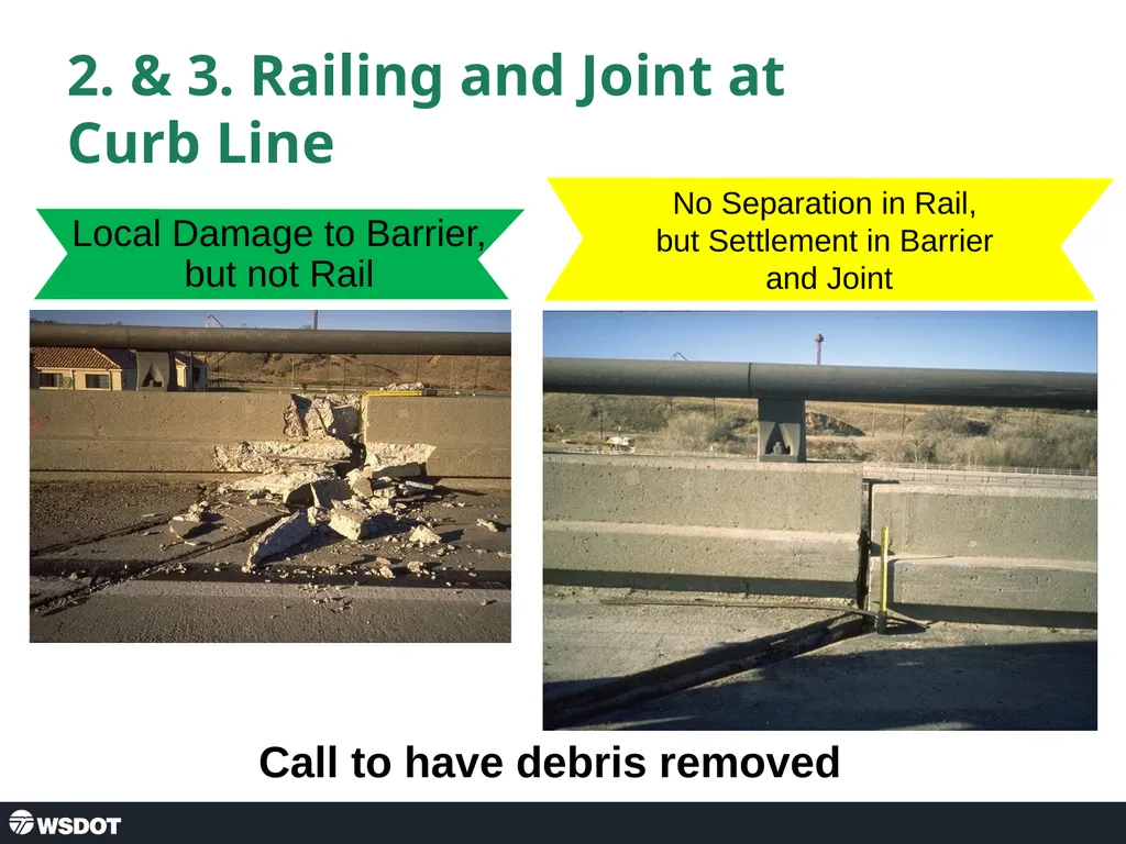
slide12. 2. & 3. Railing and Joint at Curb Line Call to have debris removed Local Damage to Barrier, but not Rail No Separation in Rail,
but Settlement in Barrier
and Joint<br>
slide13. 10 Steps of Assessment Check Approaches
Check Rails
Check Expansion Joints
Check Wingwalls
Check Abutments
Check Bearings
Check Girders
Check Soffit and Deck
Check Bents or Columns
Check Caps<br>
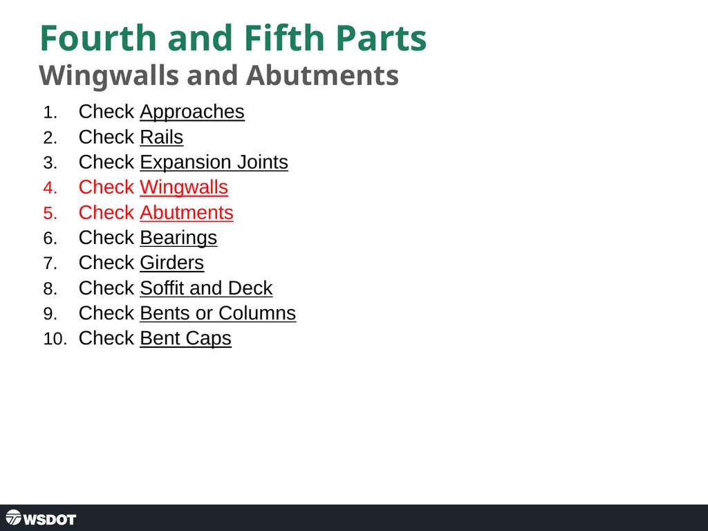
slide14. Fourth and Fifth Parts Wingwalls and Abutments Check Approaches
Check Rails
Check Expansion Joints
Check Wingwalls
Check Abutments
Check Bearings
Check Girders
Check Soffit and Deck
Check Bents or Columns
Check Bent Caps<br>
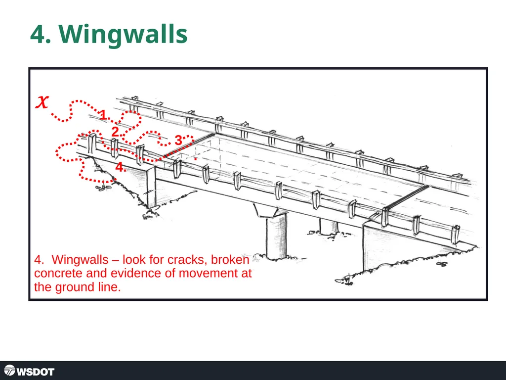
slide15. 4. Wingwalls 1. X 4. Wingwalls – look for cracks, broken concrete and evidence of movement at the ground line. 2. 3. 4.<br>
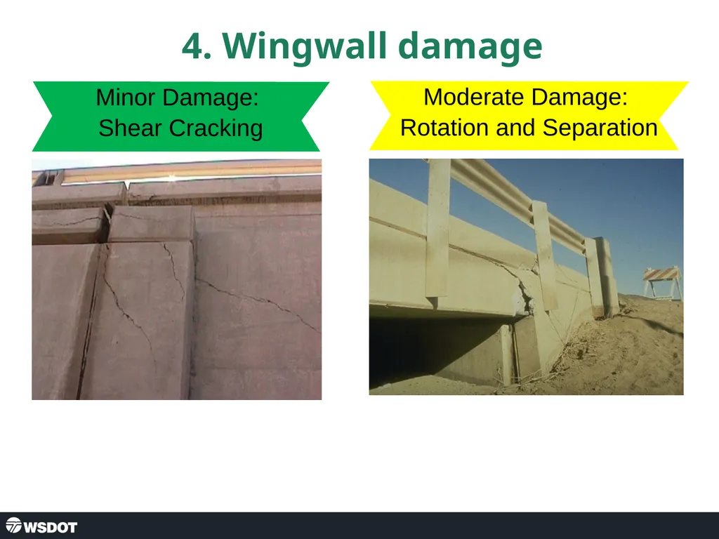
slide16. 4. Wingwall damage Minor Damage:
Shear Cracking Moderate Damage:
Rotation and Separation<br>
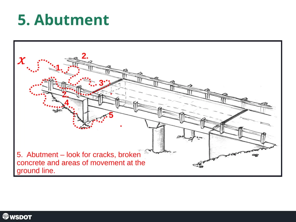
slide17. 5. Abutment 1. X 5. Abutment – look for cracks, broken concrete and areas of movement at the ground line. 2. 2. 3. 4. 5. Abutments
Transverse movement may displace or crack the cheek-walls, wing-walls (Figures 5-45, 5-46) and any abutment shear blocks. Longitudinal movement during an earthquake may damage the abutment stem and/or backwall (Figure 5-47). Examine abutment backwall and wing-walls for flexural or shear cracks, which may be less obvious than abutment movement. Loose or settled fill, slope failures, liquefaction, fissures and differential settlements at the base of the abutments may be observed as evidence of foundation movement and possible damage. If any evidence of cracking or displacement is observed, be sure to note it on the form and specify the location in the ‘Comments’ field.<br>
slide18. 5. Abutment Damages Figure 5-47. Moderate Damage: Spalling and Cracking of Abutment, Movement at Ground Level (MO) Note that the rebar is not rusting, an indication that damage is recent. Abutments
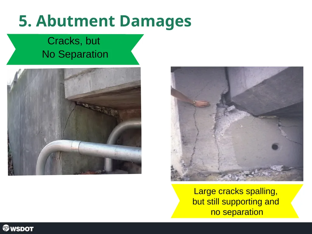
Transverse movement may displace or crack the cheek-walls, wing-walls (Figures 5-45, 5-46) and any abutment shear blocks. Longitudinal movement during an earthquake may damage the abutment stem and/or backwall (Figure 5-47). Examine abutment backwall and wing-walls for flexural or shear cracks, which may be less obvious than abutment movement. Loose or settled fill, slope failures, liquefaction, fissures and differential settlements at the base of the abutments may be observed as evidence of foundation movement and possible damage. If any evidence of cracking or displacement is observed, be sure to note it on the form and specify the location in the ‘Comments’ field. Cracks, but
No Separation Large cracks spalling,
but still supporting and
no separation<br>
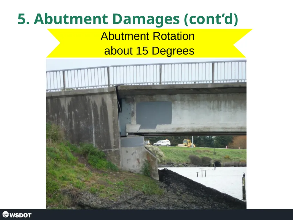
slide19. 5. Abutment Damages (cont’d) Abutment Rotation
about 15 Degrees<br>
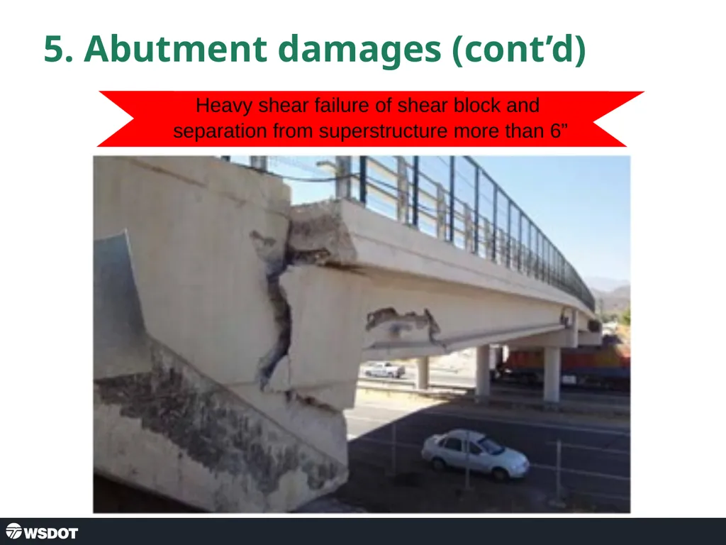
slide20. 5. Abutment damages (cont’d) Heavy shear failure of shear block and
separation from superstructure more than 6”<br>
slide21. Exercise Fill out assessment forms for the last bridge.<br>
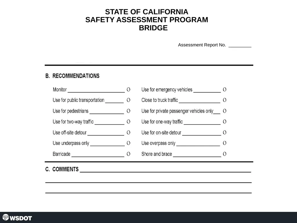
slide22. STATE OF CALIFORNIA
SAFETY ASSESSMENT PROGRAM
BRIDGE
Assessment Report No. _________<br>
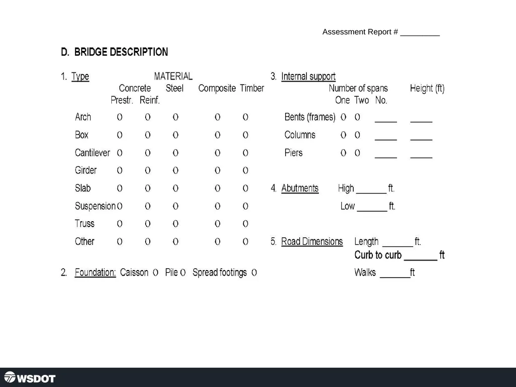
slide23. Assessment Report # _________<br>
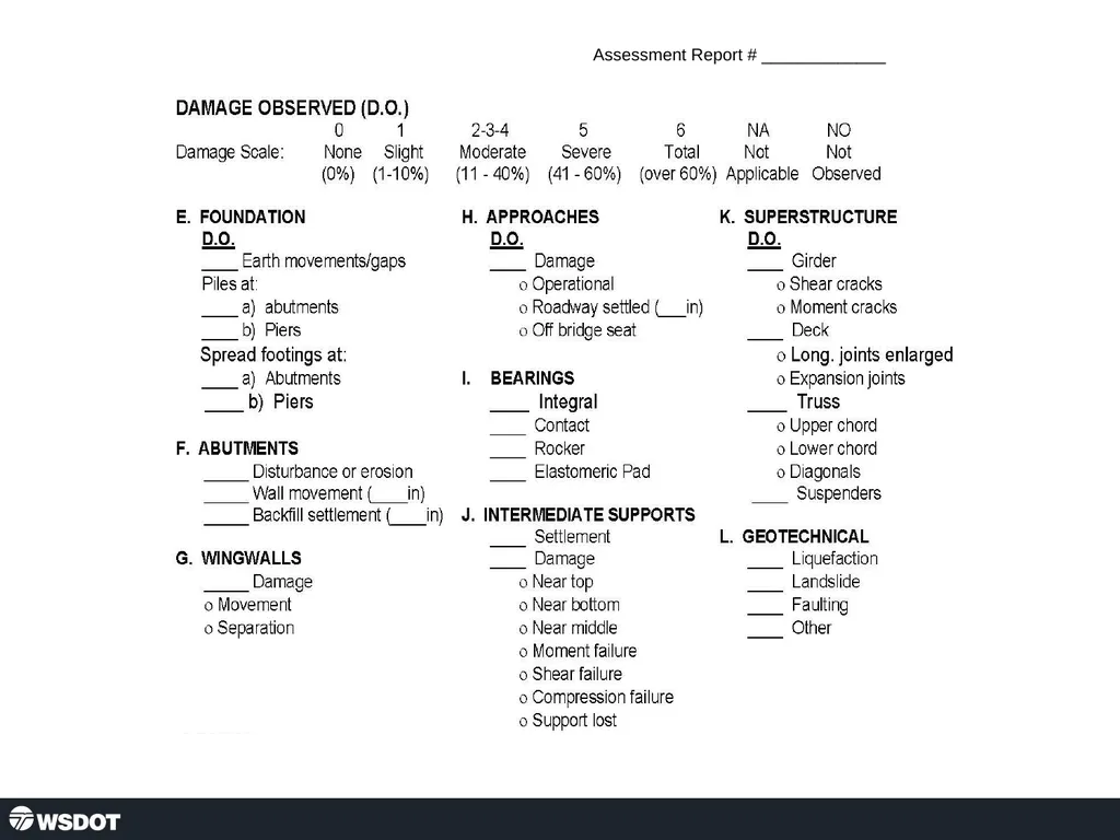
slide24. Assessment Report # _____________<br>
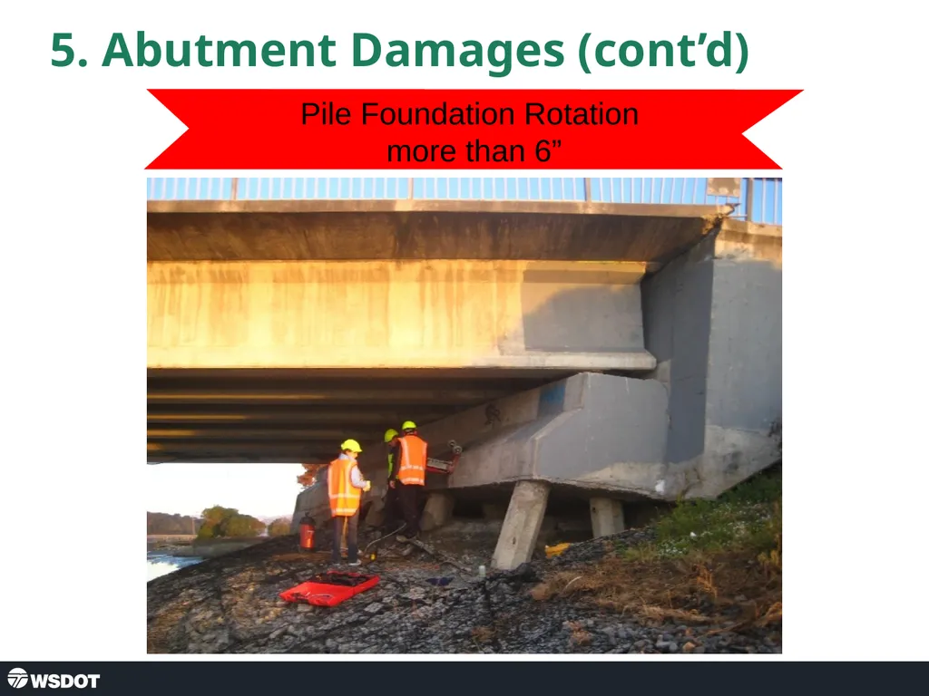
slide25. 5. Abutment Damages (cont’d) Pile Foundation Rotation
more than 6”<br>
slide2. 10 Steps of Assessment Check Approaches
Check Rails
Check Expansion Joints
Check Wingwalls
Check Abutments
Check Bearings
Check Girders
Check Soffit and Deck
Check Bents or Columns
Check Caps<br>
slide3. First, Second and Third Parts Approaches, Rails and Expansion Joints Check Approaches
Check Rails
Check Expansion Joints
Check Wingwalls
Check Abutments
Check Bearings
Check Girders
Check Soffit and Deck
Check Bents or Columns
Check Caps<br>
slide4. Safety First Approaching the Bridge You have to stop at the bridge anyway so… inspect the bridge BEFORE you drive across.
In fact, stop at least 30’ before the bridge in case there is an approach slab with a problem.<br>
slide5. 1. Beginning at the Approach 1. X 1. Park 30’ before the bridge, look at the approach – is it raised or lowered? Any voids?<br>
slide6. 1. Approach Slab Settlement 1” to 6” Settlement > 6” Settlement<br>
slide7. 1. Approach Slab Settlement > 6” Settlement
Impassible<br>
slide8. Rapid Repair to Settlement at Approach Temporary Steel Plates<br>
slide9. 2. & 3. Rail and Curb Alignment, Joint at Curb Lines 1. X 2. Sight down the rails for alignment or visible damage. 2. 3.<br>
slide10. 2. & 3. Taking the First Look at the Bridge Sight down the rail lines Straight<br>
slide11. 2. & 3. Railing and Curb Bending but no separation or spalling<br>
slide12. 2. & 3. Railing and Joint at Curb Line Call to have debris removed Local Damage to Barrier, but not Rail No Separation in Rail,
but Settlement in Barrier
and Joint<br>
slide13. 10 Steps of Assessment Check Approaches
Check Rails
Check Expansion Joints
Check Wingwalls
Check Abutments
Check Bearings
Check Girders
Check Soffit and Deck
Check Bents or Columns
Check Caps<br>
slide14. Fourth and Fifth Parts Wingwalls and Abutments Check Approaches
Check Rails
Check Expansion Joints
Check Wingwalls
Check Abutments
Check Bearings
Check Girders
Check Soffit and Deck
Check Bents or Columns
Check Bent Caps<br>
slide15. 4. Wingwalls 1. X 4. Wingwalls – look for cracks, broken concrete and evidence of movement at the ground line. 2. 3. 4.<br>
slide16. 4. Wingwall damage Minor Damage:
Shear Cracking Moderate Damage:
Rotation and Separation<br>
slide17. 5. Abutment 1. X 5. Abutment – look for cracks, broken concrete and areas of movement at the ground line. 2. 2. 3. 4. 5. Abutments
Transverse movement may displace or crack the cheek-walls, wing-walls (Figures 5-45, 5-46) and any abutment shear blocks. Longitudinal movement during an earthquake may damage the abutment stem and/or backwall (Figure 5-47). Examine abutment backwall and wing-walls for flexural or shear cracks, which may be less obvious than abutment movement. Loose or settled fill, slope failures, liquefaction, fissures and differential settlements at the base of the abutments may be observed as evidence of foundation movement and possible damage. If any evidence of cracking or displacement is observed, be sure to note it on the form and specify the location in the ‘Comments’ field.<br>
slide18. 5. Abutment Damages Figure 5-47. Moderate Damage: Spalling and Cracking of Abutment, Movement at Ground Level (MO) Note that the rebar is not rusting, an indication that damage is recent. Abutments
Transverse movement may displace or crack the cheek-walls, wing-walls (Figures 5-45, 5-46) and any abutment shear blocks. Longitudinal movement during an earthquake may damage the abutment stem and/or backwall (Figure 5-47). Examine abutment backwall and wing-walls for flexural or shear cracks, which may be less obvious than abutment movement. Loose or settled fill, slope failures, liquefaction, fissures and differential settlements at the base of the abutments may be observed as evidence of foundation movement and possible damage. If any evidence of cracking or displacement is observed, be sure to note it on the form and specify the location in the ‘Comments’ field. Cracks, but
No Separation Large cracks spalling,
but still supporting and
no separation<br>
slide19. 5. Abutment Damages (cont’d) Abutment Rotation
about 15 Degrees<br>
slide20. 5. Abutment damages (cont’d) Heavy shear failure of shear block and
separation from superstructure more than 6”<br>
slide21. Exercise Fill out assessment forms for the last bridge.<br>
slide22. STATE OF CALIFORNIA
SAFETY ASSESSMENT PROGRAM
BRIDGE
Assessment Report No. _________<br>
slide23. Assessment Report # _________<br>
slide24. Assessment Report # _____________<br>
slide25. 5. Abutment Damages (cont’d) Pile Foundation Rotation
more than 6”<br>