
Progress in CIGRE Working Groups on Lightning and
SN
Published · 45 slides · 0 views
1 / 1
Description
Progress in CIGRE Working Groups on Lightning and Grounding (and IEEE Task Force on HVDC Line Design) Member Report: William A. Chisholm W.A.Chisholmieee.org 19 July 2016 Meetings Attended Montreal, May 2016 B2.56, Ground Potential Rise at
Related Topics
Share
Embed code
Download this presentation From Below
"Progress in CIGRE Working Groups on Lightning and" is the property of its rightful owner. Permission is granted to download and print the materials on this website for personal, non-commercial use only, and to display it on your personal computer provided you do not modify the materials and that you retain all copyright notices contained in the materials. By downloading content from our website, you accept the terms of this agreement.
Presentation Transcript
01
Progress in CIGRE Working Groups on Lightning and Grounding
(and IEEE Task Force on HVDC Line Design) Member Report: William A. Chisholm
W.A.Chisholm@ieee.org
19 July 2016<br>
W.A.Chisholm@ieee.org
19 July 2016<br>
02
Meetings Attended Montreal, May 2016
B2.56, Ground Potential Rise at Overhead AC Transmission Line Structures during Power Frequency Faults
B2.AG06.TF007, Don’t Put your Arresters near our Dampers
Petrache paper on CEATI studies (CDEGS HiFreq vs NEC-4)
Lots of interest in German Hybrid AC/DC with positive pole exposed to lightning<br>
B2.56, Ground Potential Rise at Overhead AC Transmission Line Structures during Power Frequency Faults
B2.AG06.TF007, Don’t Put your Arresters near our Dampers
Petrache paper on CEATI studies (CDEGS HiFreq vs NEC-4)
Lots of interest in German Hybrid AC/DC with positive pole exposed to lightning<br>
03
Meetings Attended GROUND 2016, Brazil June 2016
C4.23, Guide to Procedures for Estimating the Lightning Performance of Transmission Lines
C4.33, Impact of Soil-Parameter Frequency Dependence on the Response of Grounding Electrodes and on the Lightning Performance of Electrical Systems
XIII SIPDA, Brazil, September, 2015
C4.36, Winter Lightning: Parameters and Engineering Consequences for Wind Turbines
C4.410 TB 633, Lightning Striking Characteristics to Very High Structures – Published October 2015<br>
C4.23, Guide to Procedures for Estimating the Lightning Performance of Transmission Lines
C4.33, Impact of Soil-Parameter Frequency Dependence on the Response of Grounding Electrodes and on the Lightning Performance of Electrical Systems
XIII SIPDA, Brazil, September, 2015
C4.36, Winter Lightning: Parameters and Engineering Consequences for Wind Turbines
C4.410 TB 633, Lightning Striking Characteristics to Very High Structures – Published October 2015<br>
04
Meetings Attended PES Annual Meeting, July 2016
HVDC Line Design Guide Task Force (July 18)
HVDC Line Design Subcommittee (July 20, 8 AM)<br>
HVDC Line Design Guide Task Force (July 18)
HVDC Line Design Subcommittee (July 20, 8 AM)<br>
05
Meetings Attended Montreal, May 2016
B2.56, Ground Potential Rise at Overhead AC Transmission Line Structures during Power Frequency Faults
B2.AG06.TF007, Don’t Put your Arresters near our Dampers
Petrache paper on CEATI studies (CDEGS HiFreq vs NEC-4)
Lots of interest in German Hybrid AC/DC with positive pole exposed to lightning<br>
B2.56, Ground Potential Rise at Overhead AC Transmission Line Structures during Power Frequency Faults
B2.AG06.TF007, Don’t Put your Arresters near our Dampers
Petrache paper on CEATI studies (CDEGS HiFreq vs NEC-4)
Lots of interest in German Hybrid AC/DC with positive pole exposed to lightning<br>
06
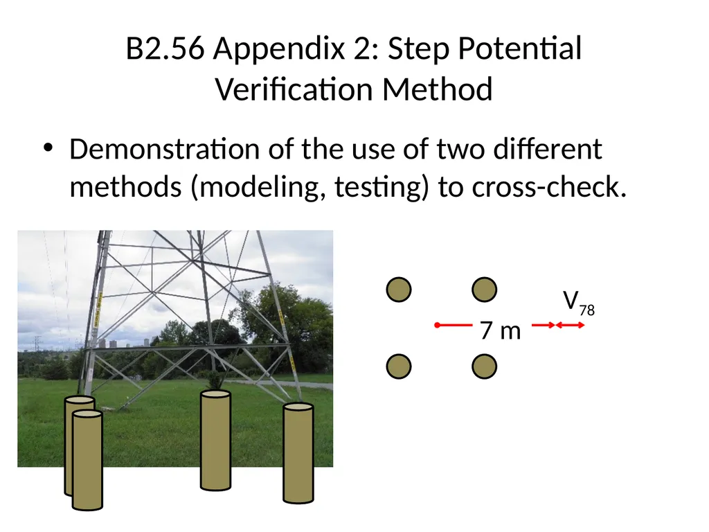
B2.56 Appendix 2: Step Potential Verification Method Demonstration of the use of two different methods (modeling, testing) to cross-check. V78 7 m<br>
07
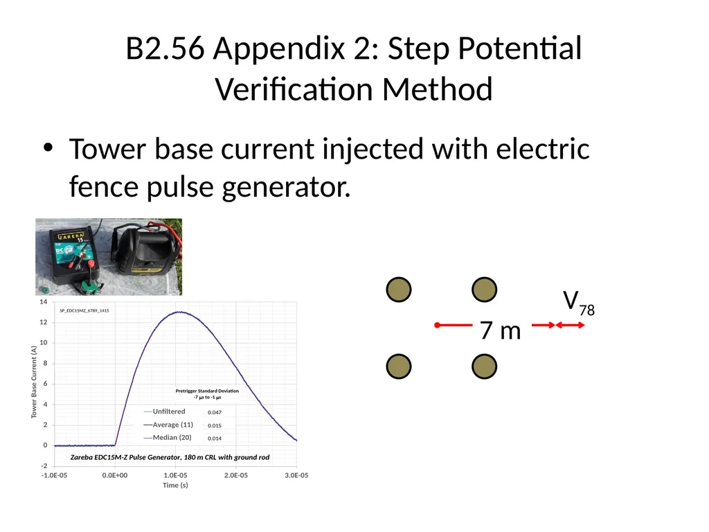
B2.56 Appendix 2: Step Potential Verification Method Tower base current injected with electric fence pulse generator. V78 7 m<br>
08
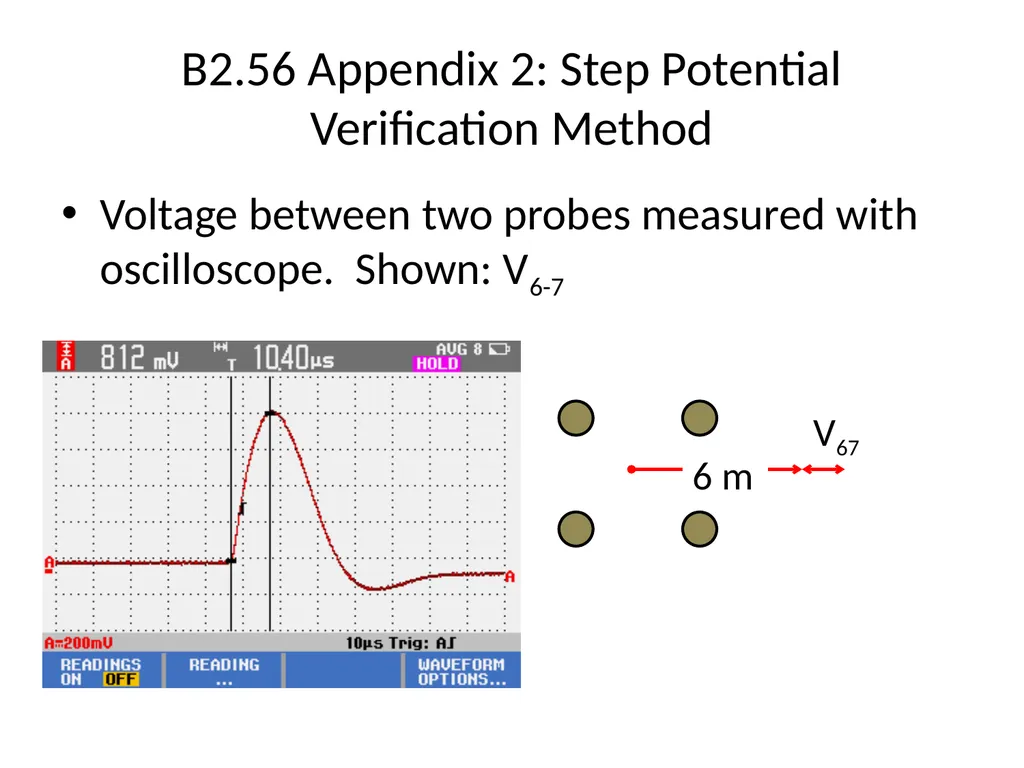
B2.56 Appendix 2: Step Potential Verification Method Voltage between two probes measured with oscilloscope. Shown: V6-7 V67 6 m<br>
09
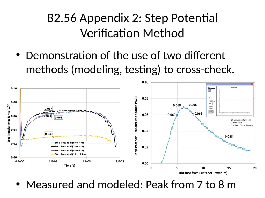
B2.56 Appendix 2: Step Potential Verification Method Demonstration of the use of two different methods (modeling, testing) to cross-check.
Measured and modeled: Peak from 7 to 8 m<br>
Measured and modeled: Peak from 7 to 8 m<br>
10
B2.56 Appendix 2: Step Potential Verification Method Conclusions:
Cross check of field test to calculation is mandatory.
Uniform soil assumption worked here in spite of complex infrastructure (sewer, pipelines) nearby.
Recommendations:
Coordinate with C4.33 to confirm the validity of the impulse test method, considering frequency dependence of the soil.
Evaluate range of two-layer soil contrast (reflection coefficient) for which inverse distance / quasi-uniform soil model is valid.<br>
Cross check of field test to calculation is mandatory.
Uniform soil assumption worked here in spite of complex infrastructure (sewer, pipelines) nearby.
Recommendations:
Coordinate with C4.33 to confirm the validity of the impulse test method, considering frequency dependence of the soil.
Evaluate range of two-layer soil contrast (reflection coefficient) for which inverse distance / quasi-uniform soil model is valid.<br>
11
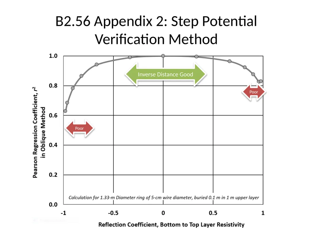
B2.56 Appendix 2: Step Potential Verification Method Inverse Distance Good Poor Poor<br>
12
Meetings Attended Montreal, May 2016
B2.56, Ground Potential Rise at Overhead AC Transmission Line Structures during Power Frequency Faults
B2.AG06.TF007, Don’t Put your Arresters near our Dampers
Petrache paper on CEATI studies (CDEGS HiFreq vs NEC-4)
Lots of interest in German Hybrid AC/DC with positive pole exposed to lightning<br>
B2.56, Ground Potential Rise at Overhead AC Transmission Line Structures during Power Frequency Faults
B2.AG06.TF007, Don’t Put your Arresters near our Dampers
Petrache paper on CEATI studies (CDEGS HiFreq vs NEC-4)
Lots of interest in German Hybrid AC/DC with positive pole exposed to lightning<br>
13
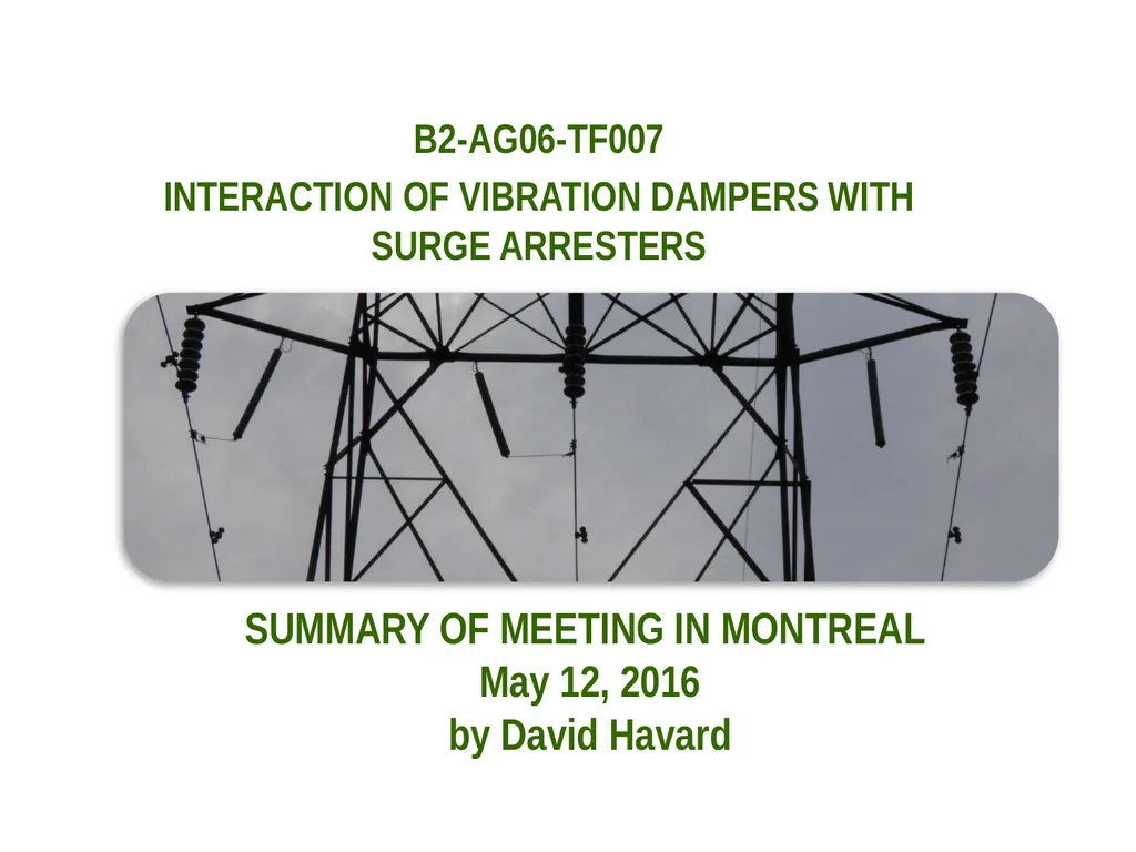
B2-AG06-TF007
INTERACTION OF VIBRATION DAMPERS WITH SURGE ARRESTERS SUMMARY OF MEETING IN MONTREAL
May 12, 2016
by David Havard<br>
INTERACTION OF VIBRATION DAMPERS WITH SURGE ARRESTERS SUMMARY OF MEETING IN MONTREAL
May 12, 2016
by David Havard<br>
14
Havard, B2 AG 06 TF.007 14 SCOPE OF TF007:
Most transmission line surge arrester (TLSA) installations are fitted after construction to improve lightning performance.
Surge arresters are large, heavy and often placed on conductors outside vibration damper locations.
The objective is to produce a paper for CIGRE Journal of Science and Engineering guideline.<br>
Most transmission line surge arrester (TLSA) installations are fitted after construction to improve lightning performance.
Surge arresters are large, heavy and often placed on conductors outside vibration damper locations.
The objective is to produce a paper for CIGRE Journal of Science and Engineering guideline.<br>
15
Havard, B2 AG 06 TF.007 15 SCOPE OF TF007 (CONT’D):
Scheduled completion 2016.
Originally on application of dampers to retain aeolian vibration control for surge arresters applications.
Based on inputs from WG members, now includes other vibration modes and other forms of failure.<br>
Scheduled completion 2016.
Originally on application of dampers to retain aeolian vibration control for surge arresters applications.
Based on inputs from WG members, now includes other vibration modes and other forms of failure.<br>
16
Meeting of May 12 2016
23 Members and guests in attendance:
Agenda included:
Outlining points added to the paper since the last meeting
Review of new material contributed by email in the last week
Furtado re failure of support for TLSA
Vingradov re explosive failure of TLSA and need for Standard Havard, B2 AG 06 TF.00v 16<br>
23 Members and guests in attendance:
Agenda included:
Outlining points added to the paper since the last meeting
Review of new material contributed by email in the last week
Furtado re failure of support for TLSA
Vingradov re explosive failure of TLSA and need for Standard Havard, B2 AG 06 TF.00v 16<br>
17
A review of the 6th draft of the paper
Highlighting key points in the paper
new experiences offered by members present
Van Dyke re use of AGS clamp support
Halsan re loosened corona ring on TLSA
Chisholm re damage to supporting chain Havard, B2 AG 06 TF.007 17<br>
Highlighting key points in the paper
new experiences offered by members present
Van Dyke re use of AGS clamp support
Halsan re loosened corona ring on TLSA
Chisholm re damage to supporting chain Havard, B2 AG 06 TF.007 17<br>
18
Future activities:
Update paper with recently acquired and other new material
Target date within one month
Next (final?) meeting in Paris (Boulogne) in August 2016 Havard, B2 AG 06 TF.007 18<br>
Update paper with recently acquired and other new material
Target date within one month
Next (final?) meeting in Paris (Boulogne) in August 2016 Havard, B2 AG 06 TF.007 18<br>
19
AUTHOR: DR. DAVID G. HAVARD
CONVENOR CIGRE B2-AG06 TF007 PRESIDENT, HAVARD ENGINEERING INC. TEL: 1-905-273-3076, E-MAIL: dhavard@rogers.com WEB PAGE: www.havardengineering.com ADDRESS: 3142 LINDENLEA DRIVE, MISSISSAUGA, ONTARIO, CANADA, L5C 2C2 Havard, B2 AG 06 TF.007 19<br>
CONVENOR CIGRE B2-AG06 TF007 PRESIDENT, HAVARD ENGINEERING INC. TEL: 1-905-273-3076, E-MAIL: dhavard@rogers.com WEB PAGE: www.havardengineering.com ADDRESS: 3142 LINDENLEA DRIVE, MISSISSAUGA, ONTARIO, CANADA, L5C 2C2 Havard, B2 AG 06 TF.007 19<br>
20
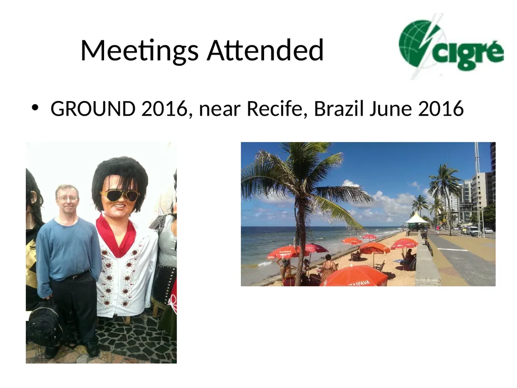
Meetings Attended GROUND 2016, near Recife, Brazil June 2016<br>
21
Meetings Attended GROUND 2016, Brazil June 2016
C4.23, Guide to Procedures for Estimating the Lightning Performance of Transmission Lines
C4.33, Impact of Soil-Parameter Frequency Dependence on the Response of Grounding Electrodes and on the Lightning Performance of Electrical Systems
XIII SIPDA, Brazil, September, 2015
C4.36, Winter Lightning: Parameters and Engineering Consequences for Wind Turbines
C4.410 TB 633, Lightning Striking Characteristics to Very High Structures – Published October 2015<br>
C4.23, Guide to Procedures for Estimating the Lightning Performance of Transmission Lines
C4.33, Impact of Soil-Parameter Frequency Dependence on the Response of Grounding Electrodes and on the Lightning Performance of Electrical Systems
XIII SIPDA, Brazil, September, 2015
C4.36, Winter Lightning: Parameters and Engineering Consequences for Wind Turbines
C4.410 TB 633, Lightning Striking Characteristics to Very High Structures – Published October 2015<br>
22
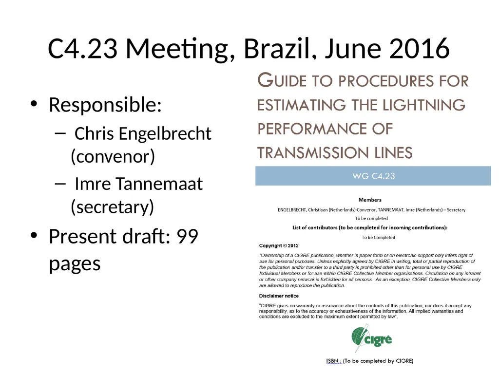
C4.23 Meeting, Brazil, June 2016 Responsible:
Chris Engelbrecht (convenor)
Imre Tannemaat (secretary)
Present draft: 99 pages<br>
Chris Engelbrecht (convenor)
Imre Tannemaat (secretary)
Present draft: 99 pages<br>
23
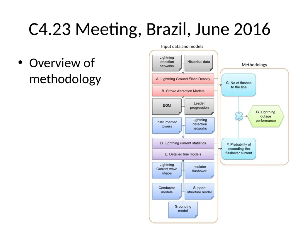
C4.23 Meeting, Brazil, June 2016 Overview of methodology<br>
24
Meetings Attended GROUND 2016, Brazil June 2016
C4.23, Guide to Procedures for Estimating the Lightning Performance of Transmission Lines
C4.33, Impact of Soil-Parameter Frequency Dependence on the Response of Grounding Electrodes and on the Lightning Performance of Electrical Systems
XIII SIPDA, Brazil, September, 2015
C4.36, Winter Lightning: Parameters and Engineering Consequences for Wind Turbines
C4.410 TB 633, Lightning Striking Characteristics to Very High Structures – Published October 2015<br>
C4.23, Guide to Procedures for Estimating the Lightning Performance of Transmission Lines
C4.33, Impact of Soil-Parameter Frequency Dependence on the Response of Grounding Electrodes and on the Lightning Performance of Electrical Systems
XIII SIPDA, Brazil, September, 2015
C4.36, Winter Lightning: Parameters and Engineering Consequences for Wind Turbines
C4.410 TB 633, Lightning Striking Characteristics to Very High Structures – Published October 2015<br>
25
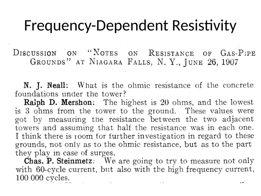
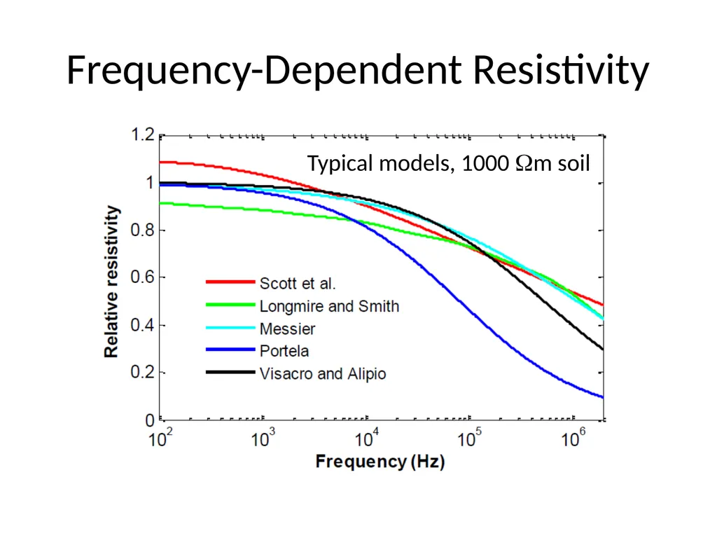
Frequency-Dependent Resistivity Resistivity at 100 kHz or 1 MHz is significantly lower than resistivity measured at 100 Hz
Effect is strongest for high soil resistivity
Effect is well supported by test data<br>
Effect is strongest for high soil resistivity
Effect is well supported by test data<br>
26
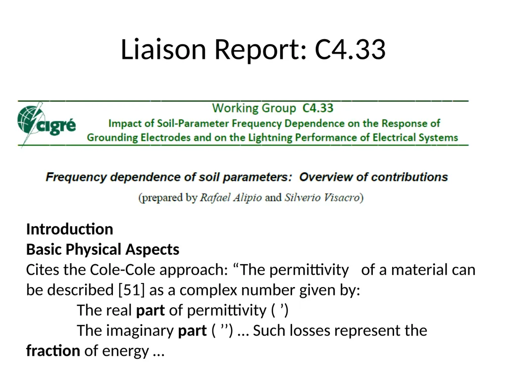
Liaison Report: C4.33 Introduction
Basic Physical Aspects
Cites the Cole-Cole approach: “The permittivity of a material can be described [51] as a complex number given by:
The real part of permittivity (’)
The imaginary part (’’) … Such losses represent the fraction of energy …<br>
Basic Physical Aspects
Cites the Cole-Cole approach: “The permittivity of a material can be described [51] as a complex number given by:
The real part of permittivity (’)
The imaginary part (’’) … Such losses represent the fraction of energy …<br>
27
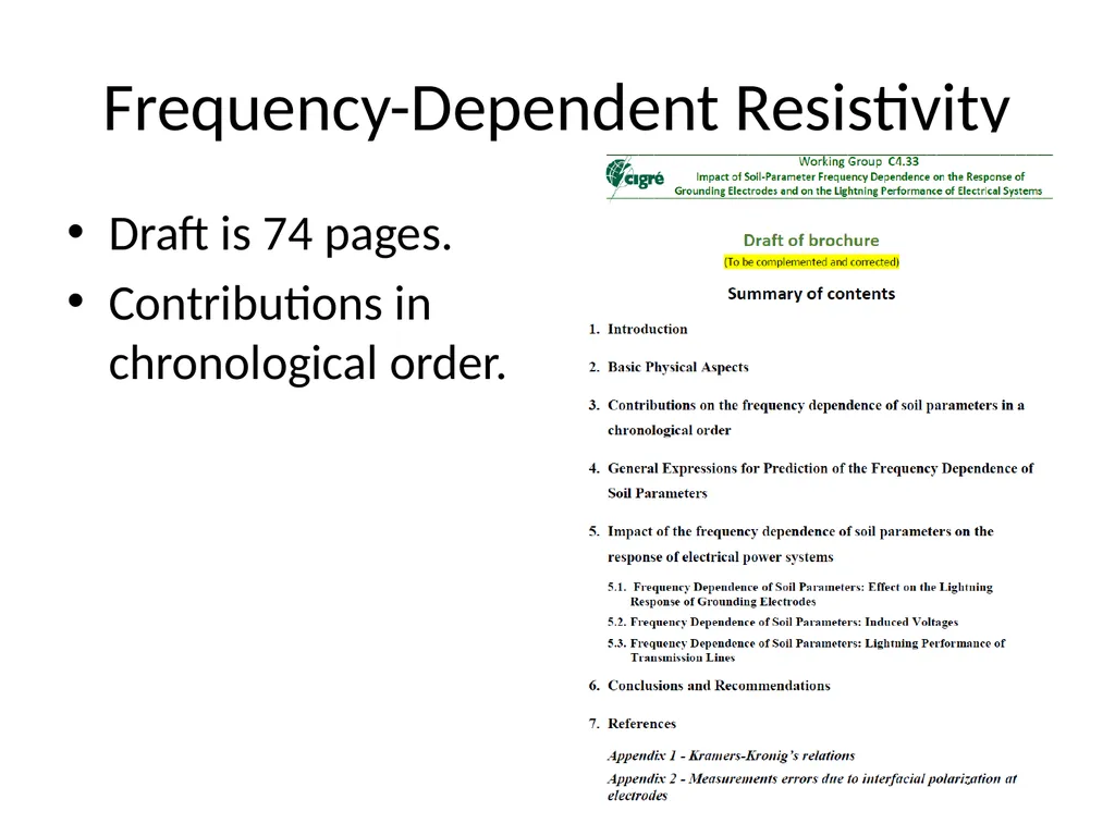
Frequency-Dependent Resistivity Draft is 74 pages.
Contributions in chronological order.<br>
Contributions in chronological order.<br>
28
Frequency-Dependent Resistivity<br>
29
Frequency-Dependent Resistivity Typical models, 1000 m soil<br>
30
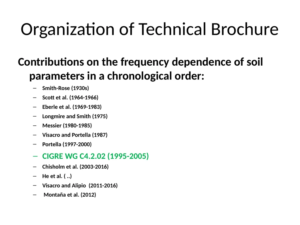
Organization of Technical Brochure Contributions on the frequency dependence of soil parameters in a chronological order:
Smith-Rose (1930s)
Scott et al. (1964-1966)
Eberle et al. (1969-1983)
Longmire and Smith (1975)
Messier (1980-1985)
Visacro and Portella (1987)
Portella (1997-2000)
CIGRE WG C4.2.02 (1995-2005)
Chisholm et al. (2003-2016)
He et al. ( ..)
Visacro and Alipio (2011-2016)
Montaña et al. (2012)<br>
Smith-Rose (1930s)
Scott et al. (1964-1966)
Eberle et al. (1969-1983)
Longmire and Smith (1975)
Messier (1980-1985)
Visacro and Portella (1987)
Portella (1997-2000)
CIGRE WG C4.2.02 (1995-2005)
Chisholm et al. (2003-2016)
He et al. ( ..)
Visacro and Alipio (2011-2016)
Montaña et al. (2012)<br>
31
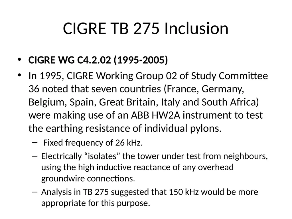
CIGRE TB 275 Inclusion CIGRE WG C4.2.02 (1995-2005)
In 1995, CIGRE Working Group 02 of Study Committee 36 noted that seven countries (France, Germany, Belgium, Spain, Great Britain, Italy and South Africa) were making use of an ABB HW2A instrument to test the earthing resistance of individual pylons.
Fixed frequency of 26 kHz.
Electrically “isolates” the tower under test from neighbours, using the high inductive reactance of any overhead groundwire connections.
Analysis in TB 275 suggested that 150 kHz would be more appropriate for this purpose.<br>
In 1995, CIGRE Working Group 02 of Study Committee 36 noted that seven countries (France, Germany, Belgium, Spain, Great Britain, Italy and South Africa) were making use of an ABB HW2A instrument to test the earthing resistance of individual pylons.
Fixed frequency of 26 kHz.
Electrically “isolates” the tower under test from neighbours, using the high inductive reactance of any overhead groundwire connections.
Analysis in TB 275 suggested that 150 kHz would be more appropriate for this purpose.<br>
32
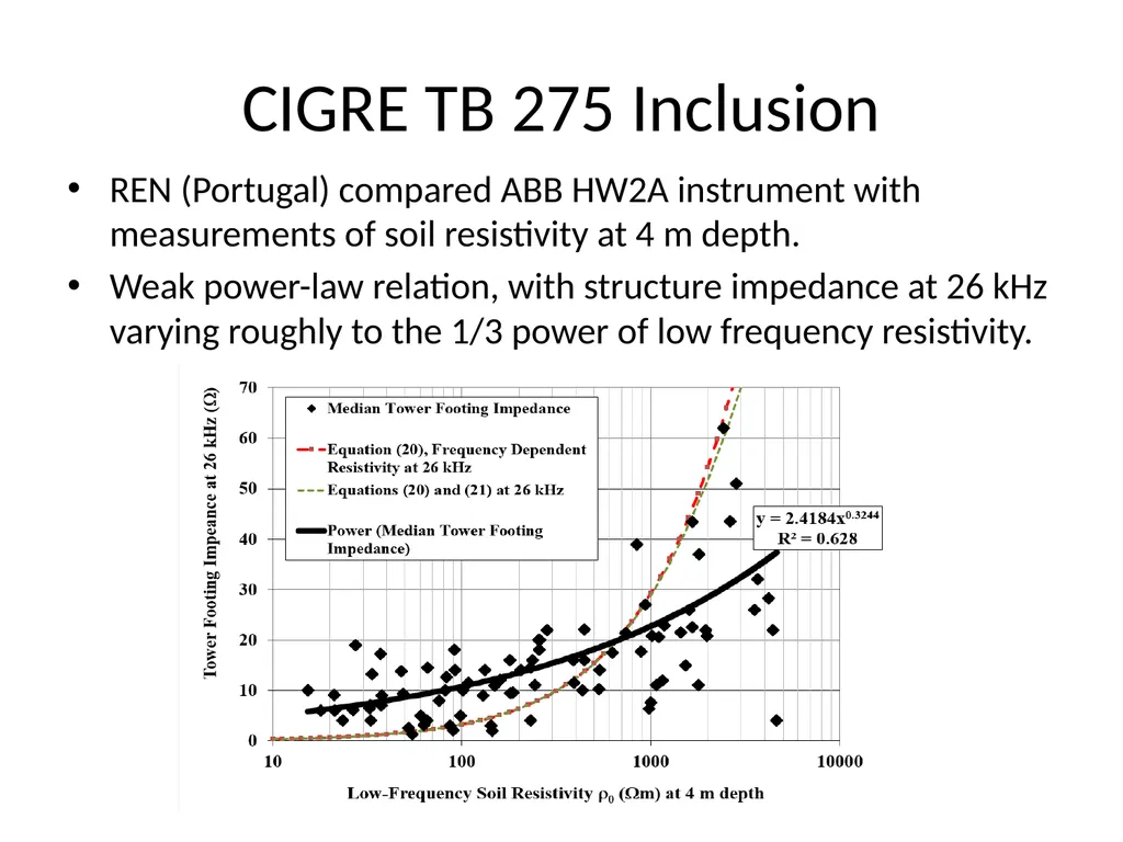
CIGRE TB 275 Inclusion REN (Portugal) compared ABB HW2A instrument with measurements of soil resistivity at 4 m depth.
Weak power-law relation, with structure impedance at 26 kHz varying roughly to the 1/3 power of low frequency resistivity.<br>
Weak power-law relation, with structure impedance at 26 kHz varying roughly to the 1/3 power of low frequency resistivity.<br>
33
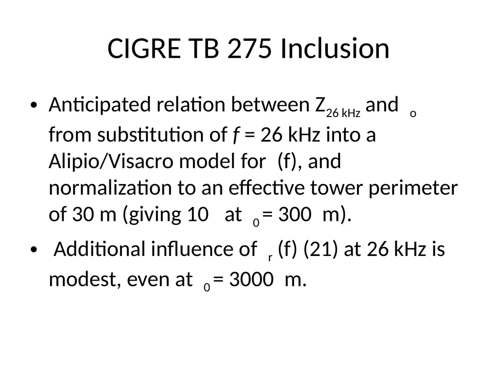
CIGRE TB 275 Inclusion Anticipated relation between Z26 kHz and o from substitution of f = 26 kHz into a Alipio/Visacro model for (f), and normalization to an effective tower perimeter of 30 m (giving 10 at 0 = 300 m).
Additional influence of r (f) (21) at 26 kHz is modest, even at 0 = 3000 m.<br>
Additional influence of r (f) (21) at 26 kHz is modest, even at 0 = 3000 m.<br>
34
Time-Dependent Effects<br>
35
Resistivity vs time, 500 to 1000 ns<br>
36
(f) Versus Ionization Effect on peak tower base voltage
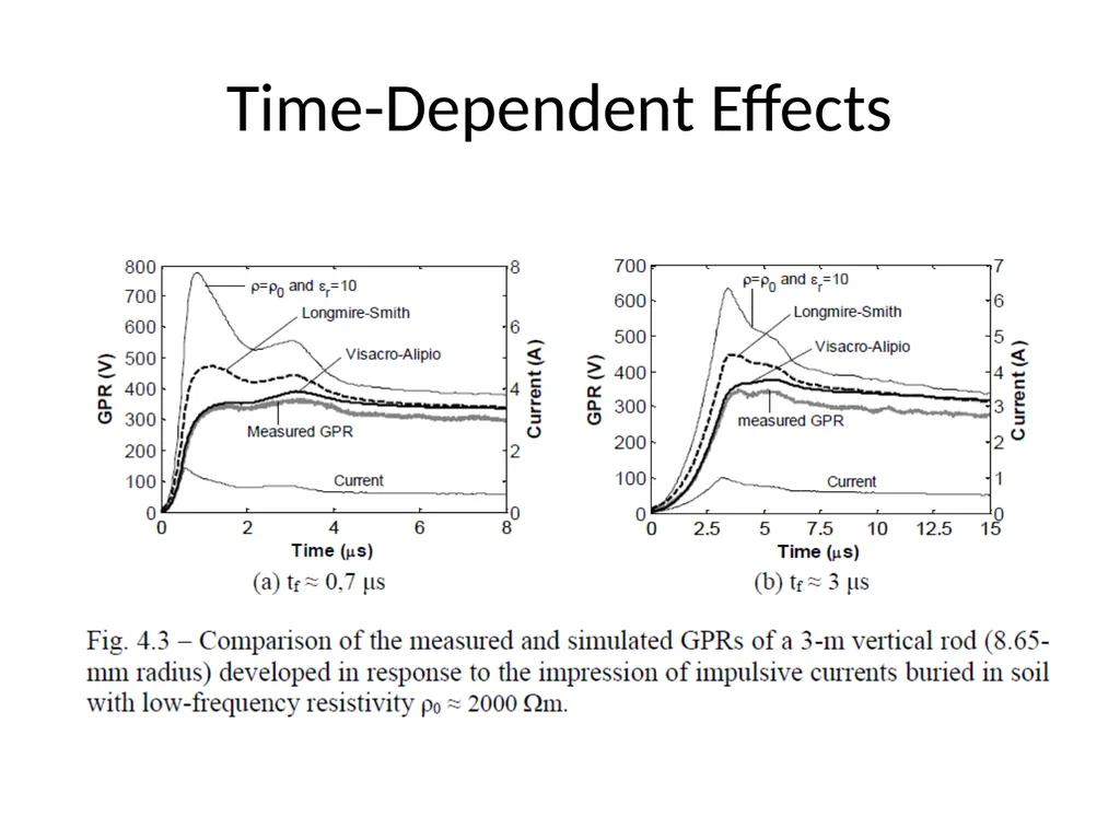
(f) effect is strong initially, weaker by about 2 s
Ionization models introduce onset time constants on the order of 2 s
Effect on large-dimension footings
(f) effect is the same, large or small dimension
Ionization is not so important for footings of transmission lines, compared to single rods
Testability in full scale
(f) effect is easy to verify with 1-10 A test current
Ionization calls for impulse currents of 30 to 200 kA<br>
(f) effect is strong initially, weaker by about 2 s
Ionization models introduce onset time constants on the order of 2 s
Effect on large-dimension footings
(f) effect is the same, large or small dimension
Ionization is not so important for footings of transmission lines, compared to single rods
Testability in full scale
(f) effect is easy to verify with 1-10 A test current
Ionization calls for impulse currents of 30 to 200 kA<br>
37
Meetings Attended PES Annual Meeting, July 2016
HVDC Line Design Guide Task Force (July 18)
HVDC Line Design Subcommittee (July 20, 8 AM)<br>
HVDC Line Design Guide Task Force (July 18)
HVDC Line Design Subcommittee (July 20, 8 AM)<br>
38
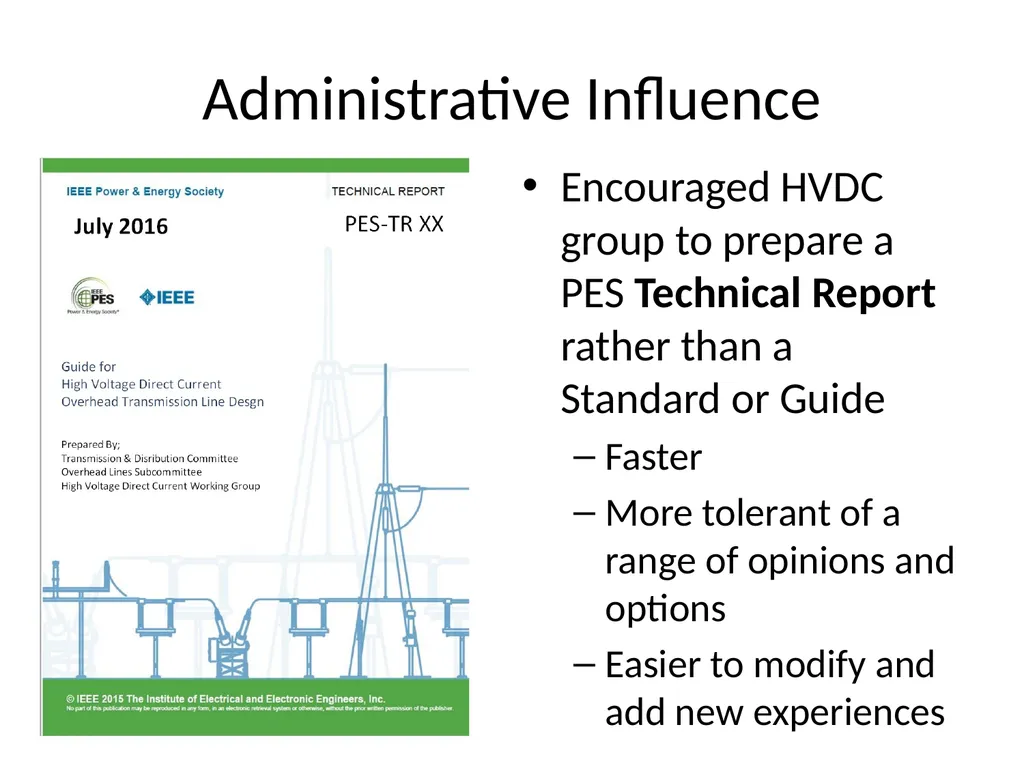
Administrative Influence Encouraged HVDC group to prepare a PES Technical Report rather than a Standard or Guide
Faster
More tolerant of a range of opinions and options
Easier to modify and add new experiences<br>
Faster
More tolerant of a range of opinions and options
Easier to modify and add new experiences<br>
39
Technical Influence – Chapter 3.4 Grounding – considered as “return electrode”
HVDC should always be designed with Overhead Groundwires (OHGW), never unshielded.
Role of end-to-end optical fiber cable.
Expected dc resistance of OHGW as line return electrode
0.25 for length > 60 km with 9/16” aluminum clad steel
0.03 for length > 300 km with 336 kcmil Linnet ACSR
Introduces Insulated Earth Return Wire (below phases)
Foundation grounding issues – expected relation to soil resistivity; corrosion aspects; two-layer soil case.
Worst case: Separate return electrode (Appendix C) in domain of Substation Committee (Guide 80, Guide 81).<br>
HVDC should always be designed with Overhead Groundwires (OHGW), never unshielded.
Role of end-to-end optical fiber cable.
Expected dc resistance of OHGW as line return electrode
0.25 for length > 60 km with 9/16” aluminum clad steel
0.03 for length > 300 km with 336 kcmil Linnet ACSR
Introduces Insulated Earth Return Wire (below phases)
Foundation grounding issues – expected relation to soil resistivity; corrosion aspects; two-layer soil case.
Worst case: Separate return electrode (Appendix C) in domain of Substation Committee (Guide 80, Guide 81).<br>
40
Technical Influence – Chapter 3.5 Lightning – role of dc voltage bias
Positive pole adds to stress from negative lightning to tower, so it has lower “critical current” and thus higher backflashover rate.
Use critical current of negative-pole backflashover to estimate the two-pole to ground fault rate.<br>
Positive pole adds to stress from negative lightning to tower, so it has lower “critical current” and thus higher backflashover rate.
Use critical current of negative-pole backflashover to estimate the two-pole to ground fault rate.<br>
41
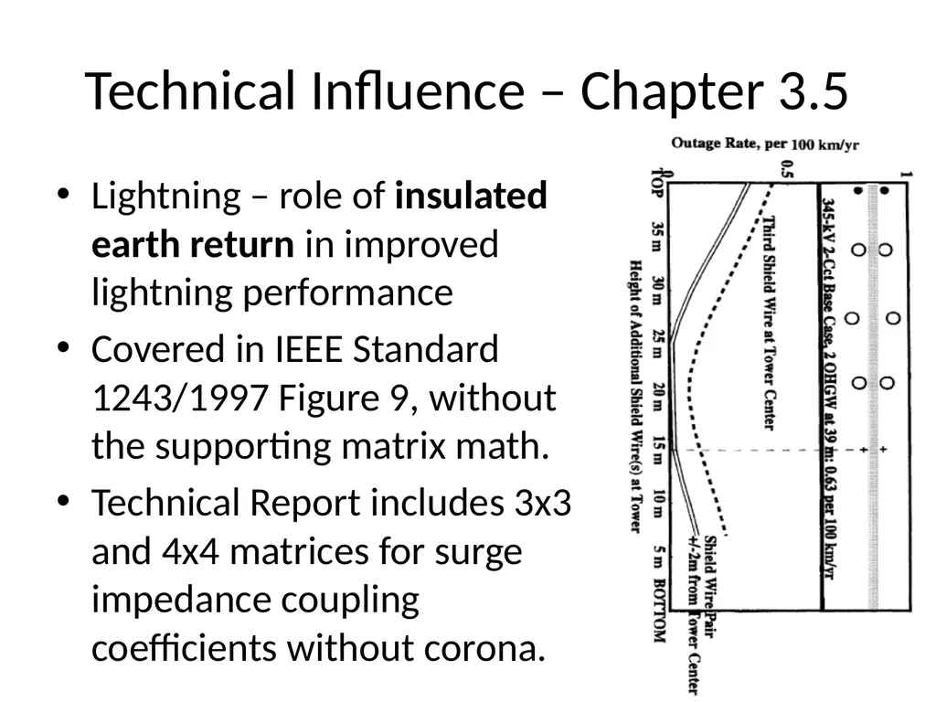
Technical Influence – Chapter 3.5 Lightning – role of insulated earth return in improved lightning performance
Covered in IEEE Standard 1243/1997 Figure 9, without the supporting matrix math.
Technical Report includes 3x3 and 4x4 matrices for surge impedance coupling coefficients without corona.<br>
Covered in IEEE Standard 1243/1997 Figure 9, without the supporting matrix math.
Technical Report includes 3x3 and 4x4 matrices for surge impedance coupling coefficients without corona.<br>
42
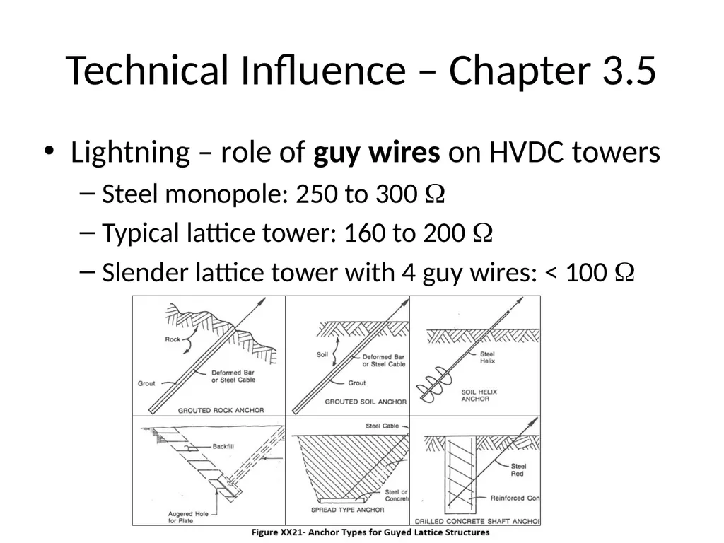
Technical Influence – Chapter 3.5 Lightning – role of guy wires on HVDC towers
Steel monopole: 250 to 300
Typical lattice tower: 160 to 200
Slender lattice tower with 4 guy wires: < 100 <br>
Steel monopole: 250 to 300
Typical lattice tower: 160 to 200
Slender lattice tower with 4 guy wires: < 100 <br>
43
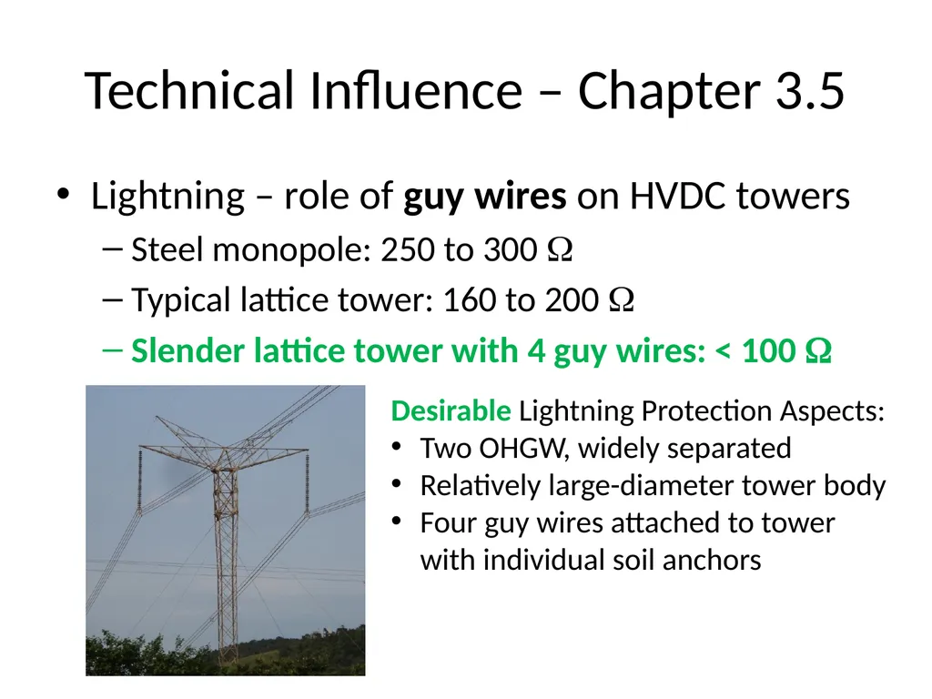
Technical Influence – Chapter 3.5 Lightning – role of guy wires on HVDC towers
Steel monopole: 250 to 300
Typical lattice tower: 160 to 200
Slender lattice tower with 4 guy wires: < 100 Desirable Lightning Protection Aspects:
Two OHGW, widely separated
Relatively large-diameter tower body
Four guy wires attached to tower with individual soil anchors<br>
Steel monopole: 250 to 300
Typical lattice tower: 160 to 200
Slender lattice tower with 4 guy wires: < 100 Desirable Lightning Protection Aspects:
Two OHGW, widely separated
Relatively large-diameter tower body
Four guy wires attached to tower with individual soil anchors<br>
44
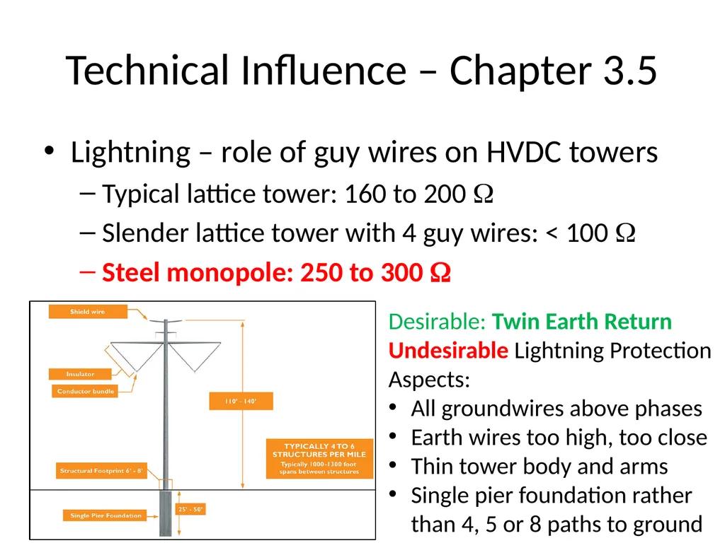
Technical Influence – Chapter 3.5 Lightning – role of guy wires on HVDC towers
Typical lattice tower: 160 to 200
Slender lattice tower with 4 guy wires: < 100
Steel monopole: 250 to 300 Desirable: Twin Earth Return
Undesirable Lightning Protection Aspects:
All groundwires above phases
Earth wires too high, too close
Thin tower body and arms
Single pier foundation rather than 4, 5 or 8 paths to ground<br>
Typical lattice tower: 160 to 200
Slender lattice tower with 4 guy wires: < 100
Steel monopole: 250 to 300 Desirable: Twin Earth Return
Undesirable Lightning Protection Aspects:
All groundwires above phases
Earth wires too high, too close
Thin tower body and arms
Single pier foundation rather than 4, 5 or 8 paths to ground<br>
45
TR Conclusion / Recommendations Technical Report gives an overview of the specific issues related to HVDC overhead line design and some perspective on the production variations in existing HVDC line designs.
Some weakness and internal consistency can be improved, but it is ready for next-level approval and publication.
Try to avoid the long delay in TR-17 on aeolian vibration, in getting from 99 to 99.9%.<br>
Some weakness and internal consistency can be improved, but it is ready for next-level approval and publication.
Try to avoid the long delay in TR-17 on aeolian vibration, in getting from 99 to 99.9%.<br>