Review: Rate Equation for Enzymatic Reaction
Description: Review: Rate Equation for Enzymatic Reaction Where: Review: Lineweaver-Burk Equation 2 Lineweaver Burk: inverted the MM equation By plotting 1 V vs 1CS, a linear plot is obtained: Slope KmVmax y-intercept 1Vmax x-intercept -1Km
Related Topics
Download Presentation
"Review: Rate Equation for Enzymatic Reaction" is the property of its rightful owner. Permission is granted to download and print the materials on this website for personal, non-commercial use only, and to display it on your personal computer provided you do not modify the materials and that you retain all copyright notices contained in the materials. By downloading content from our website, you accept the terms of this agreement.
Presentation Transcript
slide1. Review: Rate Equation for Enzymatic Reaction Where:<br>
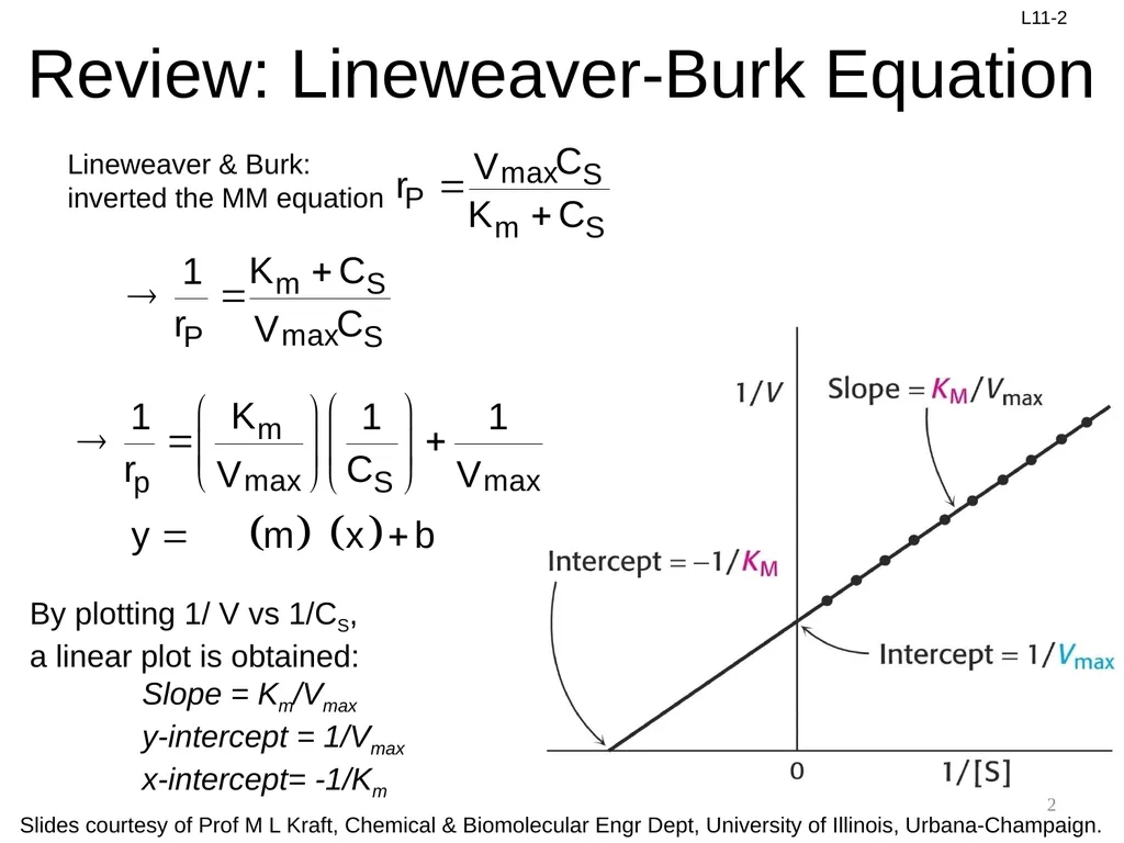
slide2. Review: Lineweaver-Burk Equation 2 Lineweaver & Burk: inverted the MM equation By plotting 1/ V vs 1/CS,
a linear plot is obtained:
Slope = Km/Vmax
y-intercept = 1/Vmax
x-intercept= -1/Km<br>
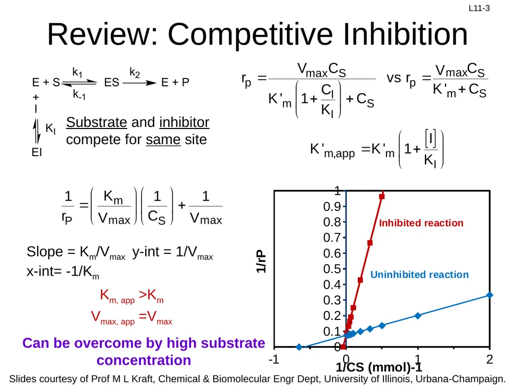
slide3. Review: Competitive Inhibition Slope = Km/Vmax y-int = 1/Vmax
x-int= -1/Km Can be overcome by high substrate concentration Km, app >Km Vmax, app =Vmax<br>
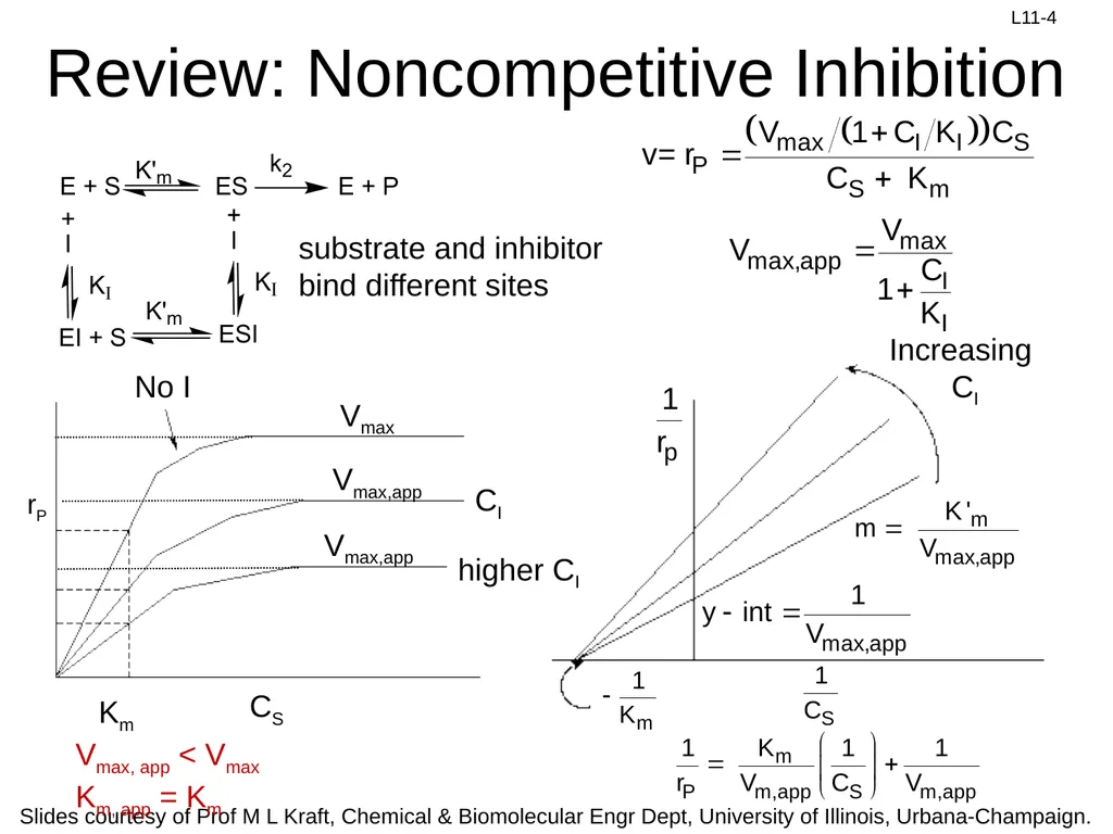
slide4. Review: Noncompetitive Inhibition Vmax, app < Vmax
Km, app = Km substrate and inhibitor bind different sites<br>
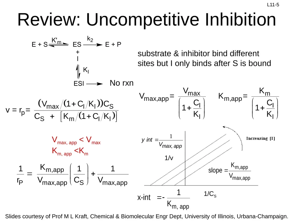
slide5. substrate & inhibitor bind different sites but I only binds after S is bound Vmax, app < Vmax
Km, app <Km No rxn Review: Uncompetitive Inhibition<br>
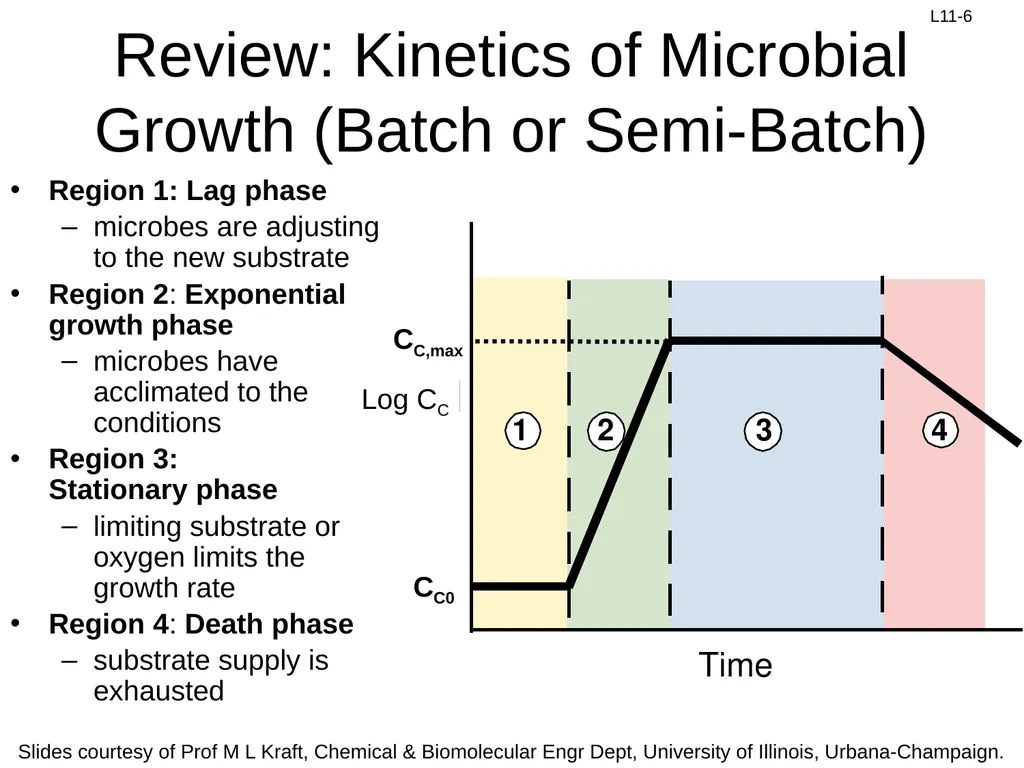
slide6. Region 1: Lag phase
microbes are adjusting to the new substrate
Region 2: Exponential growth phase
microbes have acclimated to the conditions
Region 3: Stationary phase
limiting substrate or oxygen limits the growth rate
Region 4: Death phase
substrate supply is exhausted Review: Kinetics of Microbial Growth (Batch or Semi-Batch) CC,max Log CC CC0<br>
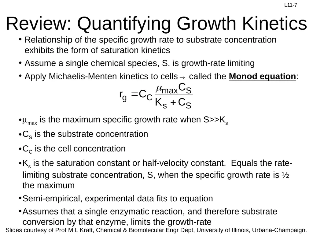
slide7. Review: Quantifying Growth Kinetics Relationship of the specific growth rate to substrate concentration exhibits the form of saturation kinetics
Assume a single chemical species, S, is growth-rate limiting
Apply Michaelis-Menten kinetics to cells→ called the Monod equation: mmax is the maximum specific growth rate when S>>Ks
CS is the substrate concentration
CC is the cell concentration
Ks is the saturation constant or half-velocity constant. Equals the rate-limiting substrate concentration, S, when the specific growth rate is ½ the maximum
Semi-empirical, experimental data fits to equation
Assumes that a single enzymatic reaction, and therefore substrate conversion by that enzyme, limits the growth-rate<br>
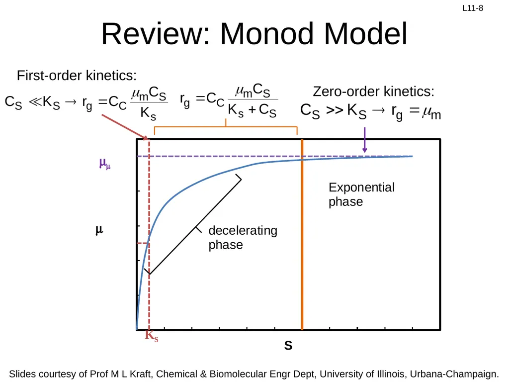
slide8. Review: Monod Model First-order kinetics: Zero-order kinetics:<br>
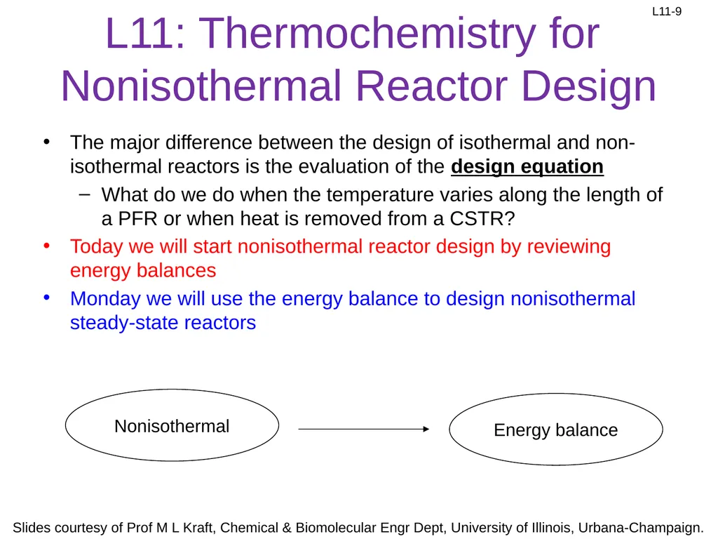
slide9. L11: Thermochemistry for Nonisothermal Reactor Design The major difference between the design of isothermal and non-isothermal reactors is the evaluation of the design equation
What do we do when the temperature varies along the length of a PFR or when heat is removed from a CSTR?
Today we will start nonisothermal reactor design by reviewing energy balances
Monday we will use the energy balance to design nonisothermal steady-state reactors Nonisothermal Energy balance<br>
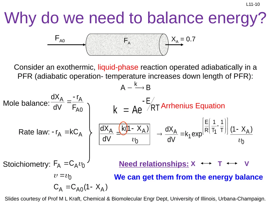
slide10. Why do we need to balance energy? FA XA = 0.7 Mole balance: Rate law: Stoichiometry: Arrhenius Equation Consider an exothermic, liquid-phase reaction operated adiabatically in a PFR (adiabatic operation- temperature increases down length of PFR): FA0 We can get them from the energy balance<br>
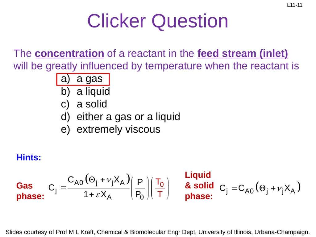
slide11. Clicker Question The concentration of a reactant in the feed stream (inlet) will be greatly influenced by temperature when the reactant is
a gas
a liquid
a solid
either a gas or a liquid
extremely viscous Gas phase: Liquid& solid phase: Hints:<br>
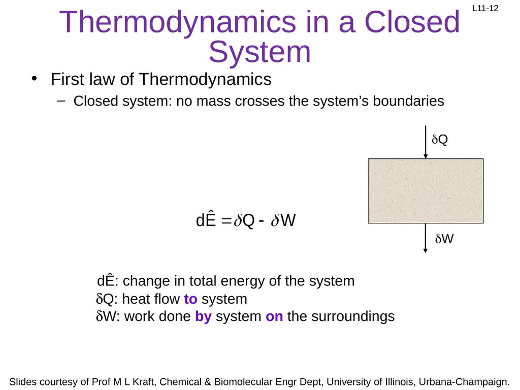
slide12. Thermodynamics in a Closed System First law of Thermodynamics
Closed system: no mass crosses the system’s boundaries dÊ: change in total energy of the system dQ: heat flow to system
dW: work done by system on the surroundings<br>
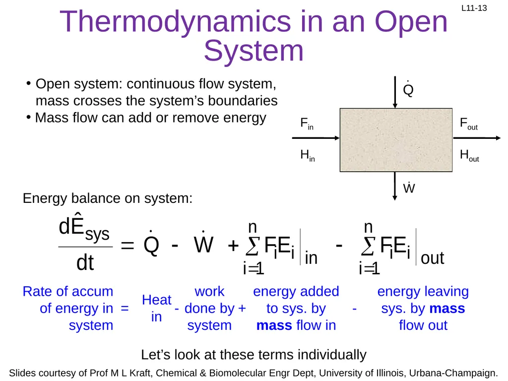
slide13. Thermodynamics in an Open System Open system: continuous flow system, mass crosses the system’s boundaries
Mass flow can add or remove energy Energy balance on system: Let’s look at these terms individually<br>
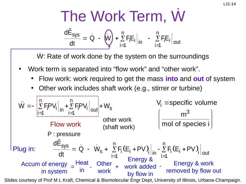
slide14. The Work Term, Ẇ Work term is separated into “flow work” and “other work”.
Flow work: work required to get the mass into and out of system
Other work includes shaft work (e.g., stirrer or turbine) other work (shaft work) P : pressure Ẇ: Rate of work done by the system on the surroundings Flow work Plug in:<br>
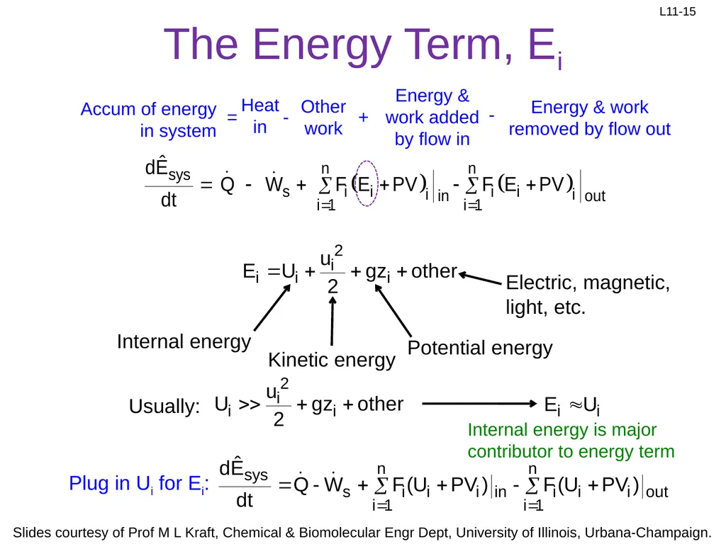
slide15. The Energy Term, Ei Usually: Plug in Ui for Ei: Internal energy is major contributor to energy term<br>
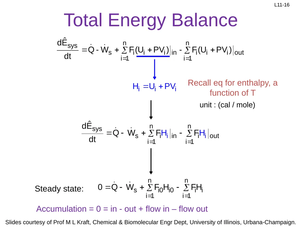
slide16. Recall eq for enthalpy, a function of T unit : (cal / mole) Steady state: Accumulation = 0 = in - out + flow in – flow out Total Energy Balance<br>
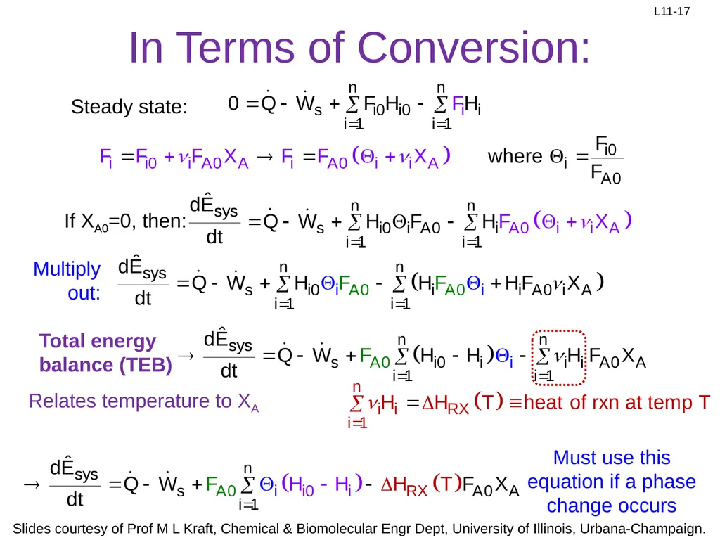
slide17. In Terms of Conversion: If XA0=0, then: Steady state: Total energy balance (TEB) Relates temperature to XA Multiply out: Must use this equation if a phase change occurs<br>
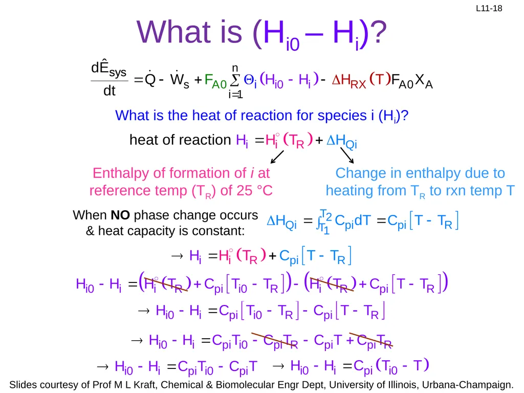
slide18. What is (Hi0 – Hi)? Enthalpy of formation of i at reference temp (TR) of 25 °C What is the heat of reaction for species i (Hi)? Change in enthalpy due to heating from TR to rxn temp T<br>
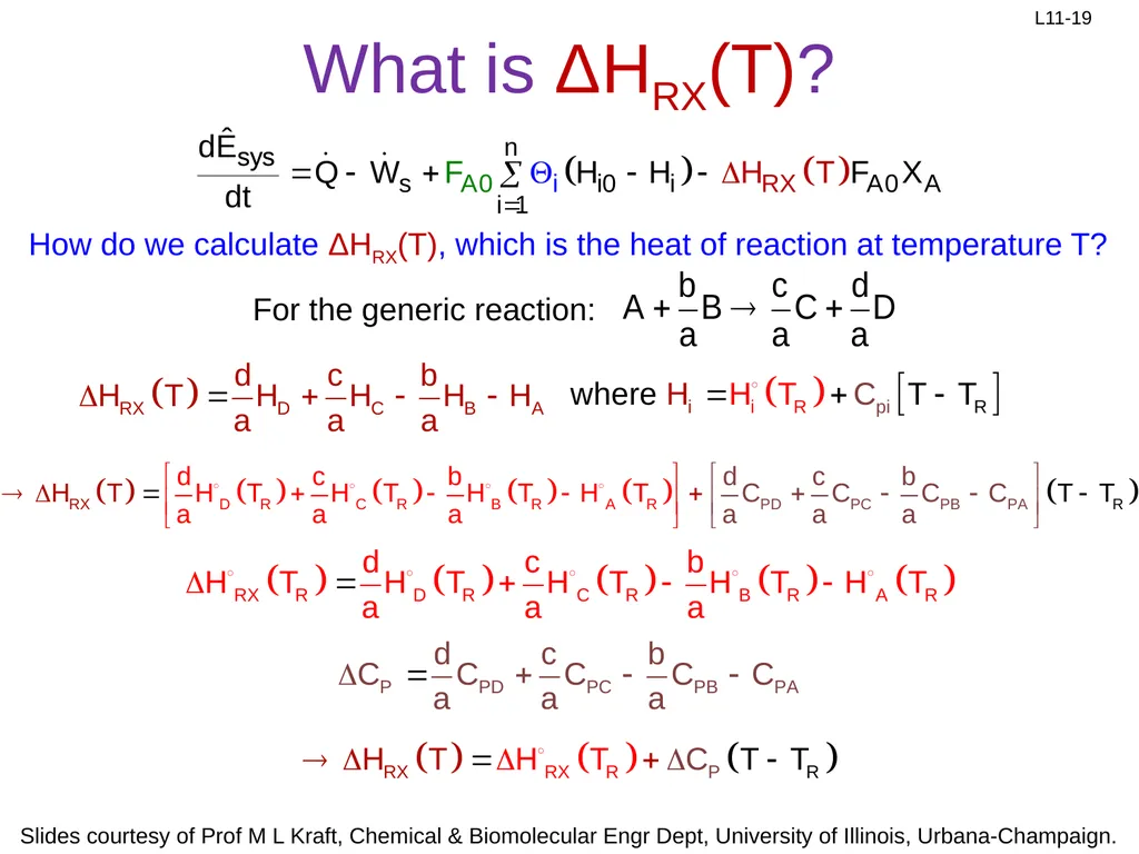
slide19. What is ΔHRX(T)? How do we calculate ΔHRX(T), which is the heat of reaction at temperature T?<br>
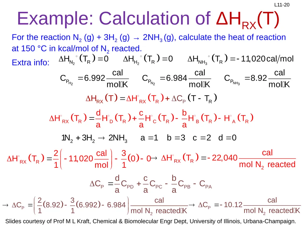
slide20. Example: Calculation of ΔHRX(T) For the reaction N2 (g) + 3H2 (g) → 2NH3 (g), calculate the heat of reaction at 150 °C in kcal/mol of N2 reacted.
Extra info:<br>
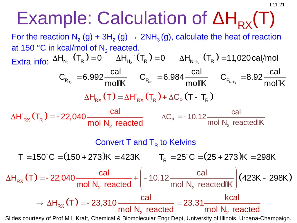
slide21. Example: Calculation of ΔHRX(T) For the reaction N2 (g) + 3H2 (g) → 2NH3 (g), calculate the heat of reaction at 150 °C in kcal/mol of N2 reacted.
Extra info: Convert T and TR to Kelvins<br>
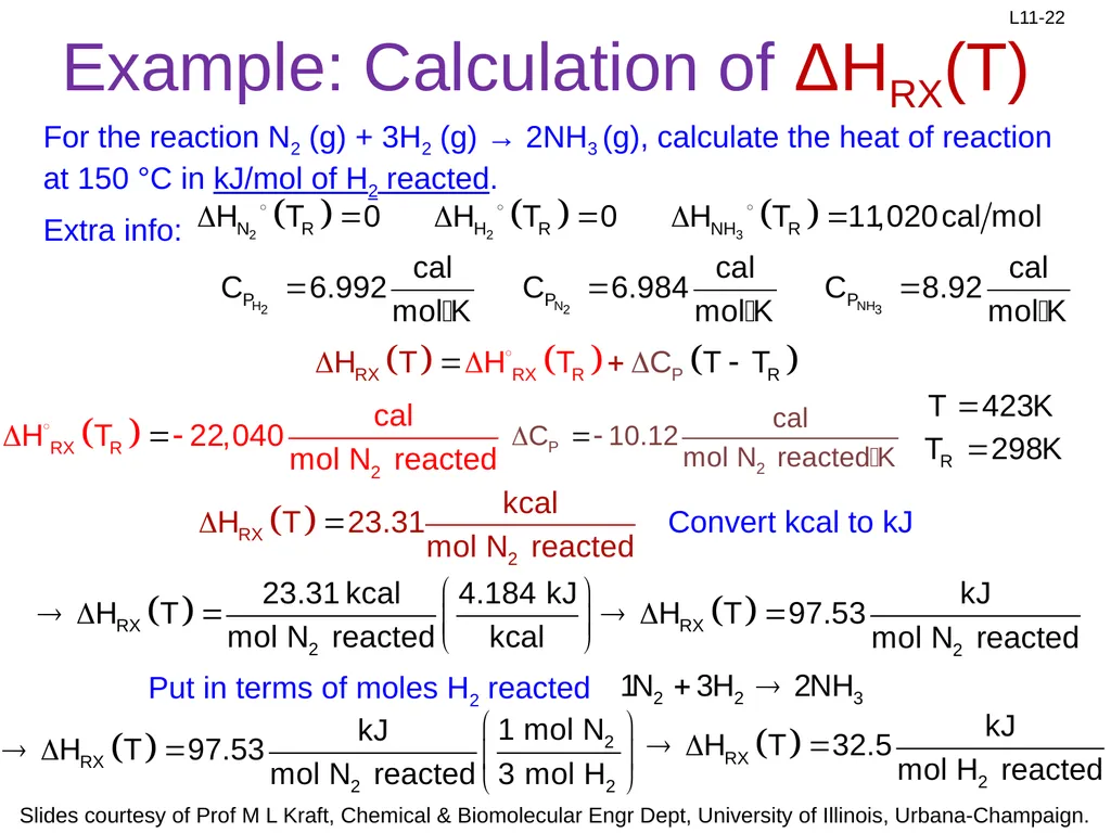
slide22. Example: Calculation of ΔHRX(T) For the reaction N2 (g) + 3H2 (g) → 2NH3 (g), calculate the heat of reaction at 150 °C in kJ/mol of H2 reacted.
Extra info: Convert kcal to kJ Put in terms of moles H2 reacted<br>
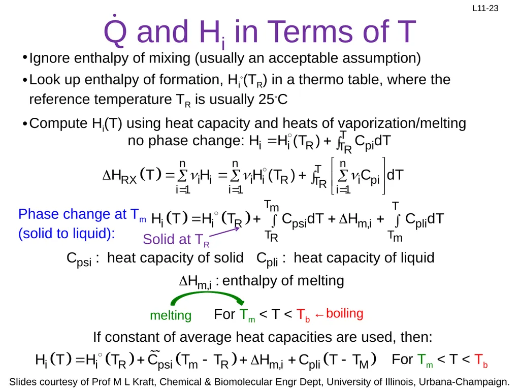
slide23. Q and Hi in Terms of T Ignore enthalpy of mixing (usually an acceptable assumption)
Look up enthalpy of formation, Hi◦(TR) in a thermo table, where the reference temperature TR is usually 25◦C
Compute Hi(T) using heat capacity and heats of vaporization/melting Phase change at Tm (solid to liquid): For Tm < T < Tb ←boiling If constant of average heat capacities are used, then: For Tm < T < Tb<br>
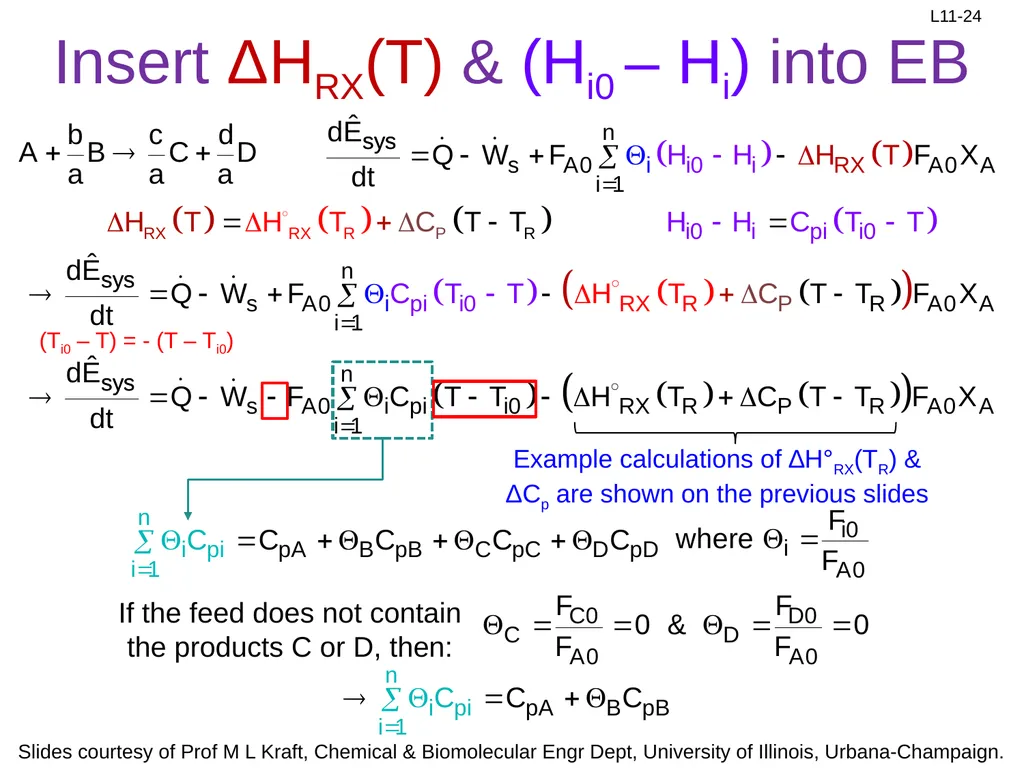
slide24. Insert ΔHRX(T) & (Hi0 – Hi) into EB Example calculations of ∆H°RX(TR) & ΔCp are shown on the previous slides If the feed does not contain the products C or D, then: (Ti0 – T) = - (T – Ti0)<br>
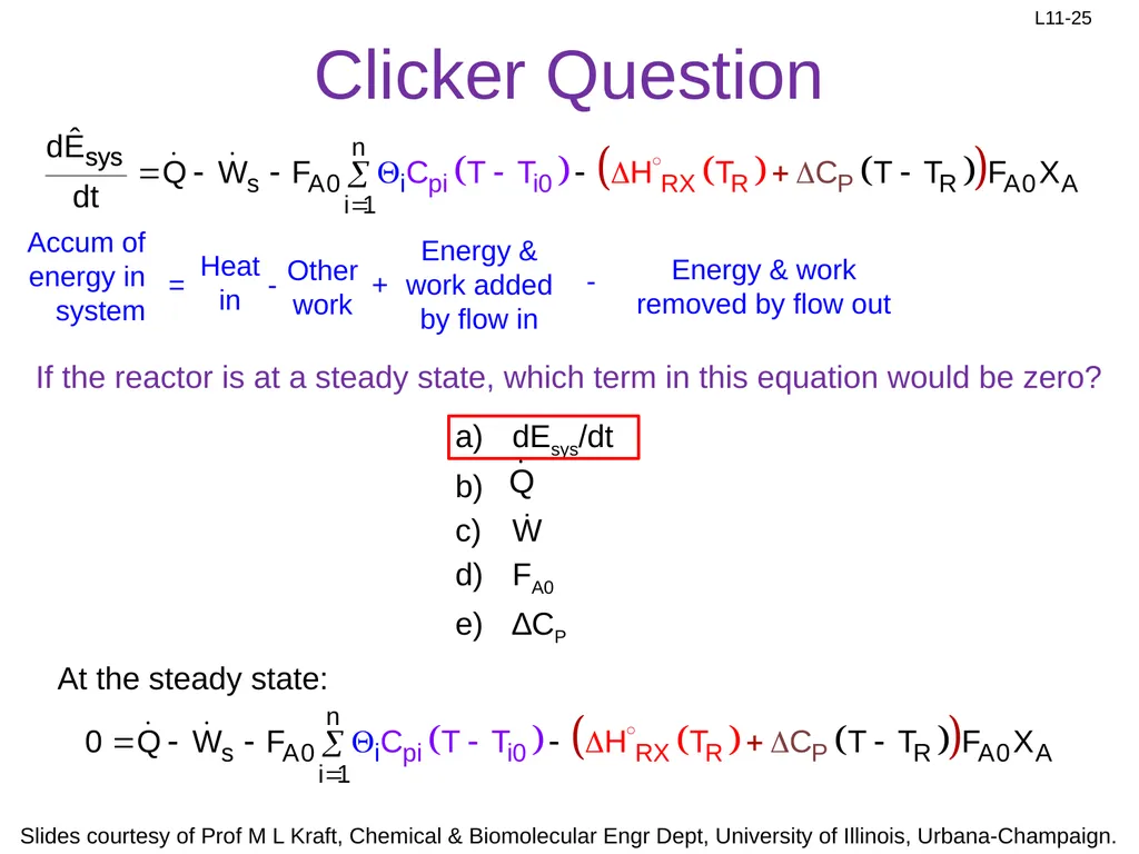
slide25. Clicker Question If the reactor is at a steady state, which term in this equation would be zero? At the steady state:<br>
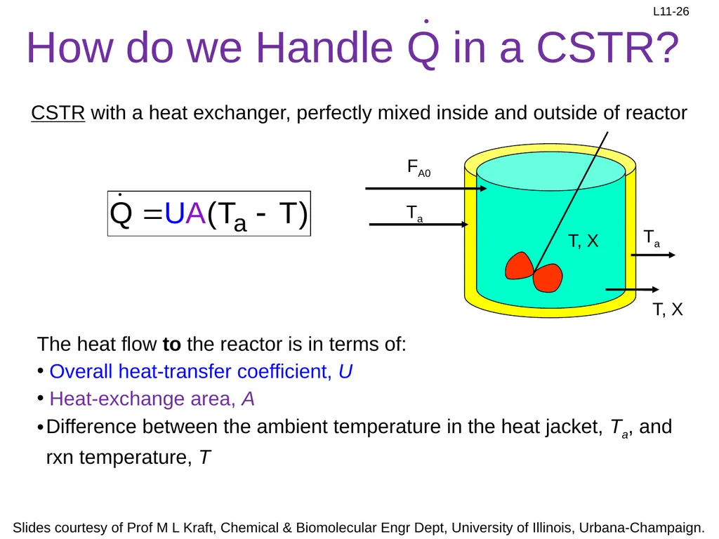
slide26. How do we Handle Q in a CSTR? CSTR with a heat exchanger, perfectly mixed inside and outside of reactor The heat flow to the reactor is in terms of:
Overall heat-transfer coefficient, U
Heat-exchange area, A
Difference between the ambient temperature in the heat jacket, Ta, and rxn temperature, T<br>
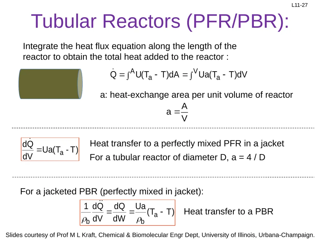
slide27. Integrate the heat flux equation along the length of the reactor to obtain the total heat added to the reactor : Heat transfer to a perfectly mixed PFR in a jacket a: heat-exchange area per unit volume of reactor For a tubular reactor of diameter D, a = 4 / D For a jacketed PBR (perfectly mixed in jacket): Heat transfer to a PBR Tubular Reactors (PFR/PBR):<br>

slide2. Review: Lineweaver-Burk Equation 2 Lineweaver & Burk: inverted the MM equation By plotting 1/ V vs 1/CS,
a linear plot is obtained:
Slope = Km/Vmax
y-intercept = 1/Vmax
x-intercept= -1/Km<br>
slide3. Review: Competitive Inhibition Slope = Km/Vmax y-int = 1/Vmax
x-int= -1/Km Can be overcome by high substrate concentration Km, app >Km Vmax, app =Vmax<br>
slide4. Review: Noncompetitive Inhibition Vmax, app < Vmax
Km, app = Km substrate and inhibitor bind different sites<br>
slide5. substrate & inhibitor bind different sites but I only binds after S is bound Vmax, app < Vmax
Km, app <Km No rxn Review: Uncompetitive Inhibition<br>
slide6. Region 1: Lag phase
microbes are adjusting to the new substrate
Region 2: Exponential growth phase
microbes have acclimated to the conditions
Region 3: Stationary phase
limiting substrate or oxygen limits the growth rate
Region 4: Death phase
substrate supply is exhausted Review: Kinetics of Microbial Growth (Batch or Semi-Batch) CC,max Log CC CC0<br>
slide7. Review: Quantifying Growth Kinetics Relationship of the specific growth rate to substrate concentration exhibits the form of saturation kinetics
Assume a single chemical species, S, is growth-rate limiting
Apply Michaelis-Menten kinetics to cells→ called the Monod equation: mmax is the maximum specific growth rate when S>>Ks
CS is the substrate concentration
CC is the cell concentration
Ks is the saturation constant or half-velocity constant. Equals the rate-limiting substrate concentration, S, when the specific growth rate is ½ the maximum
Semi-empirical, experimental data fits to equation
Assumes that a single enzymatic reaction, and therefore substrate conversion by that enzyme, limits the growth-rate<br>
slide8. Review: Monod Model First-order kinetics: Zero-order kinetics:<br>
slide9. L11: Thermochemistry for Nonisothermal Reactor Design The major difference between the design of isothermal and non-isothermal reactors is the evaluation of the design equation
What do we do when the temperature varies along the length of a PFR or when heat is removed from a CSTR?
Today we will start nonisothermal reactor design by reviewing energy balances
Monday we will use the energy balance to design nonisothermal steady-state reactors Nonisothermal Energy balance<br>
slide10. Why do we need to balance energy? FA XA = 0.7 Mole balance: Rate law: Stoichiometry: Arrhenius Equation Consider an exothermic, liquid-phase reaction operated adiabatically in a PFR (adiabatic operation- temperature increases down length of PFR): FA0 We can get them from the energy balance<br>
slide11. Clicker Question The concentration of a reactant in the feed stream (inlet) will be greatly influenced by temperature when the reactant is
a gas
a liquid
a solid
either a gas or a liquid
extremely viscous Gas phase: Liquid& solid phase: Hints:<br>
slide12. Thermodynamics in a Closed System First law of Thermodynamics
Closed system: no mass crosses the system’s boundaries dÊ: change in total energy of the system dQ: heat flow to system
dW: work done by system on the surroundings<br>
slide13. Thermodynamics in an Open System Open system: continuous flow system, mass crosses the system’s boundaries
Mass flow can add or remove energy Energy balance on system: Let’s look at these terms individually<br>
slide14. The Work Term, Ẇ Work term is separated into “flow work” and “other work”.
Flow work: work required to get the mass into and out of system
Other work includes shaft work (e.g., stirrer or turbine) other work (shaft work) P : pressure Ẇ: Rate of work done by the system on the surroundings Flow work Plug in:<br>
slide15. The Energy Term, Ei Usually: Plug in Ui for Ei: Internal energy is major contributor to energy term<br>
slide16. Recall eq for enthalpy, a function of T unit : (cal / mole) Steady state: Accumulation = 0 = in - out + flow in – flow out Total Energy Balance<br>
slide17. In Terms of Conversion: If XA0=0, then: Steady state: Total energy balance (TEB) Relates temperature to XA Multiply out: Must use this equation if a phase change occurs<br>
slide18. What is (Hi0 – Hi)? Enthalpy of formation of i at reference temp (TR) of 25 °C What is the heat of reaction for species i (Hi)? Change in enthalpy due to heating from TR to rxn temp T<br>
slide19. What is ΔHRX(T)? How do we calculate ΔHRX(T), which is the heat of reaction at temperature T?<br>
slide20. Example: Calculation of ΔHRX(T) For the reaction N2 (g) + 3H2 (g) → 2NH3 (g), calculate the heat of reaction at 150 °C in kcal/mol of N2 reacted.
Extra info:<br>
slide21. Example: Calculation of ΔHRX(T) For the reaction N2 (g) + 3H2 (g) → 2NH3 (g), calculate the heat of reaction at 150 °C in kcal/mol of N2 reacted.
Extra info: Convert T and TR to Kelvins<br>
slide22. Example: Calculation of ΔHRX(T) For the reaction N2 (g) + 3H2 (g) → 2NH3 (g), calculate the heat of reaction at 150 °C in kJ/mol of H2 reacted.
Extra info: Convert kcal to kJ Put in terms of moles H2 reacted<br>
slide23. Q and Hi in Terms of T Ignore enthalpy of mixing (usually an acceptable assumption)
Look up enthalpy of formation, Hi◦(TR) in a thermo table, where the reference temperature TR is usually 25◦C
Compute Hi(T) using heat capacity and heats of vaporization/melting Phase change at Tm (solid to liquid): For Tm < T < Tb ←boiling If constant of average heat capacities are used, then: For Tm < T < Tb<br>
slide24. Insert ΔHRX(T) & (Hi0 – Hi) into EB Example calculations of ∆H°RX(TR) & ΔCp are shown on the previous slides If the feed does not contain the products C or D, then: (Ti0 – T) = - (T – Ti0)<br>
slide25. Clicker Question If the reactor is at a steady state, which term in this equation would be zero? At the steady state:<br>
slide26. How do we Handle Q in a CSTR? CSTR with a heat exchanger, perfectly mixed inside and outside of reactor The heat flow to the reactor is in terms of:
Overall heat-transfer coefficient, U
Heat-exchange area, A
Difference between the ambient temperature in the heat jacket, Ta, and rxn temperature, T<br>
slide27. Integrate the heat flux equation along the length of the reactor to obtain the total heat added to the reactor : Heat transfer to a perfectly mixed PFR in a jacket a: heat-exchange area per unit volume of reactor For a tubular reactor of diameter D, a = 4 / D For a jacketed PBR (perfectly mixed in jacket): Heat transfer to a PBR Tubular Reactors (PFR/PBR):<br>