
Rotation representation and usage KH Wong Ch2.
FD
Published · 41 slides · 0 views

1 / 1


Description
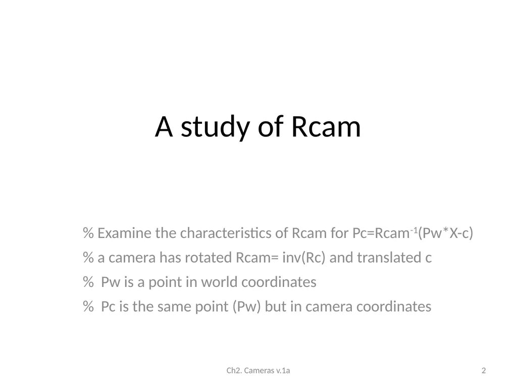
Rotation representation and usage KH Wong Ch2. Cameras v.1a 1 A study of Rcam Examine the characteristics of Rcam for PcRcam-1(PwX-c) a camera has rotated Rcam inv(Rc) and translated c Pw is a point in world coordinates Pc is the
Related Topics
Share
Embed code
Download this presentation From Below
"Rotation representation and usage KH Wong Ch2." is the property of its rightful owner. Permission is granted to download and print the materials on this website for personal, non-commercial use only, and to display it on your personal computer provided you do not modify the materials and that you retain all copyright notices contained in the materials. By downloading content from our website, you accept the terms of this agreement.
Presentation Transcript
01
Rotation representation and usage KH Wong Ch2. Cameras v.1a 1<br>
02
A study of Rcam % Examine the characteristics of Rcam for Pc=Rcam-1(Pw*X-c)
% a camera has rotated Rcam= inv(Rc) and translated c
% Pw is a point in world coordinates
% Pc is the same point (Pw) but in camera coordinates Ch2. Cameras v.1a 2<br>
% a camera has rotated Rcam= inv(Rc) and translated c
% Pw is a point in world coordinates
% Pc is the same point (Pw) but in camera coordinates Ch2. Cameras v.1a 2<br>
03
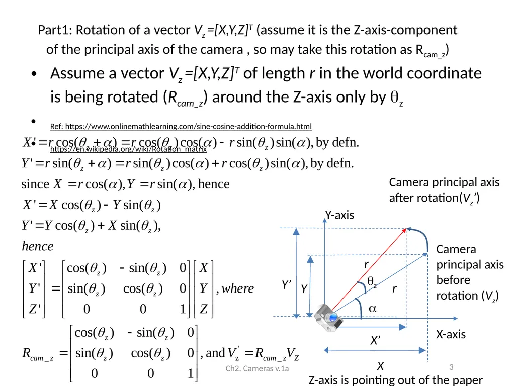
Part1: Rotation of a vector Vz =[X,Y,Z]T (assume it is the Z-axis-component of the principal axis of the camera , so may take this rotation as Rcam_z) Assume a vector Vz =[X,Y,Z]T of length r in the world coordinate is being rotated (Rcam_z) around the Z-axis only by z
Ref: https://www.onlinemathlearning.com/sine-cosine-addition-formula.html
https://en.wikipedia.org/wiki/Rotation_matrix Ch2. Cameras v.1a 3 X-axis z r r X’ X Y’ Y Y-axis Camera principal axis before rotation (Vz) Camera principal axis after rotation(Vz’) Z-axis is pointing out of the paper<br>
Ref: https://www.onlinemathlearning.com/sine-cosine-addition-formula.html
https://en.wikipedia.org/wiki/Rotation_matrix Ch2. Cameras v.1a 3 X-axis z r r X’ X Y’ Y Y-axis Camera principal axis before rotation (Vz) Camera principal axis after rotation(Vz’) Z-axis is pointing out of the paper<br>
04
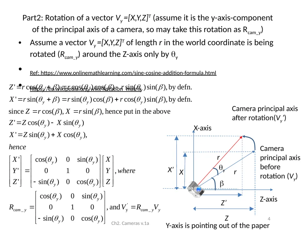
Part2: Rotation of a vector Vy =[X,Y,Z]T (assume it is the y-axis-component of the principal axis of a camera, so may take this rotation as Rcam_y) Assume a vector Vy =[X,Y,Z]T of length r in the world coordinate is being rotated (Rcam_y) around the Z-axis only by y
Ref: https://www.onlinemathlearning.com/sine-cosine-addition-formula.html
https://en.wikipedia.org/wiki/Rotation_matrix Ch2. Cameras v.1a 4 Z-axis y r r Z’ Z X’ X X-axis Camera principal axis before rotation (Vy) Camera principal axis after rotation(Vy’) Y-axis is pointing out of the paper<br>
Ref: https://www.onlinemathlearning.com/sine-cosine-addition-formula.html
https://en.wikipedia.org/wiki/Rotation_matrix Ch2. Cameras v.1a 4 Z-axis y r r Z’ Z X’ X X-axis Camera principal axis before rotation (Vy) Camera principal axis after rotation(Vy’) Y-axis is pointing out of the paper<br>
05
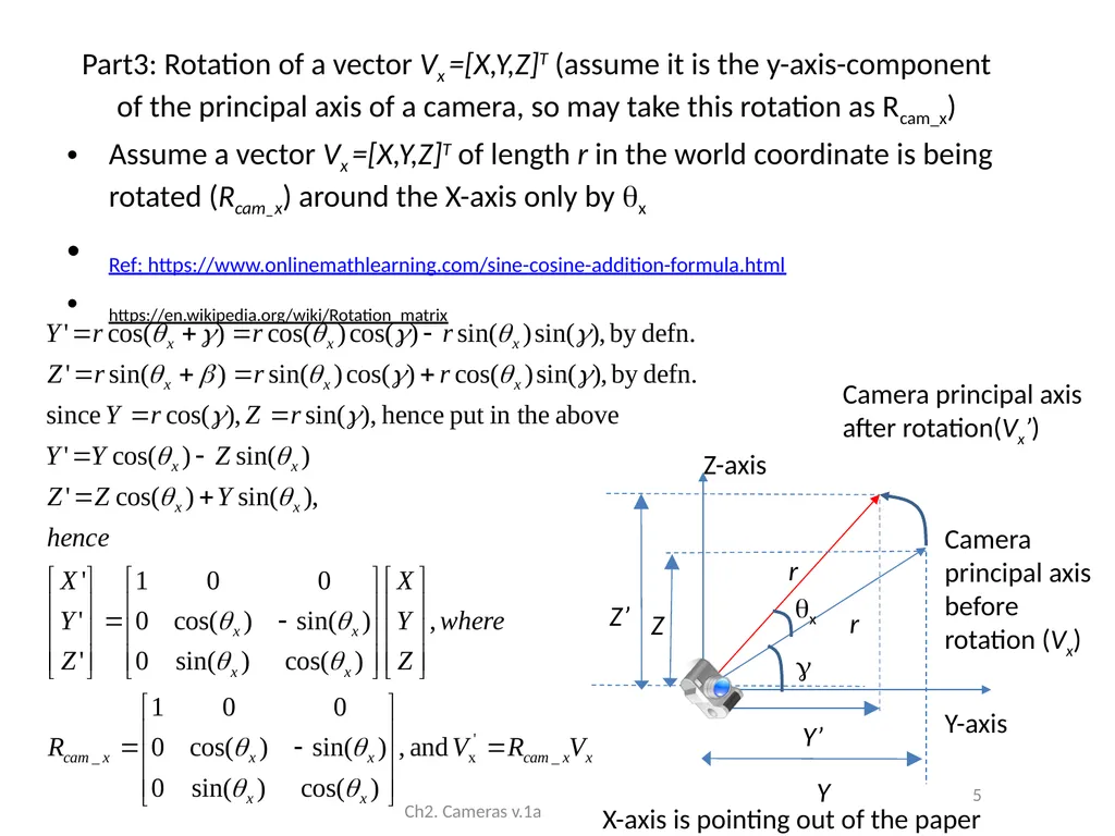
Part3: Rotation of a vector Vx =[X,Y,Z]T (assume it is the y-axis-component of the principal axis of a camera, so may take this rotation as Rcam_x) Assume a vector Vx =[X,Y,Z]T of length r in the world coordinate is being rotated (Rcam_x) around the X-axis only by x
Ref: https://www.onlinemathlearning.com/sine-cosine-addition-formula.html
https://en.wikipedia.org/wiki/Rotation_matrix Ch2. Cameras v.1a 5 Y-axis x r r Y’ Y Z’ Z Z-axis Camera principal axis before rotation (Vx) Camera principal axis after rotation(Vx’) X-axis is pointing out of the paper<br>
Ref: https://www.onlinemathlearning.com/sine-cosine-addition-formula.html
https://en.wikipedia.org/wiki/Rotation_matrix Ch2. Cameras v.1a 5 Y-axis x r r Y’ Y Z’ Z Z-axis Camera principal axis before rotation (Vx) Camera principal axis after rotation(Vx’) X-axis is pointing out of the paper<br>
06
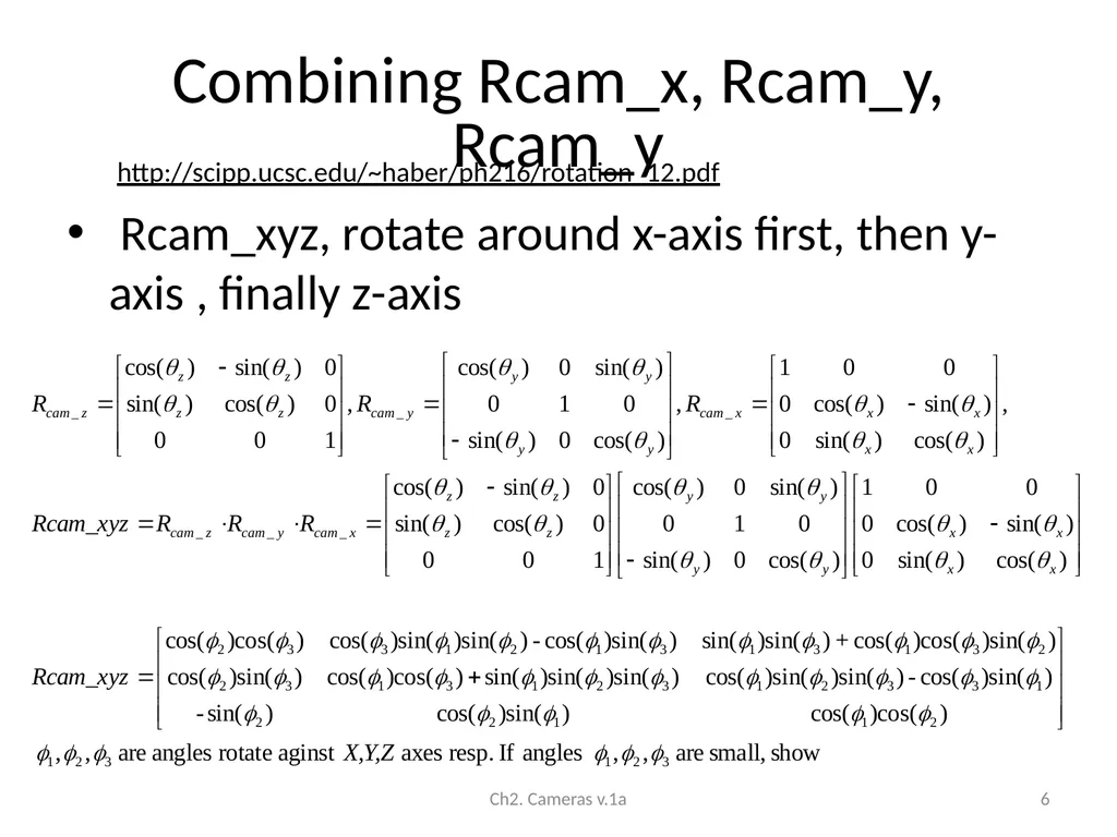
Combining Rcam_x, Rcam_y, Rcam_y Rcam_xyz, rotate around x-axis first, then y-axis , finally z-axis Ch2. Cameras v.1a 6 http://scipp.ucsc.edu/~haber/ph216/rotation_12.pdf<br>
07
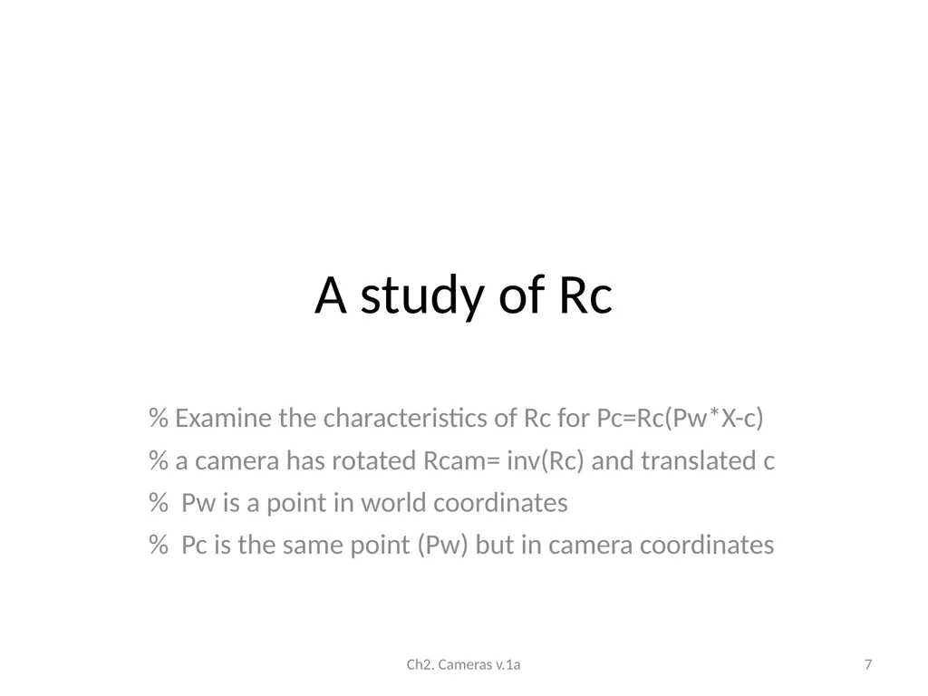
A study of Rc % Examine the characteristics of Rc for Pc=Rc(Pw*X-c)
% a camera has rotated Rcam= inv(Rc) and translated c
% Pw is a point in world coordinates
% Pc is the same point (Pw) but in camera coordinates Ch2. Cameras v.1a 7<br>
% a camera has rotated Rcam= inv(Rc) and translated c
% Pw is a point in world coordinates
% Pc is the same point (Pw) but in camera coordinates Ch2. Cameras v.1a 7<br>
08
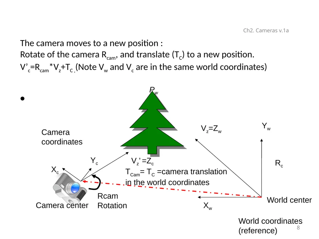
The camera moves to a new position :
Rotate of the camera Rcam, and translate (TC) to a new position. V’c=Rcam*Vz+TC ,(Note Vw and Vc are in the same world coordinates) Ch2. Cameras v.1a 8 Yw Xw Vz=Zw Vz’ =Zc Xc World coordinates
(reference) Camera
coordinates Yc Rcam
Rotation World center Rc Pw Camera center TCam= TC =camera translation
in the world coordinates<br>
(reference) Camera
coordinates Yc Rcam
Rotation World center Rc Pw Camera center TCam= TC =camera translation
in the world coordinates<br>
09
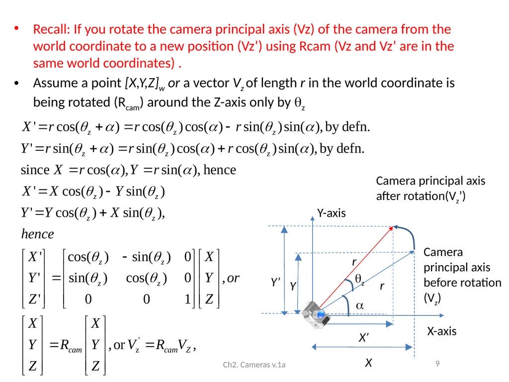
Recall: If you rotate the camera principal axis (Vz) of the camera from the world coordinate to a new position (Vz’) using Rcam (Vz and Vz’ are in the same world coordinates) .
Assume a point [X,Y,Z]w or a vector Vz of length r in the world coordinate is being rotated (Rcam) around the Z-axis only by z Ch2. Cameras v.1a 9 X-axis z r r X’ X Y’ Y Y-axis Camera principal axis before rotation (Vz) Camera principal axis after rotation(Vz’)<br>
Assume a point [X,Y,Z]w or a vector Vz of length r in the world coordinate is being rotated (Rcam) around the Z-axis only by z Ch2. Cameras v.1a 9 X-axis z r r X’ X Y’ Y Y-axis Camera principal axis before rotation (Vz) Camera principal axis after rotation(Vz’)<br>
10
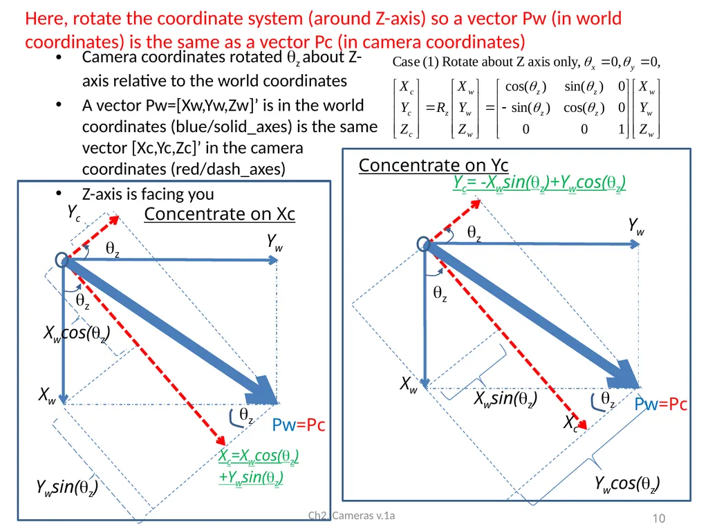
Camera coordinates rotated z about Z-axis relative to the world coordinates
A vector Pw=[Xw,Yw,Zw]’ is in the world coordinates (blue/solid_axes) is the same vector [Xc,Yc,Zc]’ in the camera coordinates (red/dash_axes)
Z-axis is facing you Ch2. Cameras v.1a z Xw Yw Yc z Pw=Pc Xc=Xwcos(z)+Ywsin(z) z Xwcos(z) Ywsin(z) z Xw Yw z Xc z Xwsin(z) Yc= -Xwsin(z)+Ywcos(z) Ywcos(z) Concentrate on Yc Concentrate on Xc 10 Here, rotate the coordinate system (around Z-axis) so a vector Pw (in world coordinates) is the same as a vector Pc (in camera coordinates) Pw=Pc<br>
A vector Pw=[Xw,Yw,Zw]’ is in the world coordinates (blue/solid_axes) is the same vector [Xc,Yc,Zc]’ in the camera coordinates (red/dash_axes)
Z-axis is facing you Ch2. Cameras v.1a z Xw Yw Yc z Pw=Pc Xc=Xwcos(z)+Ywsin(z) z Xwcos(z) Ywsin(z) z Xw Yw z Xc z Xwsin(z) Yc= -Xwsin(z)+Ywcos(z) Ywcos(z) Concentrate on Yc Concentrate on Xc 10 Here, rotate the coordinate system (around Z-axis) so a vector Pw (in world coordinates) is the same as a vector Pc (in camera coordinates) Pw=Pc<br>
11
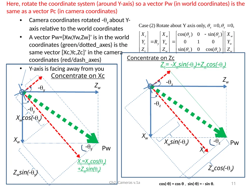
Camera coordinates rotated -y about Y-axis relative to the world coordinates
A vector Pw=[Xw,Yw,Zw]’ is in the world coordinates (green/dotted_axes) is the same vector [Xc,Yc,Zc]’ in the camera coordinates (red/dash_axes)
Y-axis is facing away from you Ch2. Cameras v.1a -y Xw Zw -y Pw Xc=Xwcos(y)+Zwsin(y) -y Xwcos(-y) Zwsin(-y) -z Xw Zw -z Pw Xc -z Xwsin(-z) Zc= -Xwsin(-z)+Zwcos(-z) Concentrate on Zc Concentrate on Xc 11 cos(-θ) = cos θ , sin(-θ) = - sin θ. Zwcos(-z) Here, rotate the coordinate system (around Y-axis) so a vector Pw (in world coordinates) is the same as a vector Pc (in camera coordinates)<br>
A vector Pw=[Xw,Yw,Zw]’ is in the world coordinates (green/dotted_axes) is the same vector [Xc,Yc,Zc]’ in the camera coordinates (red/dash_axes)
Y-axis is facing away from you Ch2. Cameras v.1a -y Xw Zw -y Pw Xc=Xwcos(y)+Zwsin(y) -y Xwcos(-y) Zwsin(-y) -z Xw Zw -z Pw Xc -z Xwsin(-z) Zc= -Xwsin(-z)+Zwcos(-z) Concentrate on Zc Concentrate on Xc 11 cos(-θ) = cos θ , sin(-θ) = - sin θ. Zwcos(-z) Here, rotate the coordinate system (around Y-axis) so a vector Pw (in world coordinates) is the same as a vector Pc (in camera coordinates)<br>
12
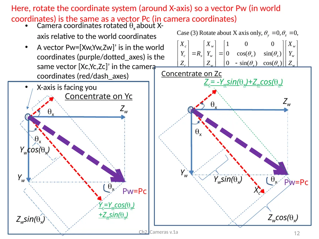
Camera coordinates rotated x about X-axis relative to the world coordinates
A vector Pw=[Xw,Yw,Zw]’ is in the world coordinates (purple/dotted_axes) is the same vector [Xc,Yc,Zc]’ in the camera coordinates (red/dash_axes)
X-axis is facing you Ch2. Cameras v.1a x Yw Zw x Yc=Ywcos(x)+Zwsin(x) x Ywcos(x) Zwsin(x) x Yw Zw x Xc x Ywsin(x) Zc= -Ywsin(x)+Zwcos(x) Zwcos(x) Concentrate on Zc Concentrate on Yc 12 Here, rotate the coordinate system (around X-axis) so a vector Pw (in world coordinates) is the same as a vector Pc (in camera coordinates) Pw=Pc Pw=Pc<br>
A vector Pw=[Xw,Yw,Zw]’ is in the world coordinates (purple/dotted_axes) is the same vector [Xc,Yc,Zc]’ in the camera coordinates (red/dash_axes)
X-axis is facing you Ch2. Cameras v.1a x Yw Zw x Yc=Ywcos(x)+Zwsin(x) x Ywcos(x) Zwsin(x) x Yw Zw x Xc x Ywsin(x) Zc= -Ywsin(x)+Zwcos(x) Zwcos(x) Concentrate on Zc Concentrate on Yc 12 Here, rotate the coordinate system (around X-axis) so a vector Pw (in world coordinates) is the same as a vector Pc (in camera coordinates) Pw=Pc Pw=Pc<br>
13
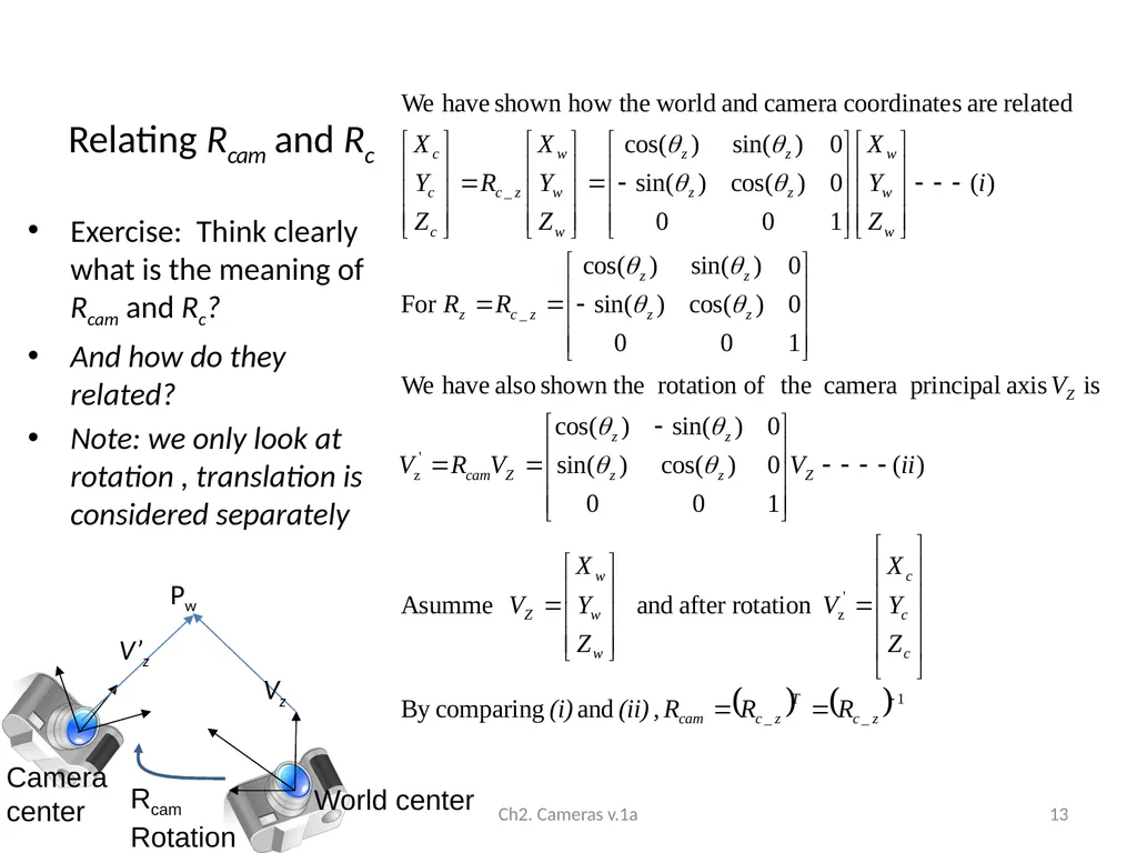
Relating Rcam and Rc Exercise: Think clearly what is the meaning of Rcam and Rc?
And how do they related?
Note: we only look at rotation , translation is considered separately Ch2. Cameras v.1a 13 World center Rcam
Rotation Camera center Pw Vz V’z<br>
And how do they related?
Note: we only look at rotation , translation is considered separately Ch2. Cameras v.1a 13 World center Rcam
Rotation Camera center Pw Vz V’z<br>
14
Precise definition of Rc, Tc and Rcam Rc: A vector Pw will appear as Pc in camera coordinates using Rc
Pc=Rc*Pw, where a vector Pw in world coordinates is the same vector Pc in camera coordinates . Pw does not change, it is only the coordinate system changes
Rcam is the rotational matrix that rotates the principal axis (Vz) of the camera position to a new position in the world coordinates. Rcam will change Vz, but it is always in the world coord. Sys. before and after the change.
Pc=Rc*Pw, where a vector Pw in world coordinates is the same vector Pc in camera coordinates
Rcam = (Rc) -1 (Note R-1=RT for rotation matrices)
Tcam=Tc is the translation of the camera center in the world coordinate system.
(-Tc) takes the camera center back to the world center in the world coordinate system. Ch2. Cameras v.1a 14<br>
Pc=Rc*Pw, where a vector Pw in world coordinates is the same vector Pc in camera coordinates . Pw does not change, it is only the coordinate system changes
Rcam is the rotational matrix that rotates the principal axis (Vz) of the camera position to a new position in the world coordinates. Rcam will change Vz, but it is always in the world coord. Sys. before and after the change.
Pc=Rc*Pw, where a vector Pw in world coordinates is the same vector Pc in camera coordinates
Rcam = (Rc) -1 (Note R-1=RT for rotation matrices)
Tcam=Tc is the translation of the camera center in the world coordinate system.
(-Tc) takes the camera center back to the world center in the world coordinate system. Ch2. Cameras v.1a 14<br>
15
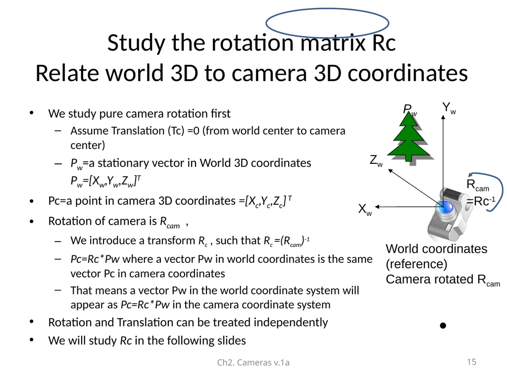
Study the rotation matrix Rc
Relate world 3D to camera 3D coordinates We study pure camera rotation first
Assume Translation (Tc) =0 (from world center to camera center)
Pw=a stationary vector in World 3D coordinates Pw=[Xw,Yw,Zw]T
Pc=a point in camera 3D coordinates =[Xc,Yc,Zc] T
Rotation of camera is Rcam ,
We introduce a transform Rc , such that Rc =(Rcam)-1
Pc=Rc*Pw where a vector Pw in world coordinates is the same vector Pc in camera coordinates
That means a vector Pw in the world coordinate system will appear as Pc=Rc*Pw in the camera coordinate system
Rotation and Translation can be treated independently
We will study Rc in the following slides Ch2. Cameras v.1a 15 Yw Xw Zw World coordinates
(reference)
Camera rotated Rcam Rcam
=Rc-1 Pw<br>
Assume Translation (Tc) =0 (from world center to camera center)
Pw=a stationary vector in World 3D coordinates Pw=[Xw,Yw,Zw]T
Pc=a point in camera 3D coordinates =[Xc,Yc,Zc] T
Rotation of camera is Rcam ,
We introduce a transform Rc , such that Rc =(Rcam)-1
Pc=Rc*Pw where a vector Pw in world coordinates is the same vector Pc in camera coordinates
That means a vector Pw in the world coordinate system will appear as Pc=Rc*Pw in the camera coordinate system
Rotation and Translation can be treated independently
We will study Rc in the following slides Ch2. Cameras v.1a 15 Yw Xw Zw World coordinates
(reference)
Camera rotated Rcam Rcam
=Rc-1 Pw<br>
16
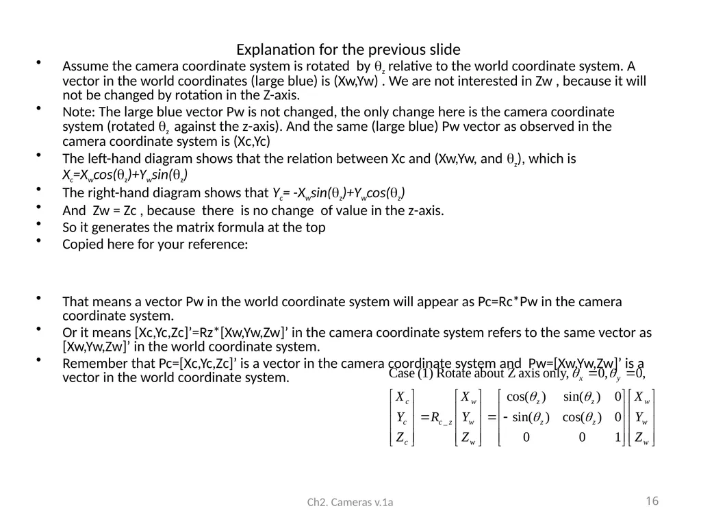
Explanation for the previous slide Assume the camera coordinate system is rotated by z relative to the world coordinate system. A vector in the world coordinates (large blue) is (Xw,Yw) . We are not interested in Zw , because it will not be changed by rotation in the Z-axis.
Note: The large blue vector Pw is not changed, the only change here is the camera coordinate system (rotated z against the z-axis). And the same (large blue) Pw vector as observed in the camera coordinate system is (Xc,Yc)
The left-hand diagram shows that the relation between Xc and (Xw,Yw, and z), which is Xc=Xwcos(z)+Ywsin(z)
The right-hand diagram shows that Yc= -Xwsin(z)+Ywcos(z)
And Zw = Zc , because there is no change of value in the z-axis.
So it generates the matrix formula at the top
Copied here for your reference:
That means a vector Pw in the world coordinate system will appear as Pc=Rc*Pw in the camera coordinate system.
Or it means [Xc,Yc,Zc]’=Rz*[Xw,Yw,Zw]’ in the camera coordinate system refers to the same vector as [Xw,Yw,Zw]’ in the world coordinate system.
Remember that Pc=[Xc,Yc,Zc]’ is a vector in the camera coordinate system and Pw=[Xw,Yw,Zw]’ is a vector in the world coordinate system. Ch2. Cameras v.1a 16<br>
Note: The large blue vector Pw is not changed, the only change here is the camera coordinate system (rotated z against the z-axis). And the same (large blue) Pw vector as observed in the camera coordinate system is (Xc,Yc)
The left-hand diagram shows that the relation between Xc and (Xw,Yw, and z), which is Xc=Xwcos(z)+Ywsin(z)
The right-hand diagram shows that Yc= -Xwsin(z)+Ywcos(z)
And Zw = Zc , because there is no change of value in the z-axis.
So it generates the matrix formula at the top
Copied here for your reference:
That means a vector Pw in the world coordinate system will appear as Pc=Rc*Pw in the camera coordinate system.
Or it means [Xc,Yc,Zc]’=Rz*[Xw,Yw,Zw]’ in the camera coordinate system refers to the same vector as [Xw,Yw,Zw]’ in the world coordinate system.
Remember that Pc=[Xc,Yc,Zc]’ is a vector in the camera coordinate system and Pw=[Xw,Yw,Zw]’ is a vector in the world coordinate system. Ch2. Cameras v.1a 16<br>
17
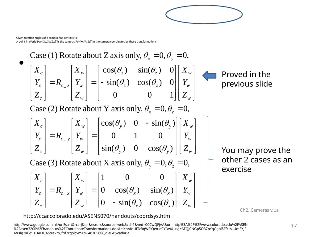
Given rotation angles of a camera find Rc=RxRyRz
A point in World Pw=[Xw,Yw,Zw]’ is the same as Pc=[Xc,Yc,Zc]’ in the camera coordinates by these transformations Ch2. Cameras v.1a 17 Proved in the previous slide
You may prove the other 2 cases as an exercise http://ccar.colorado.edu/ASEN5070/handouts/coordsys.htm http://www.google.com.hk/url?sa=t&rct=j&q=&esrc=s&source=web&cd=1&ved=0CCwQFjAA&url=http%3A%2F%2Fwww.colorado.edu%2FASEN%2Fasen3200%2Fhandouts%2FCoordinateTransformations.doc&ei=nAfdUfTzBqWSiQeo-oCYDw&usg=AFQjCNGp5O37pYqGghl5Fft1skUmSXJ2-A&sig2=6q91UADC3ZZreVm_frd7rg&bvm=bv.48705608,d.aGc&cad=rja<br>
You may prove the other 2 cases as an exercise http://ccar.colorado.edu/ASEN5070/handouts/coordsys.htm http://www.google.com.hk/url?sa=t&rct=j&q=&esrc=s&source=web&cd=1&ved=0CCwQFjAA&url=http%3A%2F%2Fwww.colorado.edu%2FASEN%2Fasen3200%2Fhandouts%2FCoordinateTransformations.doc&ei=nAfdUfTzBqWSiQeo-oCYDw&usg=AFQjCNGp5O37pYqGghl5Fft1skUmSXJ2-A&sig2=6q91UADC3ZZreVm_frd7rg&bvm=bv.48705608,d.aGc&cad=rja<br>
18
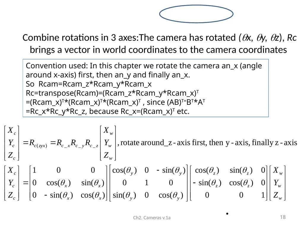
Combine rotations in 3 axes:The camera has rotated (x, y, z), Rc brings a vector in world coordinates to the camera coordinates Ch2. Cameras v.1a 18 Convention used: In this chapter we rotate the camera an_x (angle around x-axis) first, then an_y and finally an_x.
So Rcam=Rcam_z*Rcam_y*Rcam_x
Rc=transpose(Rcam)=(Rcam_z*Rcam_y*Rcam_x)T
=(Rcam_x)T*(Rcam_x)T*(Rcam_x)T , since (AB)T=BT*AT
=Rc_x*Rc_y*Rc_z, because Rc_x=(Rcam_x)T etc.<br>
So Rcam=Rcam_z*Rcam_y*Rcam_x
Rc=transpose(Rcam)=(Rcam_z*Rcam_y*Rcam_x)T
=(Rcam_x)T*(Rcam_x)T*(Rcam_x)T , since (AB)T=BT*AT
=Rc_x*Rc_y*Rc_z, because Rc_x=(Rcam_x)T etc.<br>
19
Matlab program for Rc
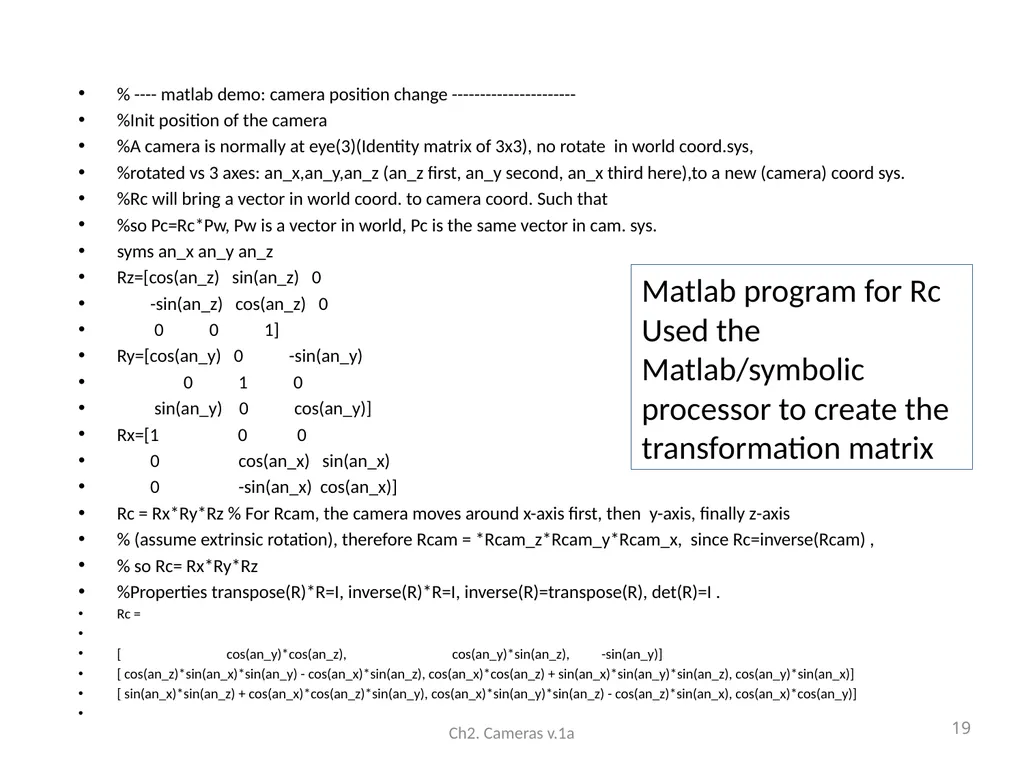
Used the Matlab/symbolic processor to create the transformation matrix % ---- matlab demo: camera position change ----------------------
%Init position of the camera
%A camera is normally at eye(3)(Identity matrix of 3x3), no rotate in world coord.sys,
%rotated vs 3 axes: an_x,an_y,an_z (an_z first, an_y second, an_x third here),to a new (camera) coord sys.
%Rc will bring a vector in world coord. to camera coord. Such that
%so Pc=Rc*Pw, Pw is a vector in world, Pc is the same vector in cam. sys.
syms an_x an_y an_z
Rz=[cos(an_z) sin(an_z) 0
-sin(an_z) cos(an_z) 0
0 0 1]
Ry=[cos(an_y) 0 -sin(an_y)
0 1 0
sin(an_y) 0 cos(an_y)]
Rx=[1 0 0
0 cos(an_x) sin(an_x)
0 -sin(an_x) cos(an_x)]
Rc = Rx*Ry*Rz % For Rcam, the camera moves around x-axis first, then y-axis, finally z-axis
% (assume extrinsic rotation), therefore Rcam = *Rcam_z*Rcam_y*Rcam_x, since Rc=inverse(Rcam) ,
% so Rc= Rx*Ry*Rz
%Properties transpose(R)*R=I, inverse(R)*R=I, inverse(R)=transpose(R), det(R)=I .
Rc =
[ cos(an_y)*cos(an_z), cos(an_y)*sin(an_z), -sin(an_y)]
[ cos(an_z)*sin(an_x)*sin(an_y) - cos(an_x)*sin(an_z), cos(an_x)*cos(an_z) + sin(an_x)*sin(an_y)*sin(an_z), cos(an_y)*sin(an_x)]
[ sin(an_x)*sin(an_z) + cos(an_x)*cos(an_z)*sin(an_y), cos(an_x)*sin(an_y)*sin(an_z) - cos(an_z)*sin(an_x), cos(an_x)*cos(an_y)] Ch2. Cameras v.1a 19<br>
%Init position of the camera
%A camera is normally at eye(3)(Identity matrix of 3x3), no rotate in world coord.sys,
%rotated vs 3 axes: an_x,an_y,an_z (an_z first, an_y second, an_x third here),to a new (camera) coord sys.
%Rc will bring a vector in world coord. to camera coord. Such that
%so Pc=Rc*Pw, Pw is a vector in world, Pc is the same vector in cam. sys.
syms an_x an_y an_z
Rz=[cos(an_z) sin(an_z) 0
-sin(an_z) cos(an_z) 0
0 0 1]
Ry=[cos(an_y) 0 -sin(an_y)
0 1 0
sin(an_y) 0 cos(an_y)]
Rx=[1 0 0
0 cos(an_x) sin(an_x)
0 -sin(an_x) cos(an_x)]
Rc = Rx*Ry*Rz % For Rcam, the camera moves around x-axis first, then y-axis, finally z-axis
% (assume extrinsic rotation), therefore Rcam = *Rcam_z*Rcam_y*Rcam_x, since Rc=inverse(Rcam) ,
% so Rc= Rx*Ry*Rz
%Properties transpose(R)*R=I, inverse(R)*R=I, inverse(R)=transpose(R), det(R)=I .
Rc =
[ cos(an_y)*cos(an_z), cos(an_y)*sin(an_z), -sin(an_y)]
[ cos(an_z)*sin(an_x)*sin(an_y) - cos(an_x)*sin(an_z), cos(an_x)*cos(an_z) + sin(an_x)*sin(an_y)*sin(an_z), cos(an_y)*sin(an_x)]
[ sin(an_x)*sin(an_z) + cos(an_x)*cos(an_z)*sin(an_y), cos(an_x)*sin(an_y)*sin(an_z) - cos(an_z)*sin(an_x), cos(an_x)*cos(an_y)] Ch2. Cameras v.1a 19<br>
20
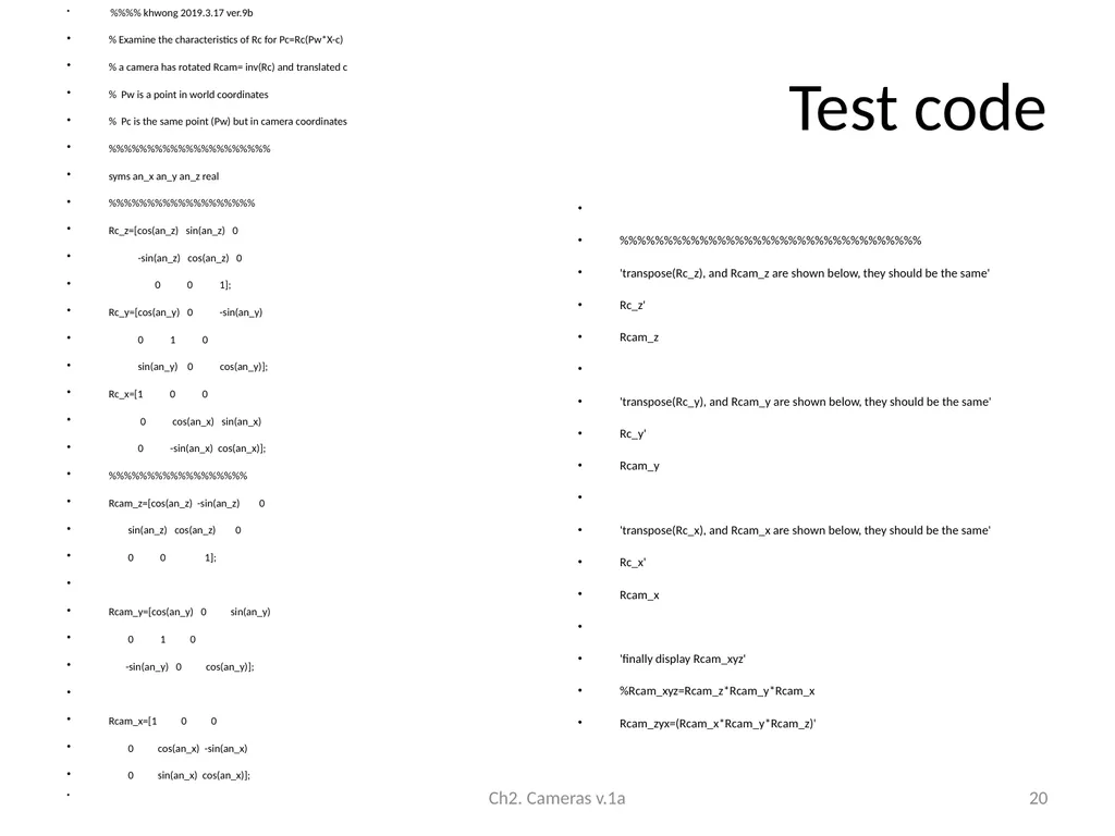
Test code %%%% khwong 2019.3.17 ver.9b
% Examine the characteristics of Rc for Pc=Rc(Pw*X-c)
% a camera has rotated Rcam= inv(Rc) and translated c
% Pw is a point in world coordinates
% Pc is the same point (Pw) but in camera coordinates
%%%%%%%%%%%%%%%%%%%%%
syms an_x an_y an_z real
%%%%%%%%%%%%%%%%%%%
Rc_z=[cos(an_z) sin(an_z) 0
-sin(an_z) cos(an_z) 0
0 0 1];
Rc_y=[cos(an_y) 0 -sin(an_y)
0 1 0
sin(an_y) 0 cos(an_y)];
Rc_x=[1 0 0
0 cos(an_x) sin(an_x)
0 -sin(an_x) cos(an_x)];
%%%%%%%%%%%%%%%%%%
Rcam_z=[cos(an_z) -sin(an_z) 0
sin(an_z) cos(an_z) 0
0 0 1];
Rcam_y=[cos(an_y) 0 sin(an_y)
0 1 0
-sin(an_y) 0 cos(an_y)];
Rcam_x=[1 0 0
0 cos(an_x) -sin(an_x)
0 sin(an_x) cos(an_x)]; %%%%%%%%%%%%%%%%%%%%%%%%%%%%%%%%%%
'transpose(Rc_z), and Rcam_z are shown below, they should be the same'
Rc_z'
Rcam_z
'transpose(Rc_y), and Rcam_y are shown below, they should be the same'
Rc_y'
Rcam_y
'transpose(Rc_x), and Rcam_x are shown below, they should be the same'
Rc_x'
Rcam_x
'finally display Rcam_xyz'
%Rcam_xyz=Rcam_z*Rcam_y*Rcam_x
Rcam_zyx=(Rcam_x*Rcam_y*Rcam_z)' Ch2. Cameras v.1a 20<br>
% Examine the characteristics of Rc for Pc=Rc(Pw*X-c)
% a camera has rotated Rcam= inv(Rc) and translated c
% Pw is a point in world coordinates
% Pc is the same point (Pw) but in camera coordinates
%%%%%%%%%%%%%%%%%%%%%
syms an_x an_y an_z real
%%%%%%%%%%%%%%%%%%%
Rc_z=[cos(an_z) sin(an_z) 0
-sin(an_z) cos(an_z) 0
0 0 1];
Rc_y=[cos(an_y) 0 -sin(an_y)
0 1 0
sin(an_y) 0 cos(an_y)];
Rc_x=[1 0 0
0 cos(an_x) sin(an_x)
0 -sin(an_x) cos(an_x)];
%%%%%%%%%%%%%%%%%%
Rcam_z=[cos(an_z) -sin(an_z) 0
sin(an_z) cos(an_z) 0
0 0 1];
Rcam_y=[cos(an_y) 0 sin(an_y)
0 1 0
-sin(an_y) 0 cos(an_y)];
Rcam_x=[1 0 0
0 cos(an_x) -sin(an_x)
0 sin(an_x) cos(an_x)]; %%%%%%%%%%%%%%%%%%%%%%%%%%%%%%%%%%
'transpose(Rc_z), and Rcam_z are shown below, they should be the same'
Rc_z'
Rcam_z
'transpose(Rc_y), and Rcam_y are shown below, they should be the same'
Rc_y'
Rcam_y
'transpose(Rc_x), and Rcam_x are shown below, they should be the same'
Rc_x'
Rcam_x
'finally display Rcam_xyz'
%Rcam_xyz=Rcam_z*Rcam_y*Rcam_x
Rcam_zyx=(Rcam_x*Rcam_y*Rcam_z)' Ch2. Cameras v.1a 20<br>
21
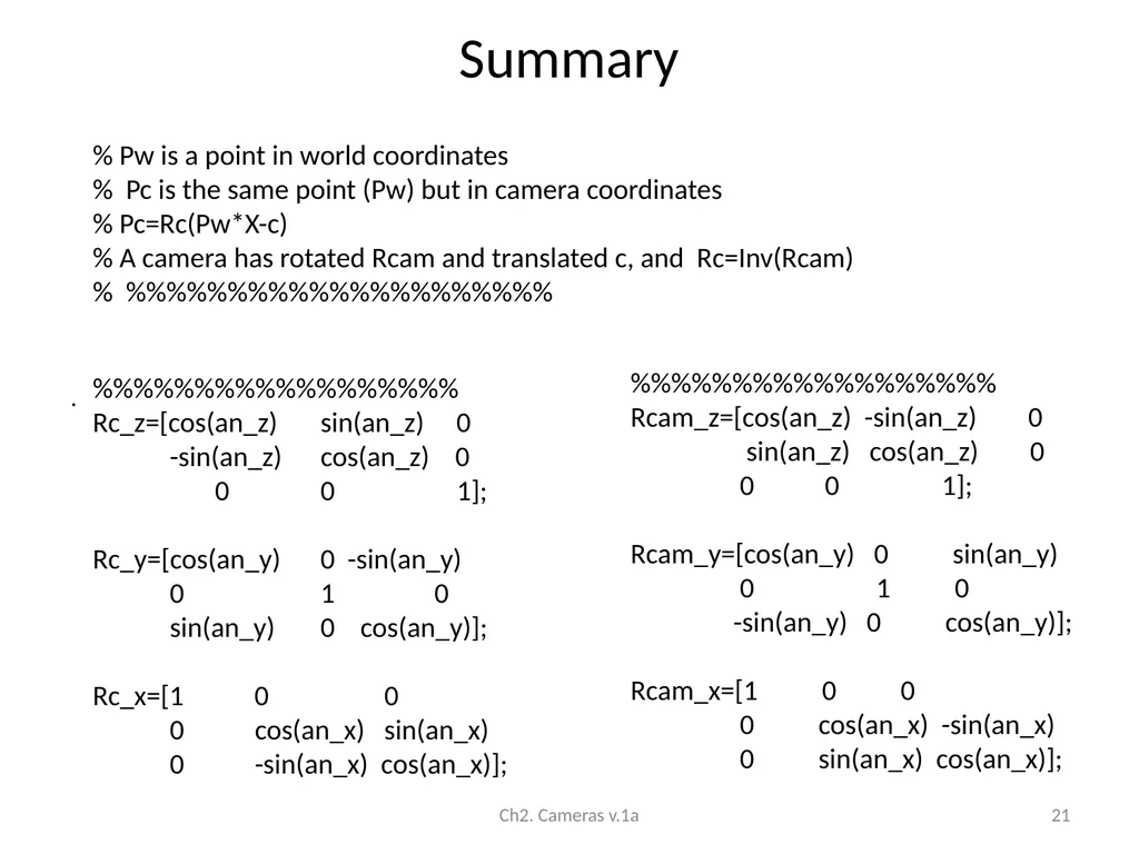
Summary Ch2. Cameras v.1a 21 %%%%%%%%%%%%%%%%%%
Rc_z=[cos(an_z) sin(an_z) 0
-sin(an_z) cos(an_z) 0
0 0 1];
Rc_y=[cos(an_y) 0 -sin(an_y)
0 1 0
sin(an_y) 0 cos(an_y)];
Rc_x=[1 0 0
0 cos(an_x) sin(an_x)
0 -sin(an_x) cos(an_x)]; %%%%%%%%%%%%%%%%%%
Rcam_z=[cos(an_z) -sin(an_z) 0
sin(an_z) cos(an_z) 0
0 0 1];
Rcam_y=[cos(an_y) 0 sin(an_y)
0 1 0
-sin(an_y) 0 cos(an_y)];
Rcam_x=[1 0 0
0 cos(an_x) -sin(an_x)
0 sin(an_x) cos(an_x)]; % Pw is a point in world coordinates
% Pc is the same point (Pw) but in camera coordinates
% Pc=Rc(Pw*X-c)
% A camera has rotated Rcam and translated c, and Rc=Inv(Rcam)
% %%%%%%%%%%%%%%%%%%%%%<br>
Rc_z=[cos(an_z) sin(an_z) 0
-sin(an_z) cos(an_z) 0
0 0 1];
Rc_y=[cos(an_y) 0 -sin(an_y)
0 1 0
sin(an_y) 0 cos(an_y)];
Rc_x=[1 0 0
0 cos(an_x) sin(an_x)
0 -sin(an_x) cos(an_x)]; %%%%%%%%%%%%%%%%%%
Rcam_z=[cos(an_z) -sin(an_z) 0
sin(an_z) cos(an_z) 0
0 0 1];
Rcam_y=[cos(an_y) 0 sin(an_y)
0 1 0
-sin(an_y) 0 cos(an_y)];
Rcam_x=[1 0 0
0 cos(an_x) -sin(an_x)
0 sin(an_x) cos(an_x)]; % Pw is a point in world coordinates
% Pc is the same point (Pw) but in camera coordinates
% Pc=Rc(Pw*X-c)
% A camera has rotated Rcam and translated c, and Rc=Inv(Rcam)
% %%%%%%%%%%%%%%%%%%%%%<br>
22
Introduction meaning
Representation
Euler angles and Tait–Bryan angles
Axis angles
quaternions Ch2. Cameras v.1a 22<br>
Representation
Euler angles and Tait–Bryan angles
Axis angles
quaternions Ch2. Cameras v.1a 22<br>
23
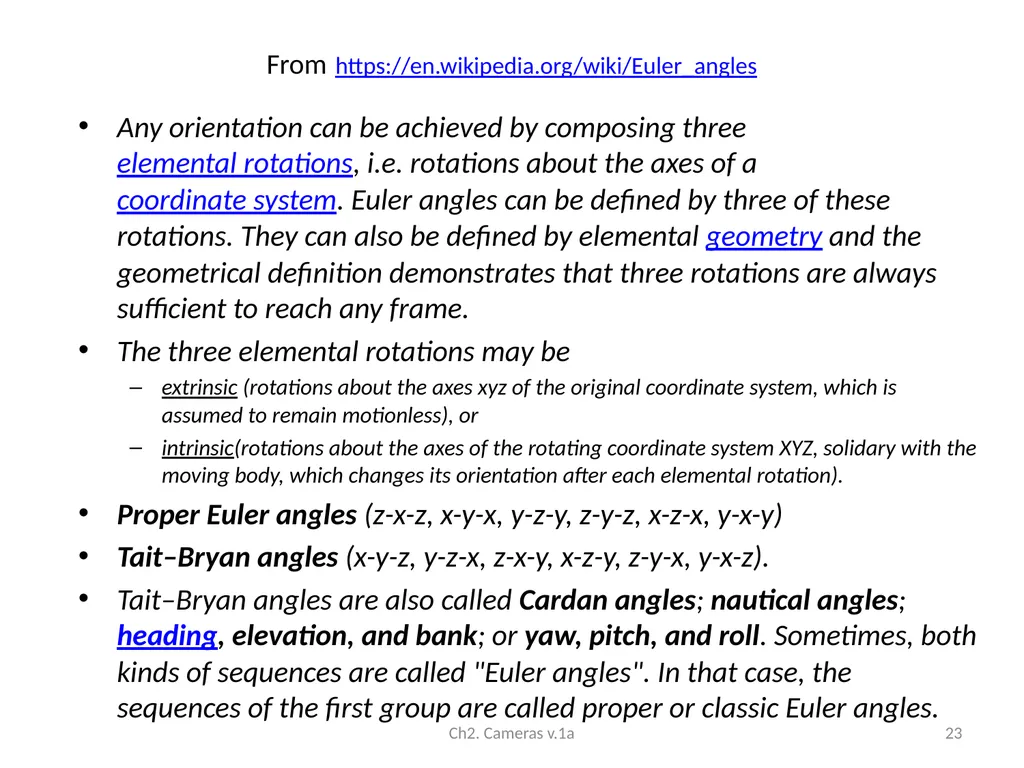
From https://en.wikipedia.org/wiki/Euler_angles Any orientation can be achieved by composing three elemental rotations, i.e. rotations about the axes of a coordinate system. Euler angles can be defined by three of these rotations. They can also be defined by elemental geometry and the geometrical definition demonstrates that three rotations are always sufficient to reach any frame.
The three elemental rotations may be
extrinsic (rotations about the axes xyz of the original coordinate system, which is assumed to remain motionless), or
intrinsic(rotations about the axes of the rotating coordinate system XYZ, solidary with the moving body, which changes its orientation after each elemental rotation).
Proper Euler angles (z-x-z, x-y-x, y-z-y, z-y-z, x-z-x, y-x-y)
Tait–Bryan angles (x-y-z, y-z-x, z-x-y, x-z-y, z-y-x, y-x-z).
Tait–Bryan angles are also called Cardan angles; nautical angles; heading, elevation, and bank; or yaw, pitch, and roll. Sometimes, both kinds of sequences are called "Euler angles". In that case, the sequences of the first group are called proper or classic Euler angles. Ch2. Cameras v.1a 23<br>
The three elemental rotations may be
extrinsic (rotations about the axes xyz of the original coordinate system, which is assumed to remain motionless), or
intrinsic(rotations about the axes of the rotating coordinate system XYZ, solidary with the moving body, which changes its orientation after each elemental rotation).
Proper Euler angles (z-x-z, x-y-x, y-z-y, z-y-z, x-z-x, y-x-y)
Tait–Bryan angles (x-y-z, y-z-x, z-x-y, x-z-y, z-y-x, y-x-z).
Tait–Bryan angles are also called Cardan angles; nautical angles; heading, elevation, and bank; or yaw, pitch, and roll. Sometimes, both kinds of sequences are called "Euler angles". In that case, the sequences of the first group are called proper or classic Euler angles. Ch2. Cameras v.1a 23<br>
24
Tait–Bryan angles v.s. Proper Euler angles
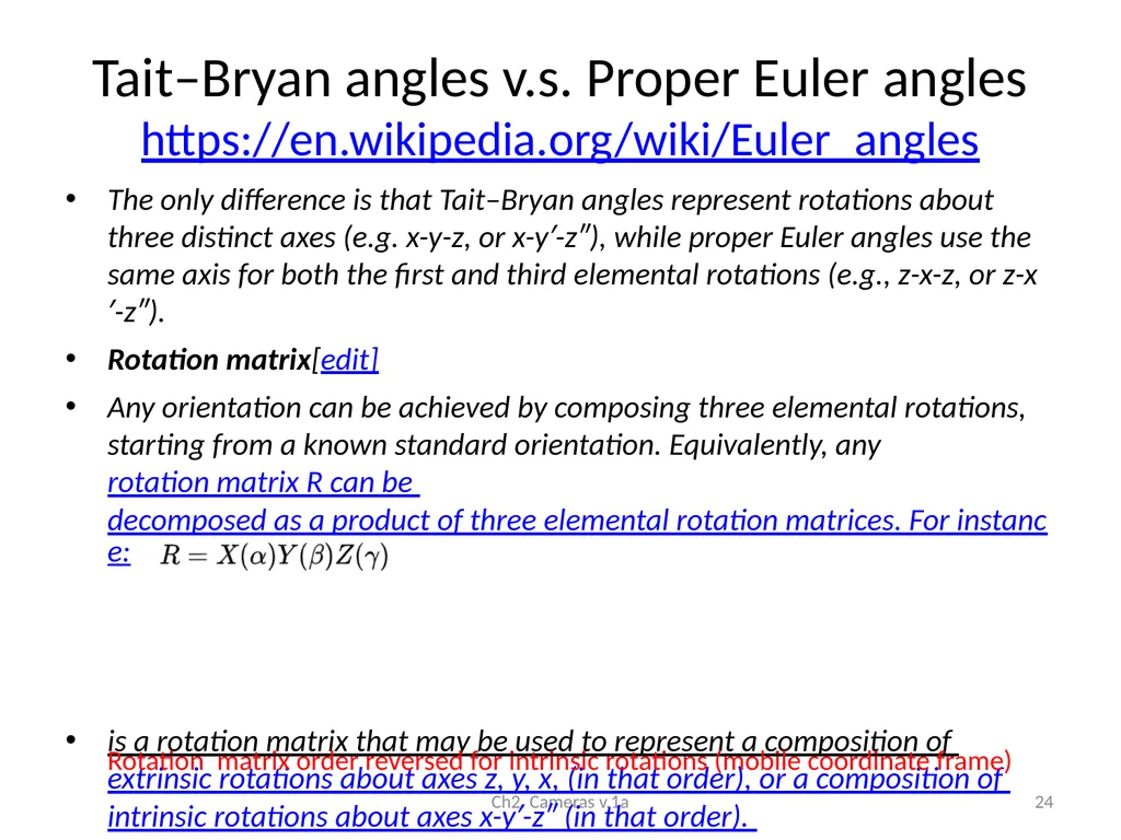
https://en.wikipedia.org/wiki/Euler_angles The only difference is that Tait–Bryan angles represent rotations about three distinct axes (e.g. x-y-z, or x-y′-z″), while proper Euler angles use the same axis for both the first and third elemental rotations (e.g., z-x-z, or z-x′-z″).
Rotation matrix[edit]
Any orientation can be achieved by composing three elemental rotations, starting from a known standard orientation. Equivalently, any rotation matrix R can be decomposed as a product of three elemental rotation matrices. For instance:
is a rotation matrix that may be used to represent a composition of extrinsic rotations about axes z, y, x, (in that order), or a composition of intrinsic rotations about axes x-y′-z″ (in that order). Ch2. Cameras v.1a 24 Rotation matrix order reversed for intrinsic rotations (mobile coordinate frame)<br>
Rotation matrix[edit]
Any orientation can be achieved by composing three elemental rotations, starting from a known standard orientation. Equivalently, any rotation matrix R can be decomposed as a product of three elemental rotation matrices. For instance:
is a rotation matrix that may be used to represent a composition of extrinsic rotations about axes z, y, x, (in that order), or a composition of intrinsic rotations about axes x-y′-z″ (in that order). Ch2. Cameras v.1a 24 Rotation matrix order reversed for intrinsic rotations (mobile coordinate frame)<br>
25
See the demo
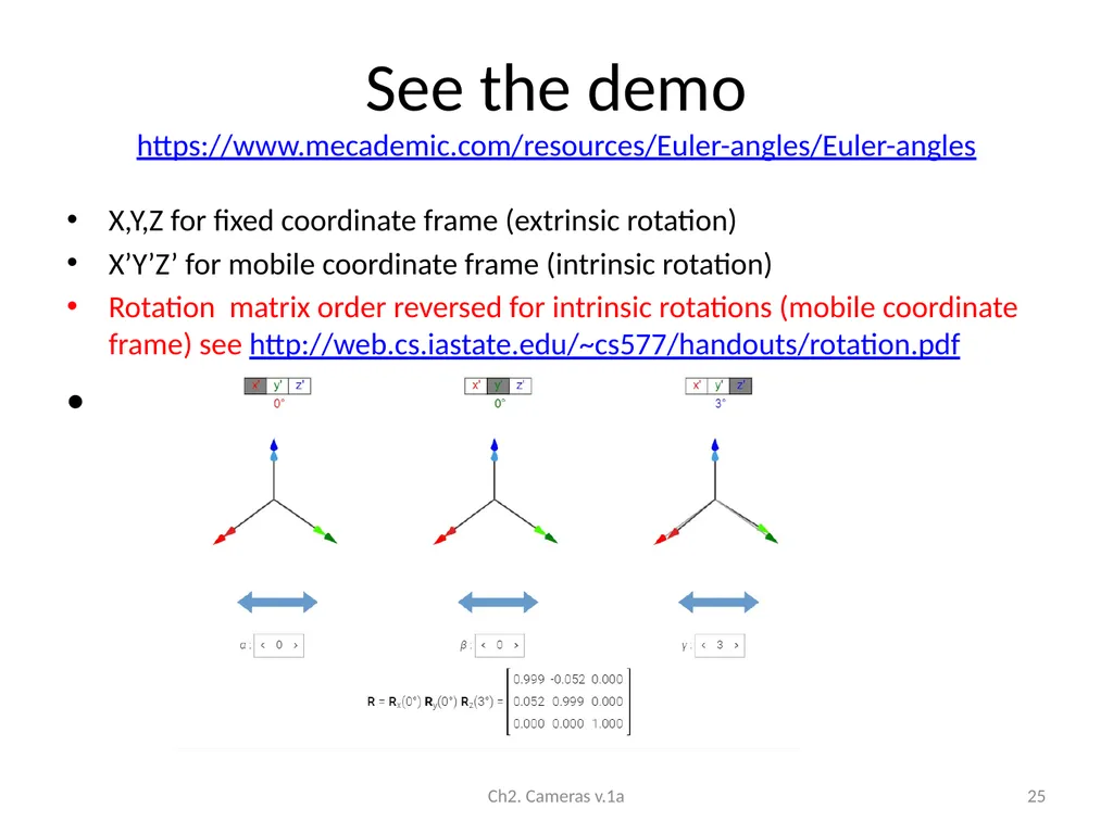
https://www.mecademic.com/resources/Euler-angles/Euler-angles X,Y,Z for fixed coordinate frame (extrinsic rotation)
X’Y’Z’ for mobile coordinate frame (intrinsic rotation)
Rotation matrix order reversed for intrinsic rotations (mobile coordinate frame) see http://web.cs.iastate.edu/~cs577/handouts/rotation.pdf Ch2. Cameras v.1a 25<br>
X’Y’Z’ for mobile coordinate frame (intrinsic rotation)
Rotation matrix order reversed for intrinsic rotations (mobile coordinate frame) see http://web.cs.iastate.edu/~cs577/handouts/rotation.pdf Ch2. Cameras v.1a 25<br>
26
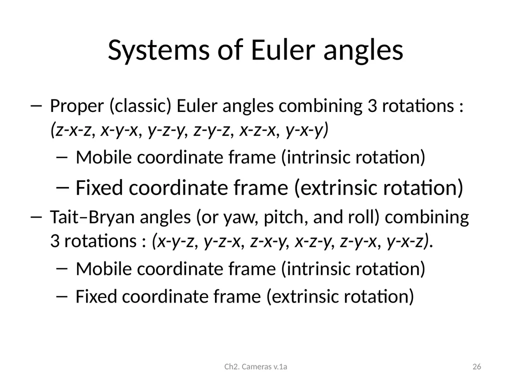
Systems of Euler angles Proper (classic) Euler angles combining 3 rotations : (z-x-z, x-y-x, y-z-y, z-y-z, x-z-x, y-x-y)
Mobile coordinate frame (intrinsic rotation)
Fixed coordinate frame (extrinsic rotation)
Tait–Bryan angles (or yaw, pitch, and roll) combining 3 rotations : (x-y-z, y-z-x, z-x-y, x-z-y, z-y-x, y-x-z).
Mobile coordinate frame (intrinsic rotation)
Fixed coordinate frame (extrinsic rotation) Ch2. Cameras v.1a 26<br>
Mobile coordinate frame (intrinsic rotation)
Fixed coordinate frame (extrinsic rotation)
Tait–Bryan angles (or yaw, pitch, and roll) combining 3 rotations : (x-y-z, y-z-x, z-x-y, x-z-y, z-y-x, y-x-z).
Mobile coordinate frame (intrinsic rotation)
Fixed coordinate frame (extrinsic rotation) Ch2. Cameras v.1a 26<br>
27
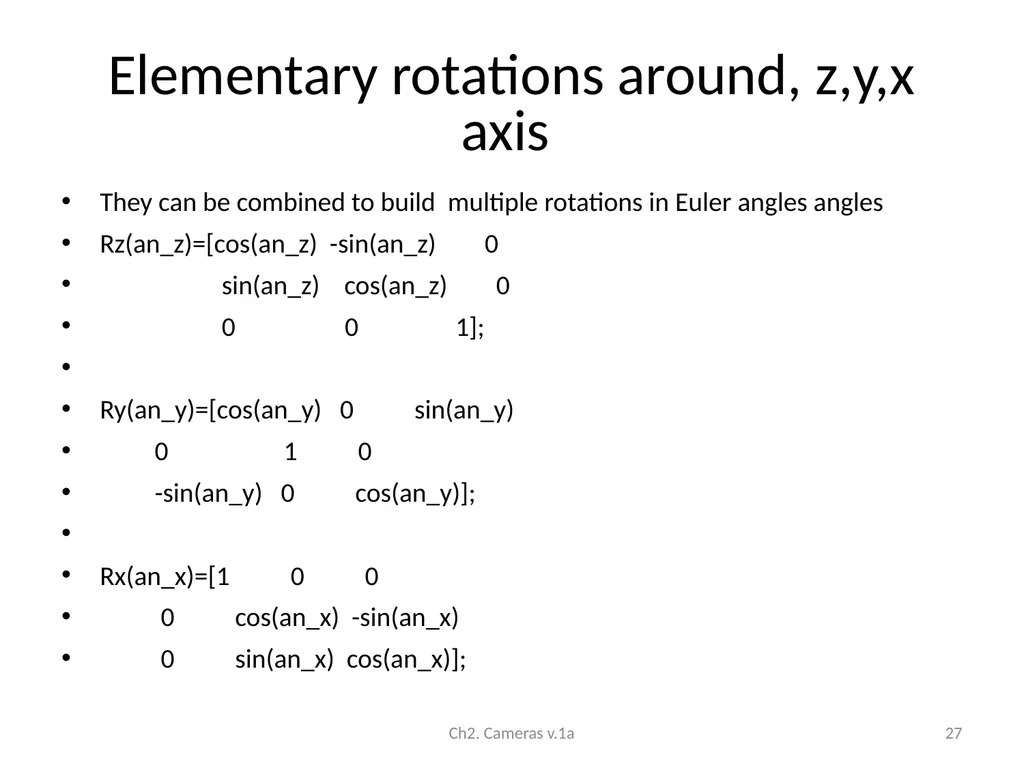
Elementary rotations around, z,y,x axis They can be combined to build multiple rotations in Euler angles angles
Rz(an_z)=[cos(an_z) -sin(an_z) 0
sin(an_z) cos(an_z) 0
0 0 1];
Ry(an_y)=[cos(an_y) 0 sin(an_y)
0 1 0
-sin(an_y) 0 cos(an_y)];
Rx(an_x)=[1 0 0
0 cos(an_x) -sin(an_x)
0 sin(an_x) cos(an_x)]; Ch2. Cameras v.1a 27<br>
Rz(an_z)=[cos(an_z) -sin(an_z) 0
sin(an_z) cos(an_z) 0
0 0 1];
Ry(an_y)=[cos(an_y) 0 sin(an_y)
0 1 0
-sin(an_y) 0 cos(an_y)];
Rx(an_x)=[1 0 0
0 cos(an_x) -sin(an_x)
0 sin(an_x) cos(an_x)]; Ch2. Cameras v.1a 27<br>
28
Proper Euler angles
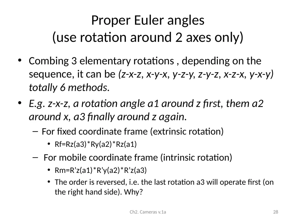
(use rotation around 2 axes only) Combing 3 elementary rotations , depending on the sequence, it can be (z-x-z, x-y-x, y-z-y, z-y-z, x-z-x, y-x-y) totally 6 methods.
E.g. z-x-z, a rotation angle a1 around z first, them a2 around x, a3 finally around z again.
For fixed coordinate frame (extrinsic rotation)
Rf=Rz(a3)*Ry(a2)*Rz(a1)
For mobile coordinate frame (intrinsic rotation)
Rm=R’z(a1)*R’y(a2)*R’z(a3)
The order is reversed, i.e. the last rotation a3 will operate first (on the right hand side). Why? Ch2. Cameras v.1a 28<br>
E.g. z-x-z, a rotation angle a1 around z first, them a2 around x, a3 finally around z again.
For fixed coordinate frame (extrinsic rotation)
Rf=Rz(a3)*Ry(a2)*Rz(a1)
For mobile coordinate frame (intrinsic rotation)
Rm=R’z(a1)*R’y(a2)*R’z(a3)
The order is reversed, i.e. the last rotation a3 will operate first (on the right hand side). Why? Ch2. Cameras v.1a 28<br>
29
Tait–Bryan angles (yaw, pitch, roll)
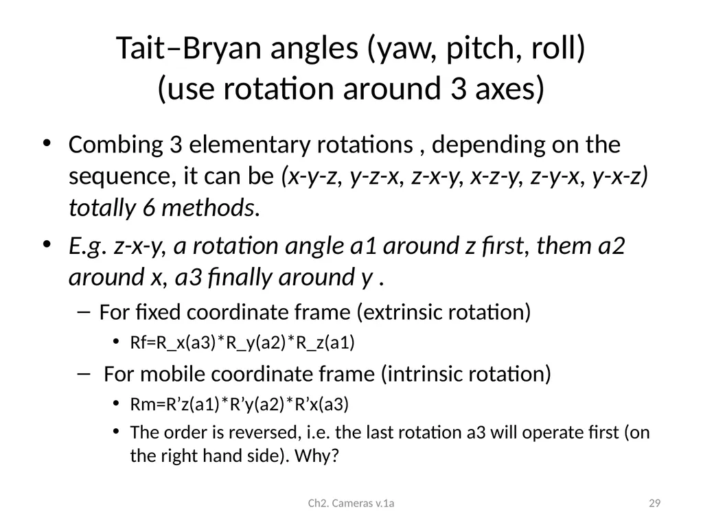
(use rotation around 3 axes) Combing 3 elementary rotations , depending on the sequence, it can be (x-y-z, y-z-x, z-x-y, x-z-y, z-y-x, y-x-z) totally 6 methods.
E.g. z-x-y, a rotation angle a1 around z first, them a2 around x, a3 finally around y .
For fixed coordinate frame (extrinsic rotation)
Rf=R_x(a3)*R_y(a2)*R_z(a1)
For mobile coordinate frame (intrinsic rotation)
Rm=R’z(a1)*R’y(a2)*R’x(a3)
The order is reversed, i.e. the last rotation a3 will operate first (on the right hand side). Why? Ch2. Cameras v.1a 29<br>
E.g. z-x-y, a rotation angle a1 around z first, them a2 around x, a3 finally around y .
For fixed coordinate frame (extrinsic rotation)
Rf=R_x(a3)*R_y(a2)*R_z(a1)
For mobile coordinate frame (intrinsic rotation)
Rm=R’z(a1)*R’y(a2)*R’x(a3)
The order is reversed, i.e. the last rotation a3 will operate first (on the right hand side). Why? Ch2. Cameras v.1a 29<br>
30
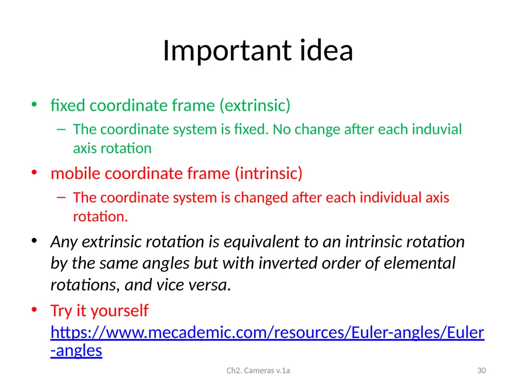
Important idea fixed coordinate frame (extrinsic)
The coordinate system is fixed. No change after each induvial axis rotation
mobile coordinate frame (intrinsic)
The coordinate system is changed after each individual axis rotation.
Any extrinsic rotation is equivalent to an intrinsic rotation by the same angles but with inverted order of elemental rotations, and vice versa.
Try it yourself https://www.mecademic.com/resources/Euler-angles/Euler-angles Ch2. Cameras v.1a 30<br>
The coordinate system is fixed. No change after each induvial axis rotation
mobile coordinate frame (intrinsic)
The coordinate system is changed after each individual axis rotation.
Any extrinsic rotation is equivalent to an intrinsic rotation by the same angles but with inverted order of elemental rotations, and vice versa.
Try it yourself https://www.mecademic.com/resources/Euler-angles/Euler-angles Ch2. Cameras v.1a 30<br>
31
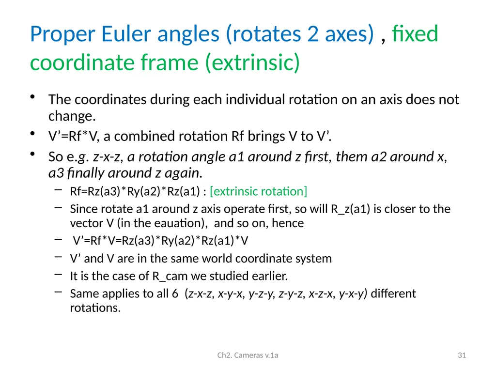
Proper Euler angles (rotates 2 axes) , fixed coordinate frame (extrinsic) The coordinates during each individual rotation on an axis does not change.
V’=Rf*V, a combined rotation Rf brings V to V’.
So e.g. z-x-z, a rotation angle a1 around z first, them a2 around x, a3 finally around z again.
Rf=Rz(a3)*Ry(a2)*Rz(a1) : [extrinsic rotation]
Since rotate a1 around z axis operate first, so will R_z(a1) is closer to the vector V (in the eauation), and so on, hence
V’=Rf*V=Rz(a3)*Ry(a2)*Rz(a1)*V
V’ and V are in the same world coordinate system
It is the case of R_cam we studied earlier.
Same applies to all 6 (z-x-z, x-y-x, y-z-y, z-y-z, x-z-x, y-x-y) different rotations. Ch2. Cameras v.1a 31<br>
V’=Rf*V, a combined rotation Rf brings V to V’.
So e.g. z-x-z, a rotation angle a1 around z first, them a2 around x, a3 finally around z again.
Rf=Rz(a3)*Ry(a2)*Rz(a1) : [extrinsic rotation]
Since rotate a1 around z axis operate first, so will R_z(a1) is closer to the vector V (in the eauation), and so on, hence
V’=Rf*V=Rz(a3)*Ry(a2)*Rz(a1)*V
V’ and V are in the same world coordinate system
It is the case of R_cam we studied earlier.
Same applies to all 6 (z-x-z, x-y-x, y-z-y, z-y-z, x-z-x, y-x-y) different rotations. Ch2. Cameras v.1a 31<br>
32
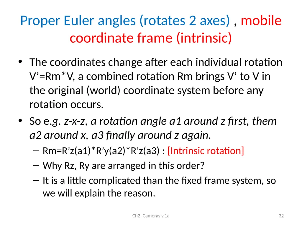
Proper Euler angles (rotates 2 axes) , mobile coordinate frame (intrinsic) The coordinates change after each individual rotation V’=Rm*V, a combined rotation Rm brings V’ to V in the original (world) coordinate system before any rotation occurs.
So e.g. z-x-z, a rotation angle a1 around z first, them a2 around x, a3 finally around z again.
Rm=R’z(a1)*R’y(a2)*R’z(a3) : [Intrinsic rotation]
Why Rz, Ry are arranged in this order?
It is a little complicated than the fixed frame system, so we will explain the reason. Ch2. Cameras v.1a 32<br>
So e.g. z-x-z, a rotation angle a1 around z first, them a2 around x, a3 finally around z again.
Rm=R’z(a1)*R’y(a2)*R’z(a3) : [Intrinsic rotation]
Why Rz, Ry are arranged in this order?
It is a little complicated than the fixed frame system, so we will explain the reason. Ch2. Cameras v.1a 32<br>
33
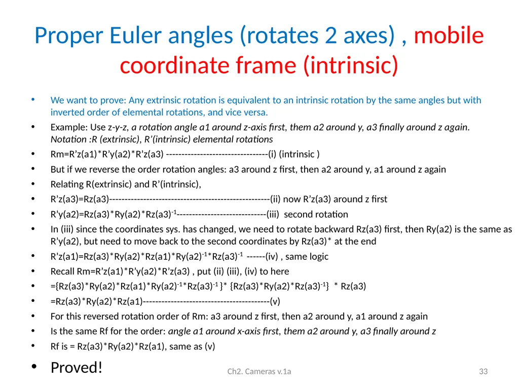
Proper Euler angles (rotates 2 axes) , mobile coordinate frame (intrinsic) We want to prove: Any extrinsic rotation is equivalent to an intrinsic rotation by the same angles but with inverted order of elemental rotations, and vice versa.
Example: Use z-y-z, a rotation angle a1 around z-axis first, them a2 around y, a3 finally around z again. Notation :R (extrinsic), R’(intrinsic) elemental rotations
Rm=R’z(a1)*R’y(a2)*R’z(a3) ---------------------------------(i) (intrinsic )
But if we reverse the order rotation angles: a3 around z first, then a2 around y, a1 around z again
Relating R(extrinsic) and R’(intrinsic),
R’z(a3)=Rz(a3)----------------------------------------------------(ii) now R’z(a3) around z first
R’y(a2)=Rz(a3)*Ry(a2)*Rz(a3)-1-----------------------------(iii) second rotation
In (iii) since the coordinates sys. has changed, we need to rotate backward Rz(a3) first, then Ry(a2) is the same as R’y(a2), but need to move back to the second coordinates by Rz(a3)* at the end
R’z(a1)=Rz(a3)*Ry(a2)*Rz(a1)*Ry(a2)-1*Rz(a3)-1 ------(iv) , same logic
Recall Rm=R’z(a1)*R’y(a2)*R’z(a3) , put (ii) (iii), (iv) to here
={Rz(a3)*Ry(a2)*Rz(a1)*Ry(a2)-1*Rz(a3)-1 }* {Rz(a3)*Ry(a2)*Rz(a3)-1} * Rz(a3)
=Rz(a3)*Ry(a2)*Rz(a1)-----------------------------------------(v)
For this reversed rotation order of Rm: a3 around z first, then a2 around y, a1 around z again
Is the same Rf for the order: angle a1 around x-axis first, them a2 around y, a3 finally around z
Rf is = Rz(a3)*Ry(a2)*Rz(a1), same as (v)
Proved! Ch2. Cameras v.1a 33<br>
Example: Use z-y-z, a rotation angle a1 around z-axis first, them a2 around y, a3 finally around z again. Notation :R (extrinsic), R’(intrinsic) elemental rotations
Rm=R’z(a1)*R’y(a2)*R’z(a3) ---------------------------------(i) (intrinsic )
But if we reverse the order rotation angles: a3 around z first, then a2 around y, a1 around z again
Relating R(extrinsic) and R’(intrinsic),
R’z(a3)=Rz(a3)----------------------------------------------------(ii) now R’z(a3) around z first
R’y(a2)=Rz(a3)*Ry(a2)*Rz(a3)-1-----------------------------(iii) second rotation
In (iii) since the coordinates sys. has changed, we need to rotate backward Rz(a3) first, then Ry(a2) is the same as R’y(a2), but need to move back to the second coordinates by Rz(a3)* at the end
R’z(a1)=Rz(a3)*Ry(a2)*Rz(a1)*Ry(a2)-1*Rz(a3)-1 ------(iv) , same logic
Recall Rm=R’z(a1)*R’y(a2)*R’z(a3) , put (ii) (iii), (iv) to here
={Rz(a3)*Ry(a2)*Rz(a1)*Ry(a2)-1*Rz(a3)-1 }* {Rz(a3)*Ry(a2)*Rz(a3)-1} * Rz(a3)
=Rz(a3)*Ry(a2)*Rz(a1)-----------------------------------------(v)
For this reversed rotation order of Rm: a3 around z first, then a2 around y, a1 around z again
Is the same Rf for the order: angle a1 around x-axis first, them a2 around y, a3 finally around z
Rf is = Rz(a3)*Ry(a2)*Rz(a1), same as (v)
Proved! Ch2. Cameras v.1a 33<br>
34
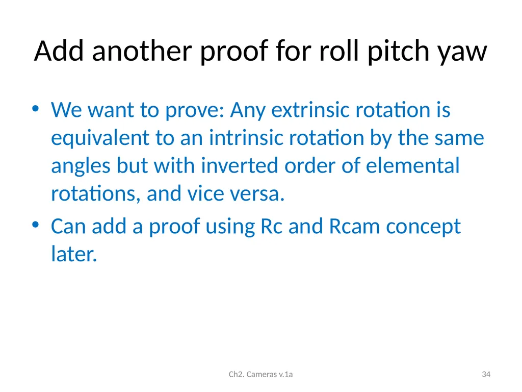
Add another proof for roll pitch yaw We want to prove: Any extrinsic rotation is equivalent to an intrinsic rotation by the same angles but with inverted order of elemental rotations, and vice versa.
Can add a proof using Rc and Rcam concept later. Ch2. Cameras v.1a 34<br>
Can add a proof using Rc and Rcam concept later. Ch2. Cameras v.1a 34<br>
35
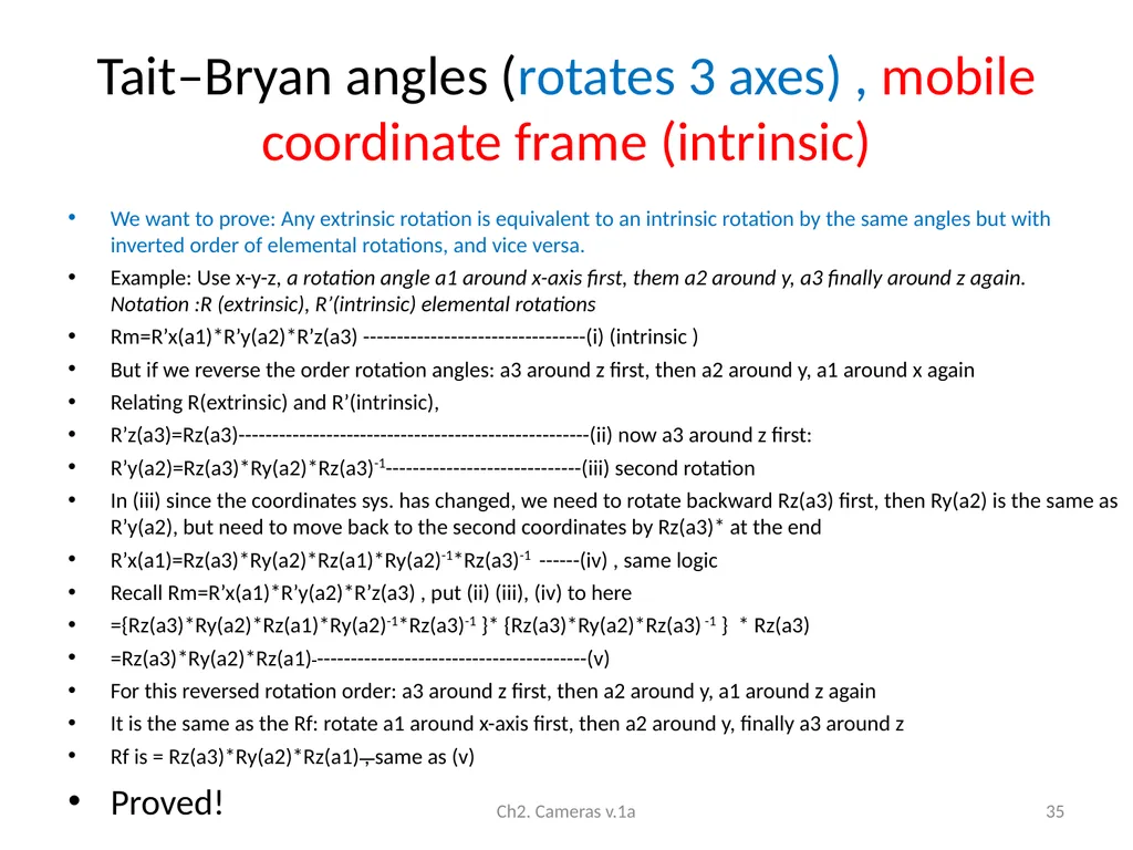
Tait–Bryan angles (rotates 3 axes) , mobile coordinate frame (intrinsic) We want to prove: Any extrinsic rotation is equivalent to an intrinsic rotation by the same angles but with inverted order of elemental rotations, and vice versa.
Example: Use x-y-z, a rotation angle a1 around x-axis first, them a2 around y, a3 finally around z again. Notation :R (extrinsic), R’(intrinsic) elemental rotations
Rm=R’x(a1)*R’y(a2)*R’z(a3) ---------------------------------(i) (intrinsic )
But if we reverse the order rotation angles: a3 around z first, then a2 around y, a1 around x again
Relating R(extrinsic) and R’(intrinsic),
R’z(a3)=Rz(a3)----------------------------------------------------(ii) now a3 around z first:
R’y(a2)=Rz(a3)*Ry(a2)*Rz(a3)-1-----------------------------(iii) second rotation
In (iii) since the coordinates sys. has changed, we need to rotate backward Rz(a3) first, then Ry(a2) is the same as R’y(a2), but need to move back to the second coordinates by Rz(a3)* at the end
R’x(a1)=Rz(a3)*Ry(a2)*Rz(a1)*Ry(a2)-1*Rz(a3)-1 ------(iv) , same logic
Recall Rm=R’x(a1)*R’y(a2)*R’z(a3) , put (ii) (iii), (iv) to here
={Rz(a3)*Ry(a2)*Rz(a1)*Ry(a2)-1*Rz(a3)-1 }* {Rz(a3)*Ry(a2)*Rz(a3) -1 } * Rz(a3)
=Rz(a3)*Ry(a2)*Rz(a1) ----------------------------------------(v)
For this reversed rotation order: a3 around z first, then a2 around y, a1 around z again
It is the same as the Rf: rotate a1 around x-axis first, then a2 around y, finally a3 around z
Rf is = Rz(a3)*Ry(a2)*Rz(a1) , same as (v)
Proved! Ch2. Cameras v.1a 35<br>
Example: Use x-y-z, a rotation angle a1 around x-axis first, them a2 around y, a3 finally around z again. Notation :R (extrinsic), R’(intrinsic) elemental rotations
Rm=R’x(a1)*R’y(a2)*R’z(a3) ---------------------------------(i) (intrinsic )
But if we reverse the order rotation angles: a3 around z first, then a2 around y, a1 around x again
Relating R(extrinsic) and R’(intrinsic),
R’z(a3)=Rz(a3)----------------------------------------------------(ii) now a3 around z first:
R’y(a2)=Rz(a3)*Ry(a2)*Rz(a3)-1-----------------------------(iii) second rotation
In (iii) since the coordinates sys. has changed, we need to rotate backward Rz(a3) first, then Ry(a2) is the same as R’y(a2), but need to move back to the second coordinates by Rz(a3)* at the end
R’x(a1)=Rz(a3)*Ry(a2)*Rz(a1)*Ry(a2)-1*Rz(a3)-1 ------(iv) , same logic
Recall Rm=R’x(a1)*R’y(a2)*R’z(a3) , put (ii) (iii), (iv) to here
={Rz(a3)*Ry(a2)*Rz(a1)*Ry(a2)-1*Rz(a3)-1 }* {Rz(a3)*Ry(a2)*Rz(a3) -1 } * Rz(a3)
=Rz(a3)*Ry(a2)*Rz(a1) ----------------------------------------(v)
For this reversed rotation order: a3 around z first, then a2 around y, a1 around z again
It is the same as the Rf: rotate a1 around x-axis first, then a2 around y, finally a3 around z
Rf is = Rz(a3)*Ry(a2)*Rz(a1) , same as (v)
Proved! Ch2. Cameras v.1a 35<br>
36
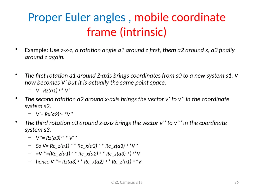
Proper Euler angles , mobile coordinate frame (intrinsic) Example: Use z-x-z, a rotation angle a1 around z first, them a2 around x, a3 finally around z again.
The first rotation a1 around Z-axis brings coordinates from s0 to a new system s1, V now becomes V’ but it is actually the same point space.
V= Rz(a1)-1 * V’
The second rotation a2 around x-axis brings the vector v’ to v’’ in the coordinate system s2.
V’= Rx(a2) -1 *V’’
The third rotation a3 around z-axis brings the vector v’’ to v’’’ in the coordinate system s3.
V’’= Rz(a3) -1 * V’’’
So V= Rc_z(a1) -1 * Rc_x(a2) -1 * Rc_z(a3) -1 *V’’’
=V’’’=(Rc_z(a1) -1 * Rc_x(a2) -1 * Rc_z(a3) -1 )-1*V
hence V’’’= Rz(a3)-1 * Rc_x(a2) -1 * Rc_z(a1) -1 *V Ch2. Cameras v.1a 36<br>
The first rotation a1 around Z-axis brings coordinates from s0 to a new system s1, V now becomes V’ but it is actually the same point space.
V= Rz(a1)-1 * V’
The second rotation a2 around x-axis brings the vector v’ to v’’ in the coordinate system s2.
V’= Rx(a2) -1 *V’’
The third rotation a3 around z-axis brings the vector v’’ to v’’’ in the coordinate system s3.
V’’= Rz(a3) -1 * V’’’
So V= Rc_z(a1) -1 * Rc_x(a2) -1 * Rc_z(a3) -1 *V’’’
=V’’’=(Rc_z(a1) -1 * Rc_x(a2) -1 * Rc_z(a3) -1 )-1*V
hence V’’’= Rz(a3)-1 * Rc_x(a2) -1 * Rc_z(a1) -1 *V Ch2. Cameras v.1a 36<br>
37
Quaternions Quaternions Ch2. Cameras v.1a 37<br>
38
Axis-angle
(Rodrigues rotation formula) Axis-angle requires 4 parameters
Compact representation using a 3x1 vector (i.e. In rvecs of opencv camera calibration and solve pnp)
Refernces: https://en.wikipedia.org/wiki/Axis%E2%80%93angle_representation
https://en.wikipedia.org/wiki/Rodrigues%27_rotation_formula Ch2. Cameras v.1a 38<br>
Compact representation using a 3x1 vector (i.e. In rvecs of opencv camera calibration and solve pnp)
Refernces: https://en.wikipedia.org/wiki/Axis%E2%80%93angle_representation
https://en.wikipedia.org/wiki/Rodrigues%27_rotation_formula Ch2. Cameras v.1a 38<br>
39
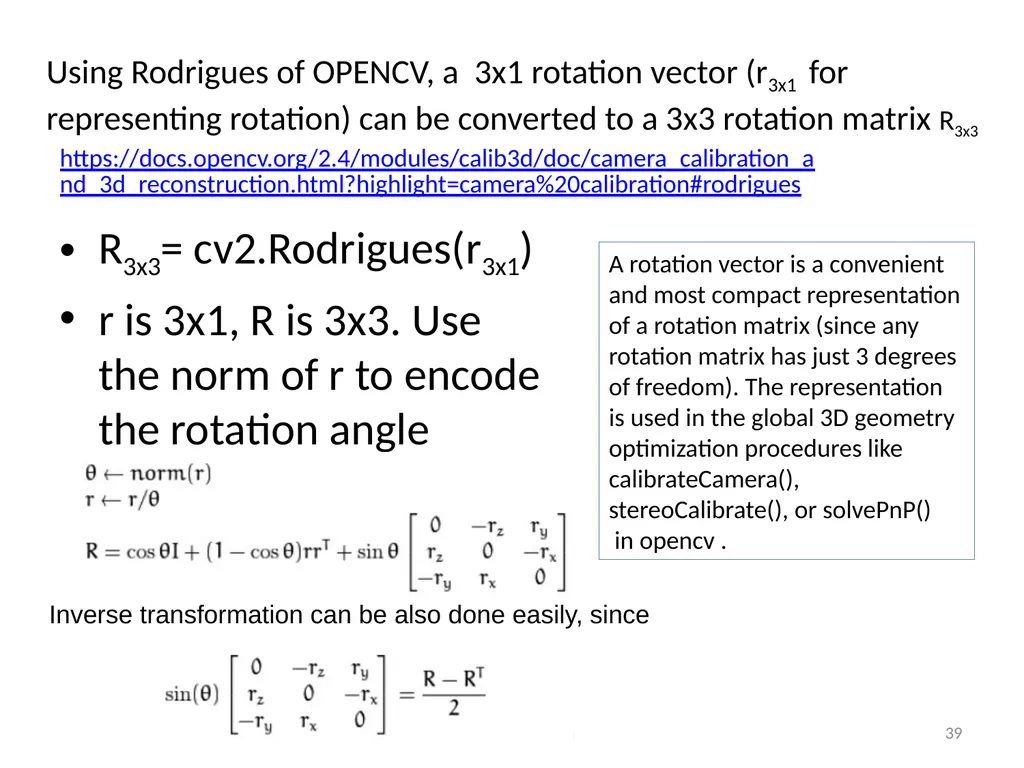
Using Rodrigues of OPENCV, a 3x1 rotation vector (r3x1 for representing rotation) can be converted to a 3x3 rotation matrix R3x3 R3x3= cv2.Rodrigues(r3x1)
r is 3x1, R is 3x3. Use the norm of r to encode the rotation angle Ch2. Cameras v.1a 39 https://docs.opencv.org/2.4/modules/calib3d/doc/camera_calibration_and_3d_reconstruction.html?highlight=camera%20calibration#rodrigues Inverse transformation can be also done easily, since A rotation vector is a convenient and most compact representation of a rotation matrix (since any rotation matrix has just 3 degrees of freedom). The representation is used in the global 3D geometry optimization procedures like calibrateCamera(), stereoCalibrate(), or solvePnP()
in opencv .<br>
r is 3x1, R is 3x3. Use the norm of r to encode the rotation angle Ch2. Cameras v.1a 39 https://docs.opencv.org/2.4/modules/calib3d/doc/camera_calibration_and_3d_reconstruction.html?highlight=camera%20calibration#rodrigues Inverse transformation can be also done easily, since A rotation vector is a convenient and most compact representation of a rotation matrix (since any rotation matrix has just 3 degrees of freedom). The representation is used in the global 3D geometry optimization procedures like calibrateCamera(), stereoCalibrate(), or solvePnP()
in opencv .<br>
40
Gimbal lock A gimbal is a ring that is suspended so it can rotate about an axis.
When angles of 2 axes are the same it is a problem and is called the Gimbal lock problem
See
https://www.youtube.com/watch?v=oj7v3MXJL3M
https://www.youtube.com/watch?v=zc8b2Jo7mno Ch2. Cameras v.1a 40<br>
When angles of 2 axes are the same it is a problem and is called the Gimbal lock problem
See
https://www.youtube.com/watch?v=oj7v3MXJL3M
https://www.youtube.com/watch?v=zc8b2Jo7mno Ch2. Cameras v.1a 40<br>
41
References https://en.wikipedia.org/wiki/Euler_angles
How is orientation in space represented with Euler angles? https://www.mecademic.com/resources/Euler-angles/Euler-angles
A Tutorial on Euler Angles and Quaternions http://www.weizmann.ac.il/sci-tea/benari/sites/sci-tea.benari/files/uploads/softwareAndLearningMaterials/quaternion-tutorial-2-0-1.pdf
https://en.wikipedia.org/wiki/Davenport_chained_rotations Ch2. Cameras v.1a 41<br>
How is orientation in space represented with Euler angles? https://www.mecademic.com/resources/Euler-angles/Euler-angles
A Tutorial on Euler Angles and Quaternions http://www.weizmann.ac.il/sci-tea/benari/sites/sci-tea.benari/files/uploads/softwareAndLearningMaterials/quaternion-tutorial-2-0-1.pdf
https://en.wikipedia.org/wiki/Davenport_chained_rotations Ch2. Cameras v.1a 41<br>