
SANJIVANI K. B. P. POLYTECHNIC, KOPARGAON With NBA



Description: SANJIVANI K. B. P. POLYTECHNIC, KOPARGAON With NBA ACCREDIATED programs , Approved by AICTE, New Delhi, Recognized by Govt. of Maharashtra, Affiliated to Maharashtra State Board of Technical Education, Mumbai, ISO 9001:2015 Certified
Related Topics
Download Presentation
"SANJIVANI K. B. P. POLYTECHNIC, KOPARGAON With NBA" is the property of its rightful owner. Permission is granted to download and print the materials on this website for personal, non-commercial use only, and to display it on your personal computer provided you do not modify the materials and that you retain all copyright notices contained in the materials. By downloading content from our website, you accept the terms of this agreement.
Presentation Transcript
slide1. SANJIVANI K. B. P. POLYTECHNIC, KOPARGAON
With NBA ACCREDIATED programs , Approved by AICTE, New Delhi,
Recognized by Govt. of Maharashtra, Affiliated to Maharashtra State Board of Technical Education, Mumbai, ISO 9001:2015 Certified Institute Department:- Computer Technology Class:- SYcm-b Name of Subject:- Data Communication & computer network MSBTE Subject Code:- 22414<br>
slide2. Chapter-1
Marks-12 fundamentals of Data Communication & computer Network 22414<br>
slide4. Rationale Data Communication is the transmission of digital data through a network.
It is basis of computer networks.
Students of IT required to handle data communication related problems.
This subject enables to have insight into technology involved to make the network communication possible. Prof. S.B. Jadhav Computer Technology S.K.B.P. Polytechnic, Kopargaon<br>
slide5. Data Communications The term telecommunication means communication at a distance.
The word data refers to information presented in whatever form is agreed upon by the parties creating and using the data.
Data communication means the exchange of data between two devices via some form of transmission medium such as a wire cable. Prof. S.B. Jadhav Computer Technology S.K.B.P. Polytechnic, Kopargaon<br>
slide6. Fundamental Characteristics The effectiveness of a data communication system depend on four characteristics:
Delivery: correct Destination
Accuracy: Data must be accurately delivered
Timelines: Deliver data in timely manner
Jitter: Variation in packet arrival time. Prof. S.B. Jadhav Computer Technology S.K.B.P. Polytechnic, Kopargaon<br>
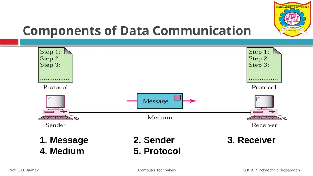
slide7. Components of Data Communication 1. Message 2. Sender 3. Receiver 4. Medium 5. Protocol Prof. S.B. Jadhav Computer Technology S.K.B.P. Polytechnic, Kopargaon<br>
slide8. Components of Data Communication Message- The message is the information (data) to be communicated. Popular forms of information include text, numbers, pictures, audio, and video.
Sender. The sender is the device that sends the data message. It can be a computer, workstation, telephone, video camera.
Receiver. The receiver is the device that receives the message. It can be a computer, workstation, telephone, television,& so on. Prof. S.B. Jadhav Computer Technology S.K.B.P. Polytechnic, Kopargaon<br>
slide9. Components of Data Communication Transmission medium. The transmission medium is the physical path by which a message travels from sender to receiver.
Examples of transmission media include twisted-pair, coaxial, fiber-optic, and radio waves.
Protocol. A protocol is a set of rules that govern data communications. It represents an agreement between the communicating devices. Without a protocol, two devices may be connected but not communicating, just as a person speaking French cannot be understood by a person who speaks only Japanese. Prof. S.B. Jadhav Computer Technology S.K.B.P. Polytechnic, Kopargaon<br>
slide10. Protocols and Standards Protocol is a set of rules that govern all aspect of data communication between computers on a network.
These rules include guidelines to regulate: access method, allowed physical topologies, types of cabling, and speed of data transfer.
A protocol defines what, how, when it communicated.
Protocols are to computers, what language is to humans. Since this article is in English, to understand it you must be able to read English. Similarly, for two devices on a network to successfully communicate, they must both understand the same protocols. Prof. S.B. Jadhav Computer Technology S.K.B.P. Polytechnic, Kopargaon<br>
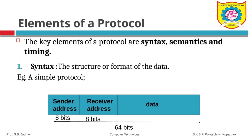
slide11. Elements of a Protocol The key elements of a protocol are syntax, semantics and timing. Syntax :The structure or format of the data.
Eg. A simple protocol; 64 bits 8 bits 8 bits Sender address Receiver address data Prof. S.B. Jadhav Computer Technology S.K.B.P. Polytechnic, Kopargaon<br>
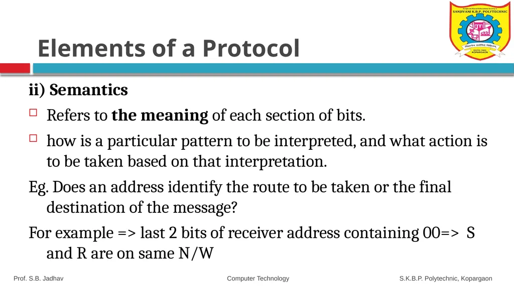
slide12. Elements of a Protocol ii) Semantics
Refers to the meaning of each section of bits.
how is a particular pattern to be interpreted, and what action is to be taken based on that interpretation.
Eg. Does an address identify the route to be taken or the final destination of the message?
For example => last 2 bits of receiver address containing 00=> S and R are on same N/W Prof. S.B. Jadhav Computer Technology S.K.B.P. Polytechnic, Kopargaon<br>
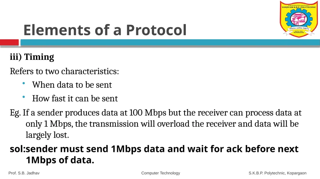
slide13. Elements of a Protocol iii) Timing
Refers to two characteristics:
When data to be sent
How fast it can be sent
Eg. If a sender produces data at 100 Mbps but the receiver can process data at only 1 Mbps, the transmission will overload the receiver and data will be largely lost.
sol:sender must send 1Mbps data and wait for ack before next 1Mbps of data. Prof. S.B. Jadhav Computer Technology S.K.B.P. Polytechnic, Kopargaon<br>
slide14. 1.2 Standards and Standards Organization<br>
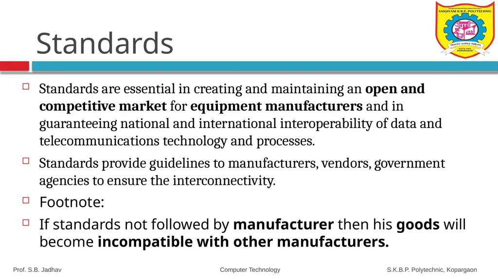
slide15. Standards Standards are essential in creating and maintaining an open and competitive market for equipment manufacturers and in guaranteeing national and international interoperability of data and telecommunications technology and processes.
Standards provide guidelines to manufacturers, vendors, government agencies to ensure the interconnectivity.
Footnote:
If standards not followed by manufacturer then his goods will become incompatible with other manufacturers. Prof. S.B. Jadhav Computer Technology S.K.B.P. Polytechnic, Kopargaon<br>
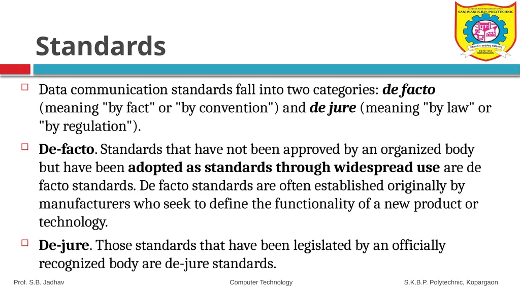
slide16. Standards Data communication standards fall into two categories: de facto (meaning "by fact" or "by convention") and de jure (meaning "by law" or "by regulation").
De-facto. Standards that have not been approved by an organized body but have been adopted as standards through widespread use are de facto standards. De facto standards are often established originally by manufacturers who seek to define the functionality of a new product or technology.
De-jure. Those standards that have been legislated by an officially recognized body are de-jure standards. Prof. S.B. Jadhav Computer Technology S.K.B.P. Polytechnic, Kopargaon<br>
slide17. Standards & Standards Organization Standards are developed by cooperation among standards creation committees, forums, and government regulatory agencies.
Standards Creation Committees
International Standards Organization (ISO)
International Telecommunications Union (ITU)
American National Standards Institute (ANSI)
Institute of Electrical and Electronics Engineers (IEEE)
Electronic Industries Association (EIA)
Internet Engineering Task Force (IETF) Prof. S.B. Jadhav Computer Technology S.K.B.P. Polytechnic, Kopargaon<br>
slide18. a) International Standards Organization (ISO) A multinational body whose membership is drawn mainly from the standards creation committees of various governments throughout the world
Dedicated to worldwide agreement on international standards in a variety of fields.
Currently includes 82 memberships industrialized nations.
Aims to facilitate the international exchange of goods and services by providing models for compatibility, improved quality, increased productivity and decreased prices. Prof. S.B. Jadhav Computer Technology S.K.B.P. Polytechnic, Kopargaon<br>
slide19. Also known as International Telecommunications Union-Telecommunication Standards Sector (ITU-T)
An international standards organization related to the United Nations that develops standards for telecommunications.
Two popular standards developed by ITU-T are:
i) V.32 series – transmission over phone lines
ii) X.25 series – transmission over public digital networks, email and directory services and ISDN., X.400 Email, X.500 Directory services
ISDN- Integrated Digital Services Network b) International Telecommunications Union (ITU) Prof. S.B. Jadhav Computer Technology S.K.B.P. Polytechnic, Kopargaon<br>
slide20. c) American National Standards Institute (ANSI) A non-profit corporation not affiliated with US government.
ANSI members include professional societies, industry associations, governmental and regulatory bodies, and consumer groups.
Discussing the internetwork planning and engineering, ISDN services, signaling, and architecture and optical hierarchy. Prof. S.B. Jadhav Computer Technology S.K.B.P. Polytechnic, Kopargaon<br>
slide21. The largest national professional group involved in developing standards for computing, communication, electrical engineering, and electronics.
Aims to advance theory, creativity and product quality in the fields of electrical engineering, electronics and radio.
It sponsored an important standard for local area networks called Project 802 (eg. 802.3, 802.4 and 802.5 standards.) d) Institute of Electrical and Electronics Engineers (IEEE) Prof. S.B. Jadhav Computer Technology S.K.B.P. Polytechnic, Kopargaon<br>
slide22. e) Electronic Industries Association (EIA) An association of electronics manufacturers in the US.
Provide activities include public awareness education and lobbying efforts in addition to standards development.
Responsible for developing the EIA-232-D and EIA-530 standards. Prof. S.B. Jadhav Computer Technology S.K.B.P. Polytechnic, Kopargaon<br>
slide23. f) Internet Engineering Task Force (IETF) Concerned with speeding the growth and evolution of Internet communications.
The standards body for the Internet itself
Reviews internet software and hardware. Prof. S.B. Jadhav Computer Technology S.K.B.P. Polytechnic, Kopargaon<br>
slide24. Internet Standards An Internet standard is a thoroughly tested specification that is useful to and adhered to by those who work with the Internet. It is a formalized regulation that must be followed.
There is a strict procedure by which a specification attains Internet standard status.
A specification begins as an Internet draft. An Internet draft is a working document (a work in progress) with no official status and a 6-month lifetime. Upon recommendation from the Internet authorities, a draft may be published as a Request for Comment (RFC). Each RFC is edited, assigned a number, and made available to all interested parties. RFCs go through maturity levels and are categorized according to their requirement level. Prof. S.B. Jadhav Computer Technology S.K.B.P. Polytechnic, Kopargaon<br>
slide25. Bandwidth, Data Transmission Rate, Baud Rate & Bits Per Second<br>
slide26. Bandwidth Bandwidth is also called as data transfer rate.
Moving data from one point to another, in a given time period (usually a second), is called bandwidth.
Bandwidth is indicated by bits (of data) per second (bps). Prof. S.B. Jadhav Computer Technology S.K.B.P. Polytechnic, Kopargaon<br>
slide27. Bandwidth of Signal Bandwidth is defined as the portion of electromagnetic spectrum occupied by a signal.
Bandwidth is the difference between the upper and lower frequency limits of signal.
Example:
Voice signal ranges from 20Hz to 20KHz,
BW=f2-f1=20000-20=19980Hz Prof. S.B. Jadhav Computer Technology S.K.B.P. Polytechnic, Kopargaon<br>
slide28. Channel Bandwidth Bandwidth of a channel is defined as maximum frequency it can allow to pass through it without attenuation and distortion.
Digital Bandwidth: the maximum bit rate that a medium can propagate through it.
For digital devices, An Internet connection via cable modem may provide 25 Mbps of bandwidth.
For analog devices, the bandwidth is expressed in cycles per second, or Hertz (Hz)<br>
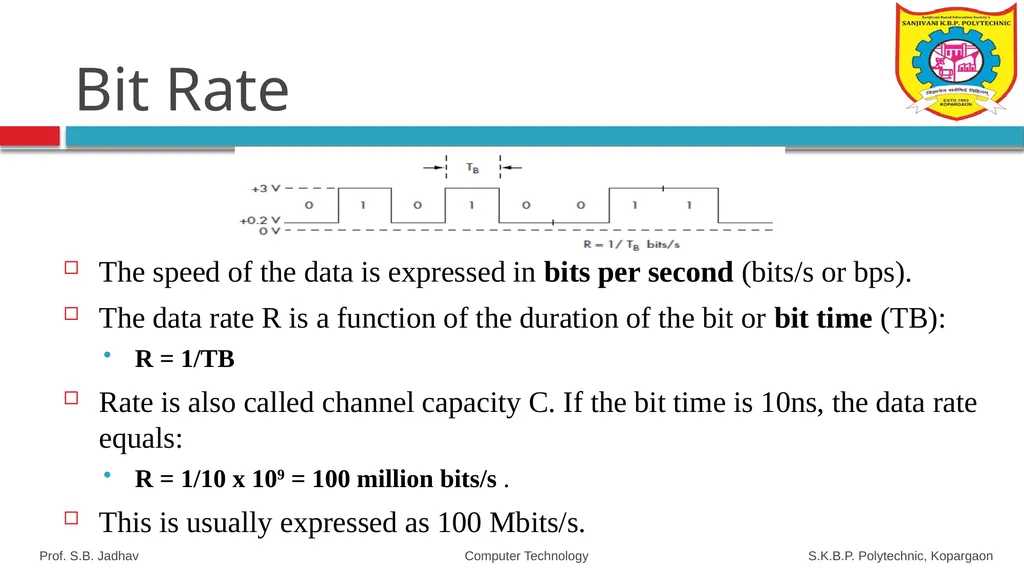
slide29. Bit Rate The speed of the data is expressed in bits per second (bits/s or bps).
The data rate R is a function of the duration of the bit or bit time (TB):
R = 1/TB
Rate is also called channel capacity C. If the bit time is 10ns, the data rate equals:
R = 1/10 x 109 = 100 million bits/s .
This is usually expressed as 100 Mbits/s. Prof. S.B. Jadhav Computer Technology S.K.B.P. Polytechnic, Kopargaon<br>
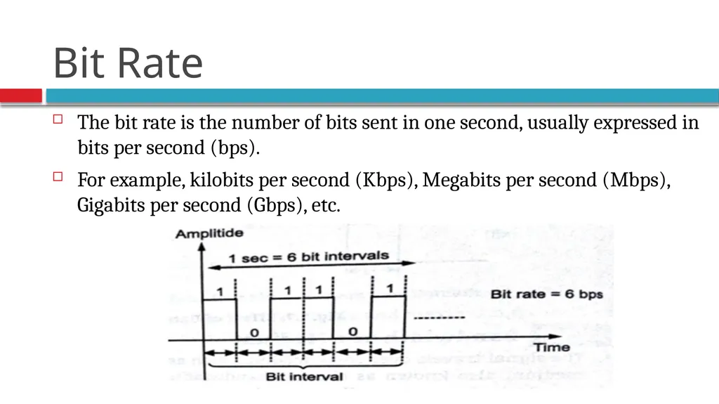
slide30. The bit rate is the number of bits sent in one second, usually expressed in bits per second (bps).
For example, kilobits per second (Kbps), Megabits per second (Mbps), Gigabits per second (Gbps), etc. Bit Rate<br>
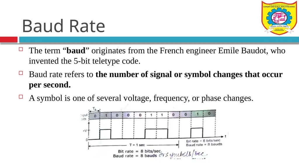
slide31. Baud Rate The term “baud” originates from the French engineer Emile Baudot, who invented the 5-bit teletype code.
Baud rate refers to the number of signal or symbol changes that occur per second.
A symbol is one of several voltage, frequency, or phase changes.<br>
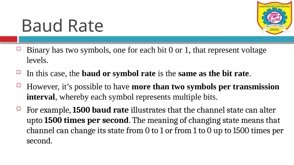
slide32. Baud Rate Binary has two symbols, one for each bit 0 or 1, that represent voltage levels.
In this case, the baud or symbol rate is the same as the bit rate.
However, it’s possible to have more than two symbols per transmission interval, whereby each symbol represents multiple bits.
For example, 1500 baud rate illustrates that the channel state can alter upto 1500 times per second. The meaning of changing state means that channel can change its state from 0 to 1 or from 1 to 0 up to 1500 times per second.<br>
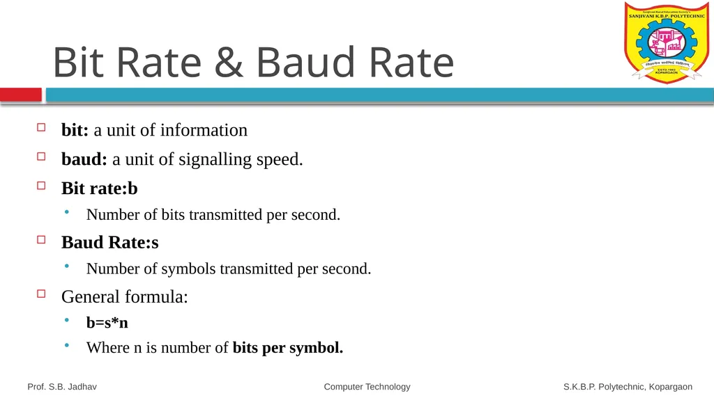
slide33. Bit Rate & Baud Rate bit: a unit of information
baud: a unit of signalling speed.
Bit rate:b
Number of bits transmitted per second.
Baud Rate:s
Number of symbols transmitted per second.
General formula:
b=s*n
Where n is number of bits per symbol. Prof. S.B. Jadhav Computer Technology S.K.B.P. Polytechnic, Kopargaon<br>
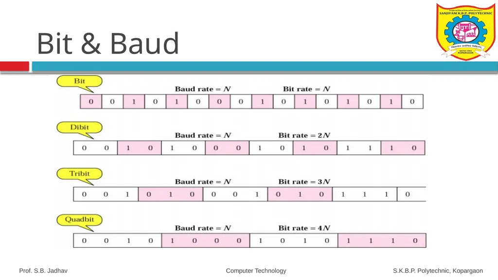
slide34. Bit & Baud Prof. S.B. Jadhav Computer Technology S.K.B.P. Polytechnic, Kopargaon<br>
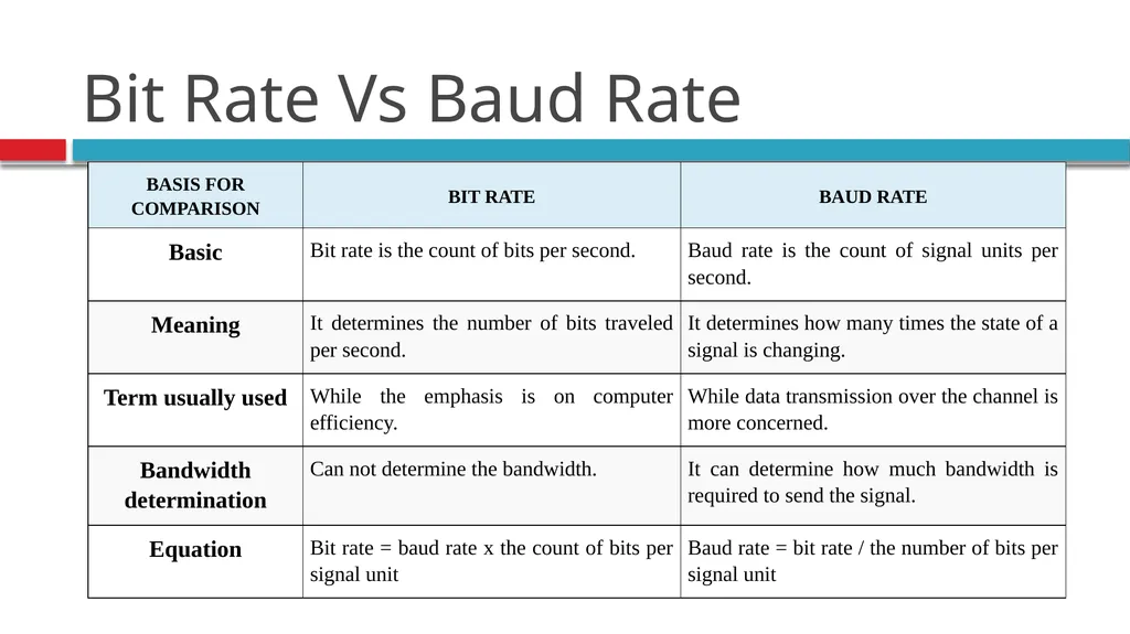
slide35. Bit Rate Vs Baud Rate<br>
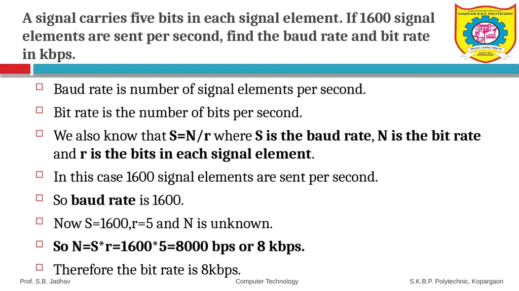
slide36. A signal carries five bits in each signal element. If 1600 signal elements are sent per second, find the baud rate and bit rate in kbps. Baud rate is number of signal elements per second.
Bit rate is the number of bits per second.
We also know that S=N/r where S is the baud rate, N is the bit rate and r is the bits in each signal element.
In this case 1600 signal elements are sent per second.
So baud rate is 1600.
Now S=1600,r=5 and N is unknown.
So N=S*r=1600*5=8000 bps or 8 kbps.
Therefore the bit rate is 8kbps. Prof. S.B. Jadhav Computer Technology S.K.B.P. Polytechnic, Kopargaon<br>
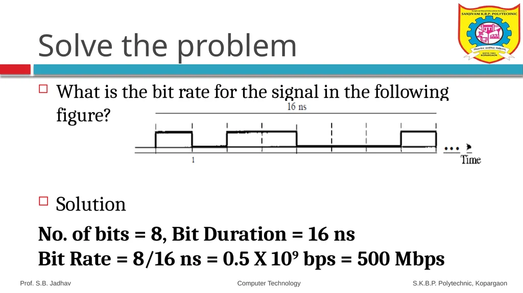
slide37. Solve the problem What is the bit rate for the signal in the following figure?
Solution
No. of bits = 8, Bit Duration = 16 ns Bit Rate = 8/16 ns = 0.5 X 10⁹ bps = 500 Mbps Prof. S.B. Jadhav Computer Technology S.K.B.P. Polytechnic, Kopargaon<br>
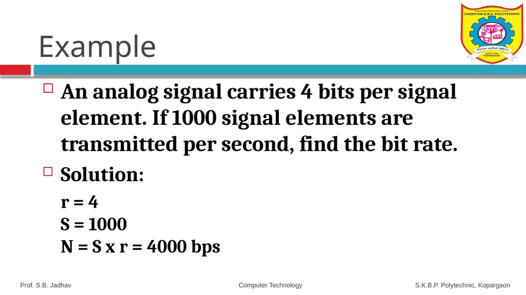
slide38. Example An analog signal carries 4 bits per signal element. If 1000 signal elements are transmitted per second, find the bit rate.
Solution:
r = 4 S = 1000 N = S x r = 4000 bps Prof. S.B. Jadhav Computer Technology S.K.B.P. Polytechnic, Kopargaon<br>
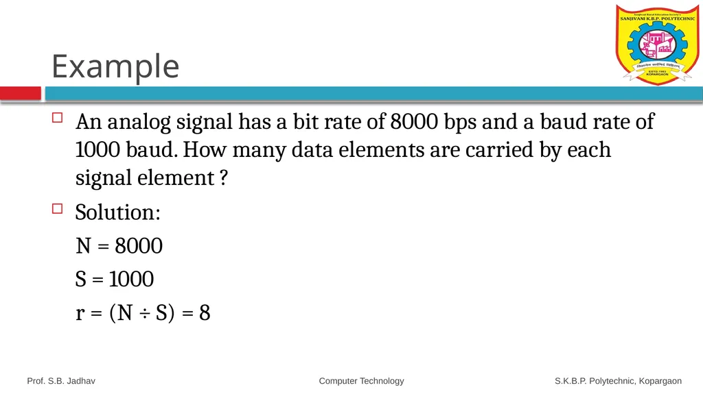
slide39. Example An analog signal has a bit rate of 8000 bps and a baud rate of 1000 baud. How many data elements are carried by each signal element ?
Solution:
N = 8000
S = 1000
r = (N ÷ S) = 8 Prof. S.B. Jadhav Computer Technology S.K.B.P. Polytechnic, Kopargaon<br>
slide40. Modes of Communication<br>
slide41. Modes of Communication Communication between two devices ie sender and receiver can be of three types:
Simplex
Half-Duplex
Full-Duplex Prof. S.B. Jadhav Computer Technology S.K.B.P. Polytechnic, Kopargaon<br>
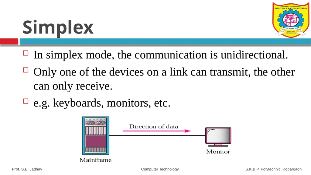
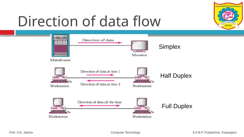
slide42. Simplex In simplex mode, the communication is unidirectional.
Only one of the devices on a link can transmit, the other can only receive.
e.g. keyboards, monitors, etc. Prof. S.B. Jadhav Computer Technology S.K.B.P. Polytechnic, Kopargaon<br>
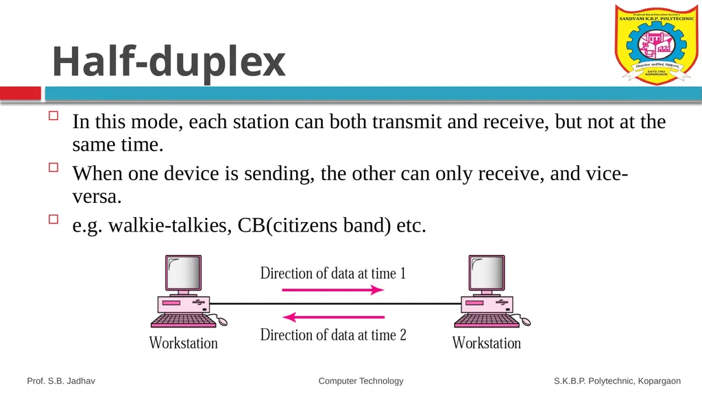
slide43. Half-duplex In this mode, each station can both transmit and receive, but not at the same time.
When one device is sending, the other can only receive, and vice-versa.
e.g. walkie-talkies, CB(citizens band) etc. Prof. S.B. Jadhav Computer Technology S.K.B.P. Polytechnic, Kopargaon<br>
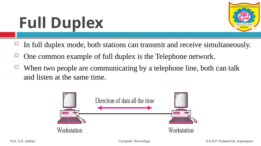
slide44. Full Duplex In full duplex mode, both stations can transmit and receive simultaneously.
One common example of full duplex is the Telephone network.
When two people are communicating by a telephone line, both can talk and listen at the same time. Prof. S.B. Jadhav Computer Technology S.K.B.P. Polytechnic, Kopargaon<br>
slide45. Direction of data flow Simplex Half Duplex Full Duplex Prof. S.B. Jadhav Computer Technology S.K.B.P. Polytechnic, Kopargaon<br>
slide46. Analog and Digital Signal<br>
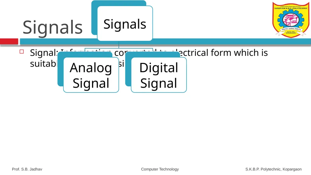
slide47. Signals Signal: Information converted to electrical form which is suitable for transmission. Prof. S.B. Jadhav Computer Technology S.K.B.P. Polytechnic, Kopargaon<br>
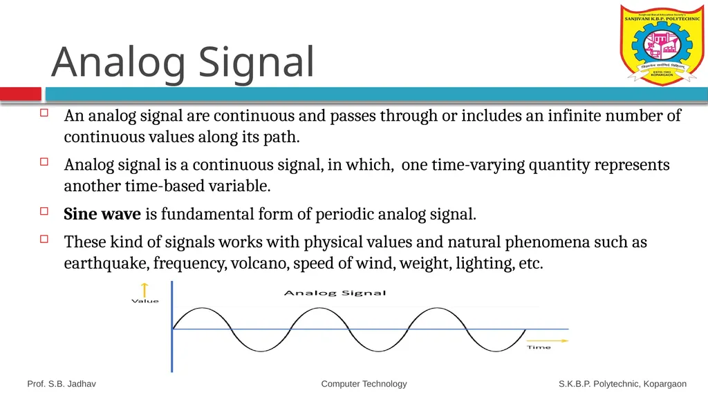
slide48. Analog Signal An analog signal are continuous and passes through or includes an infinite number of continuous values along its path.
Analog signal is a continuous signal, in which, one time-varying quantity represents another time-based variable.
Sine wave is fundamental form of periodic analog signal.
These kind of signals works with physical values and natural phenomena such as earthquake, frequency, volcano, speed of wind, weight, lighting, etc. Prof. S.B. Jadhav Computer Technology S.K.B.P. Polytechnic, Kopargaon<br>
slide49. Characteristics Of Analog Signal These type of electronic signals are time-varying
Minimum and maximum values which is either positive or negative.
It can be either periodic or non-periodic.
Analog Signal works on continuous data.
The accuracy of the analog signal is not high when compared to the digital signal.
It helps you to measure natural or physical values.
Analog signal output form is like Curve, Line, or Graph, so it may not be meaningful to all.<br>
slide50. Advantages of Analog Signals Easier in processing
Best suited for audio and video transmission.
It has a low cost and is portable.
It has a much higher density so that it can present more refined information.
Not necessary to buy a new graphics board.
Uses less bandwidth than digital sounds
It is the natural form of a sound.<br>
slide51. Disadvantages of Analog Signals Analog tends to have a lower quality signal than digital.
The cables are sensitive to external influences.
The cost of the Analog wire is high and not easily portable.
Low availability of models with digital interfaces.
It offers limitations in editing
Quality is easily lost<br>
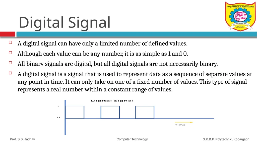
slide52. Digital Signal A digital signal can have only a limited number of defined values.
Although each value can be any number, it is as simple as 1 and 0.
All binary signals are digital, but all digital signals are not necessarily binary.
A digital signal is a signal that is used to represent data as a sequence of separate values at any point in time. It can only take on one of a fixed number of values. This type of signal represents a real number within a constant range of values. Prof. S.B. Jadhav Computer Technology S.K.B.P. Polytechnic, Kopargaon<br>
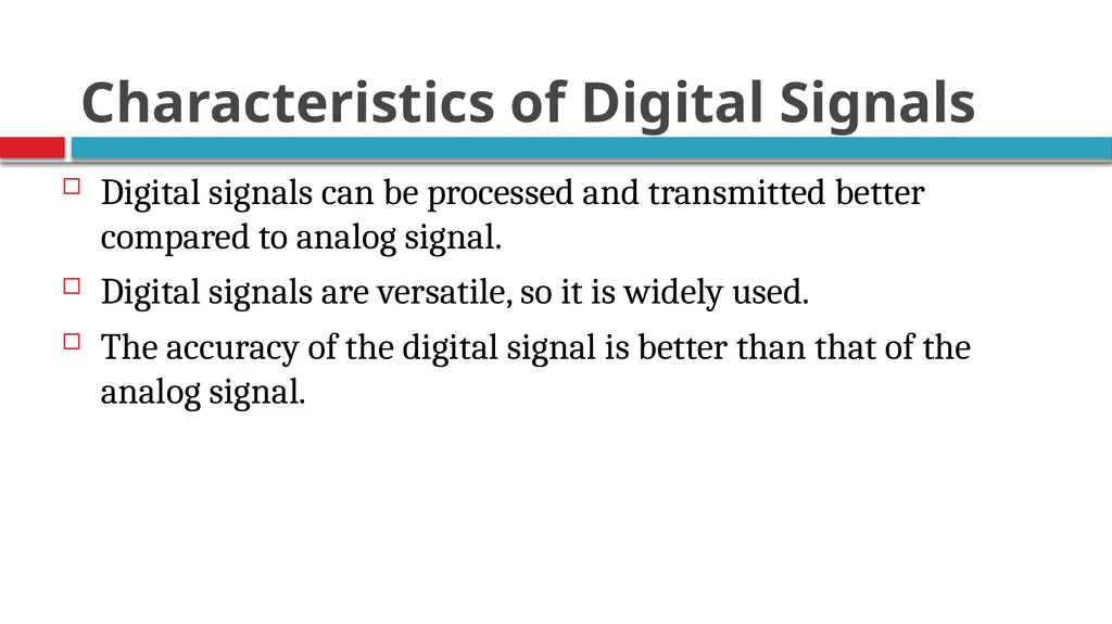
slide53. Characteristics of Digital Signals Digital signals can be processed and transmitted better compared to analog signal.
Digital signals are versatile, so it is widely used.
The accuracy of the digital signal is better than that of the analog signal.<br>
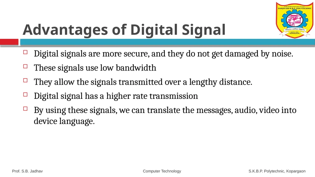
slide54. Advantages of Digital Signal Digital signals are more secure, and they do not get damaged by noise.
These signals use low bandwidth
They allow the signals transmitted over a lengthy distance.
Digital signal has a higher rate transmission
By using these signals, we can translate the messages, audio, video into device language. Prof. S.B. Jadhav Computer Technology S.K.B.P. Polytechnic, Kopargaon<br>
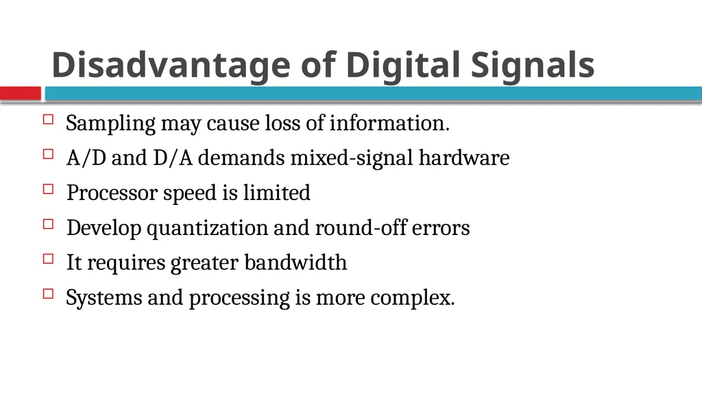
slide55. Disadvantage of Digital Signals Sampling may cause loss of information.
A/D and D/A demands mixed-signal hardware
Processor speed is limited
Develop quantization and round-off errors
It requires greater bandwidth
Systems and processing is more complex.<br>
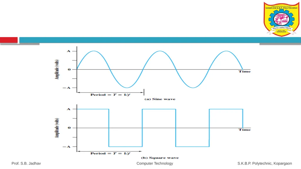
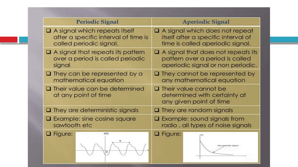
slide57. Periodic and Non-periodic signals A signal is periodic signal if it completes a pattern within measurable time frame.
A periodic signal is characterised by amplitude, frequency and phase.
Mathematically: v(t)=V sin(2πft+θ)
V:Peak Amplitude
F:frequency
t:Time(seconds)
θ:Phase(degree or radians) Prof. S.B. Jadhav Computer Technology S.K.B.P. Polytechnic, Kopargaon<br>
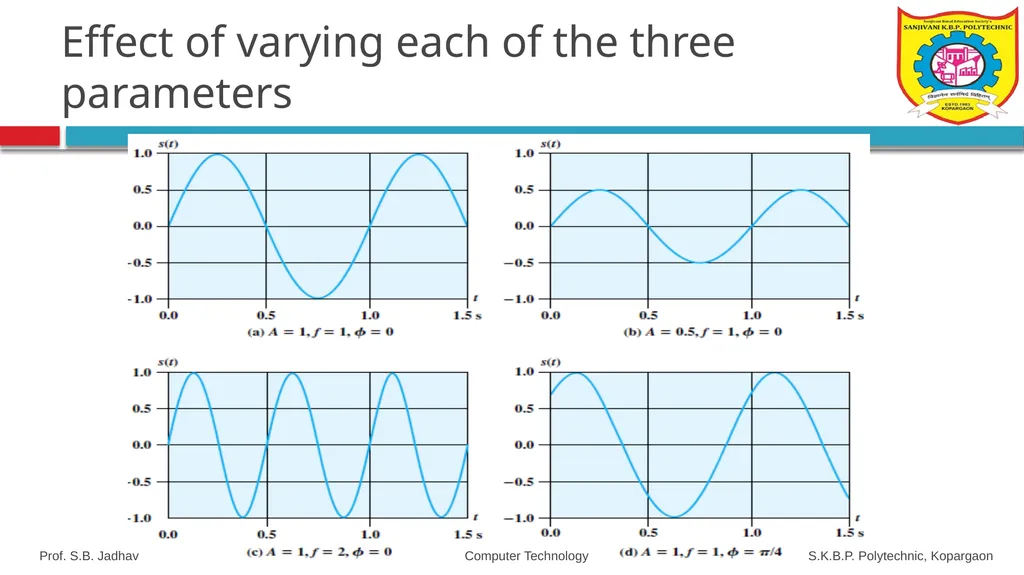
slide58. Amplitude is the highest height of the signal, maximum value or strength of the signal over time; typically, this value is measured in volts.
frequency is the rate [in cycles per second, or Hertz (Hz)] at which the signal repeats., and
Phase is a measure of the relative position in time within a single period of a signal
An analog signal is not resistant toward the noise, therefore; it faces distortion as well as reduces the transmission quality. Prof. S.B. Jadhav Computer Technology S.K.B.P. Polytechnic, Kopargaon<br>
slide59. Effect of varying each of the three parameters Prof. S.B. Jadhav Computer Technology S.K.B.P. Polytechnic, Kopargaon<br>
slide60. Prof. S.B. Jadhav Computer Technology S.K.B.P. Polytechnic, Kopargaon<br>
slide61. Non Periodic Signal A signal that does not repeats its pattern over a period is called aperiodic signal or non periodic.
Both the Analog and Digital can be periodic or aperiodic: but in data communication periodic analog signals and aperiodic digital signals are used. Prof. S.B. Jadhav Computer Technology S.K.B.P. Polytechnic, Kopargaon<br>
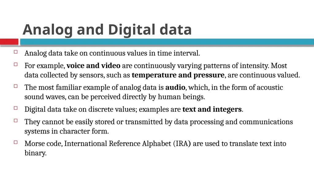
slide63. Analog and Digital data Analog data take on continuous values in time interval.
For example, voice and video are continuously varying patterns of intensity. Most data collected by sensors, such as temperature and pressure, are continuous valued.
The most familiar example of analog data is audio, which, in the form of acoustic sound waves, can be perceived directly by human beings.
Digital data take on discrete values; examples are text and integers.
They cannot be easily stored or transmitted by data processing and communications systems in character form.
Morse code, International Reference Alphabet (IRA) are used to translate text into binary.<br>
slide64. Analog Transmission
Digital Transmission Prof. S.B. Jadhav Computer Technology S.K.B.P. Polytechnic, Kopargaon<br>
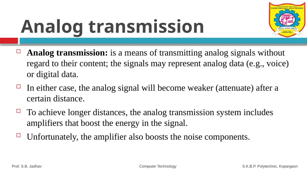
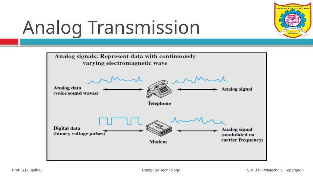
slide65. Analog transmission Analog transmission: is a means of transmitting analog signals without regard to their content; the signals may represent analog data (e.g., voice) or digital data.
In either case, the analog signal will become weaker (attenuate) after a certain distance.
To achieve longer distances, the analog transmission system includes amplifiers that boost the energy in the signal.
Unfortunately, the amplifier also boosts the noise components. Prof. S.B. Jadhav Computer Technology S.K.B.P. Polytechnic, Kopargaon<br>
slide66. Analog Transmission Prof. S.B. Jadhav Computer Technology S.K.B.P. Polytechnic, Kopargaon<br>
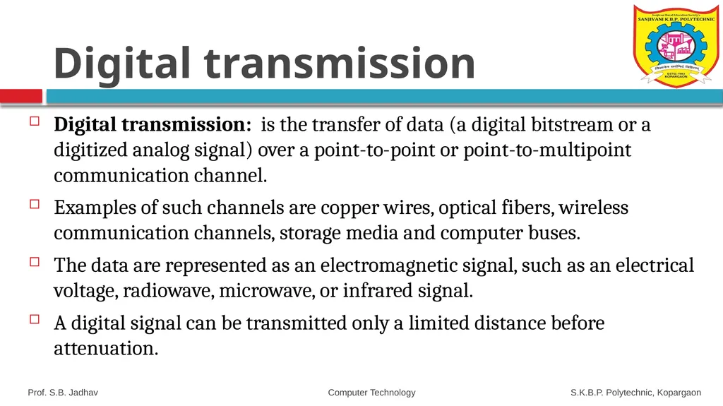
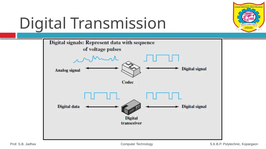
slide67. Digital transmission Digital transmission: is the transfer of data (a digital bitstream or a digitized analog signal) over a point-to-point or point-to-multipoint communication channel.
Examples of such channels are copper wires, optical fibers, wireless communication channels, storage media and computer buses.
The data are represented as an electromagnetic signal, such as an electrical voltage, radiowave, microwave, or infrared signal.
A digital signal can be transmitted only a limited distance before attenuation. Prof. S.B. Jadhav Computer Technology S.K.B.P. Polytechnic, Kopargaon<br>
slide68. Digital Transmission Prof. S.B. Jadhav Computer Technology S.K.B.P. Polytechnic, Kopargaon<br>
slide69. Prof. S.B. Jadhav Computer Technology S.K.B.P. Polytechnic, Kopargaon<br>
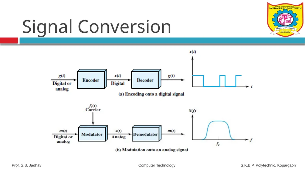
slide70. Both analog and digital information can be encoded as either analog or digital signals.
The particular encoding that is chosen depends on the specific requirements to be met and the media and communications facilities available. Prof. S.B. Jadhav Computer Technology S.K.B.P. Polytechnic, Kopargaon Signal Conversion<br>
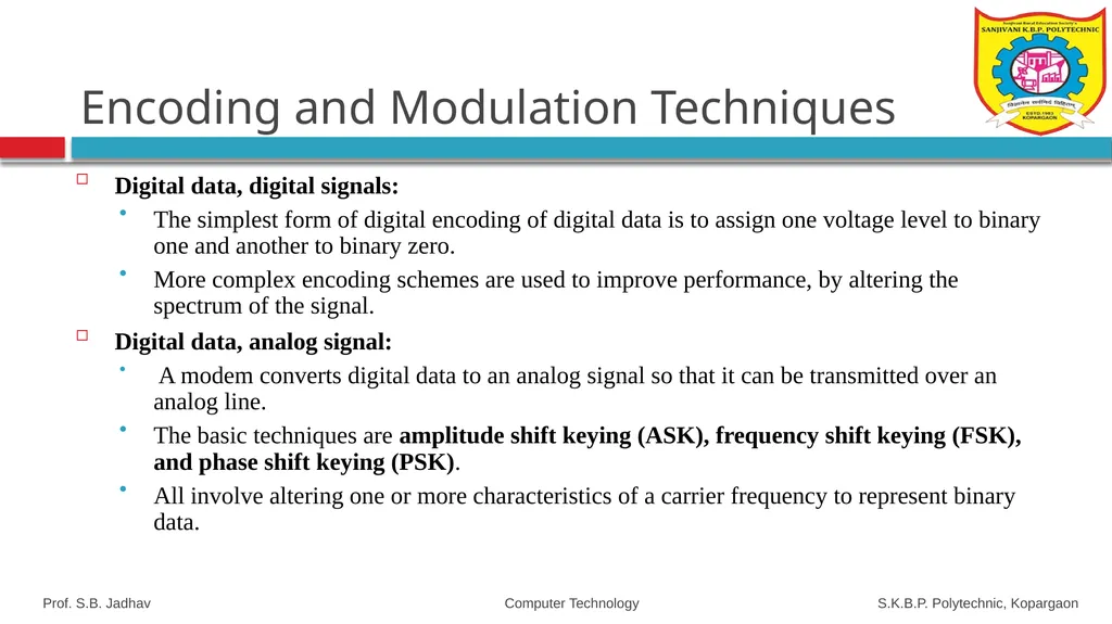
slide71. Digital data, digital signals:
The simplest form of digital encoding of digital data is to assign one voltage level to binary one and another to binary zero.
More complex encoding schemes are used to improve performance, by altering the spectrum of the signal.
Digital data, analog signal:
A modem converts digital data to an analog signal so that it can be transmitted over an analog line.
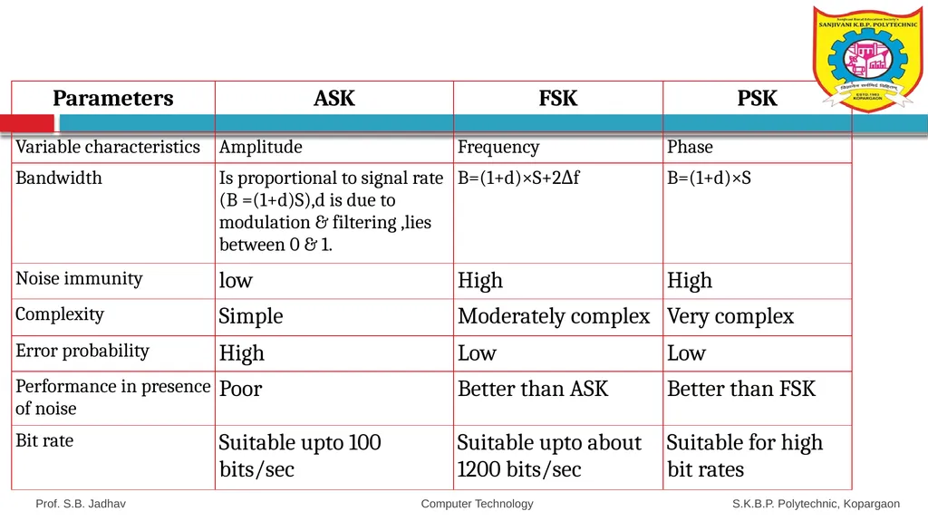
The basic techniques are amplitude shift keying (ASK), frequency shift keying (FSK), and phase shift keying (PSK).
All involve altering one or more characteristics of a carrier frequency to represent binary data. Prof. S.B. Jadhav Computer Technology S.K.B.P. Polytechnic, Kopargaon Encoding and Modulation Techniques<br>
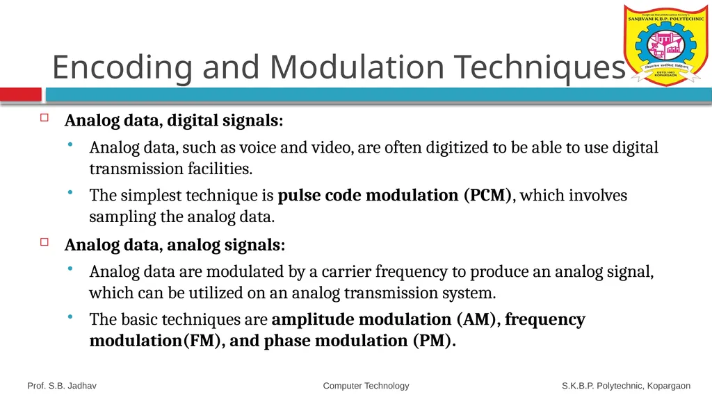
slide72. Analog data, digital signals:
Analog data, such as voice and video, are often digitized to be able to use digital transmission facilities.
The simplest technique is pulse code modulation (PCM), which involves sampling the analog data.
Analog data, analog signals:
Analog data are modulated by a carrier frequency to produce an analog signal, which can be utilized on an analog transmission system.
The basic techniques are amplitude modulation (AM), frequency modulation(FM), and phase modulation (PM). Prof. S.B. Jadhav Computer Technology S.K.B.P. Polytechnic, Kopargaon Encoding and Modulation Techniques<br>
slide73. Signal Conversion Prof. S.B. Jadhav Computer Technology S.K.B.P. Polytechnic, Kopargaon<br>
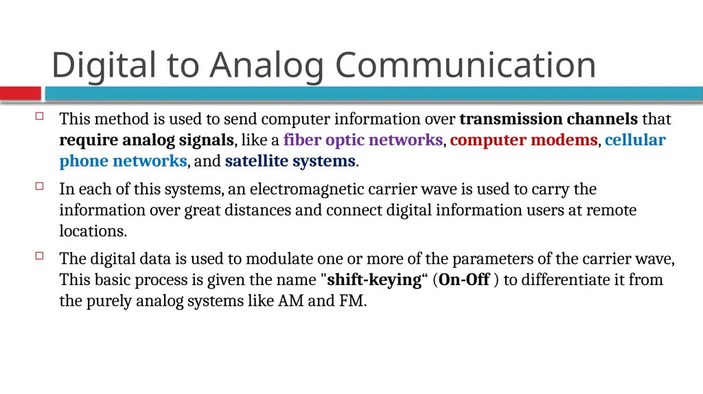
slide74. Digital to Analog Communication This method is used to send computer information over transmission channels that require analog signals, like a fiber optic networks, computer modems, cellular phone networks, and satellite systems.
In each of this systems, an electromagnetic carrier wave is used to carry the information over great distances and connect digital information users at remote locations.
The digital data is used to modulate one or more of the parameters of the carrier wave, This basic process is given the name "shift-keying“ (On-Off ) to differentiate it from the purely analog systems like AM and FM.<br>
slide75. Digital to Analog Conversion The case of transmitting digital data using analog signals.
The most familiar use is transmitting digital data through the public telephone network.
The telephone network was designed to receive, switch, and transmit analog signals in the voice-frequency range of about 300 to 3400 Hz.
Thus digital devices are attached to the network via a modem (modulator-demodulator), which converts digital data to analog signals, and vice versa. Prof. S.B. Jadhav Computer Technology S.K.B.P. Polytechnic, Kopargaon<br>
slide76. Digital to Analog Digital-to-analog conversion is the process of changing one of the characteristics of an analog signal based on the information in digital data.
A sine wave is defined by three characteristics: amplitude, frequency, and phase.
When we change anyone of these characteristics, we create a different version of that wave.
So, by changing one characteristic of a simple electric signal, we can use it to represent digital data Prof. S.B. Jadhav Computer Technology S.K.B.P. Polytechnic, Kopargaon<br>
slide77. Modulation or Encoding Modulation involves operation on one or more of the three characteristics of a carrier signal: amplitude, frequency, and phase.
Accordingly, there are three basic encoding or modulation techniques for transforming digital data into Analog signals:
Amplitude Shift Keying (ASK),
Frequency Shift Keying (FSK), and
Phase Shift Keying (PSK). Prof. S.B. Jadhav Computer Technology S.K.B.P. Polytechnic, Kopargaon<br>
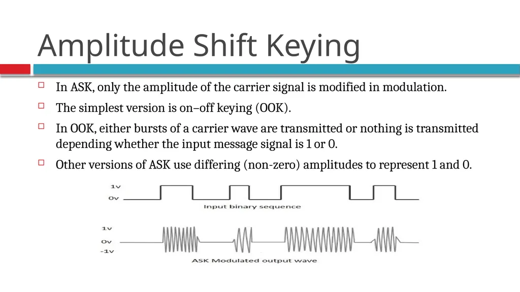
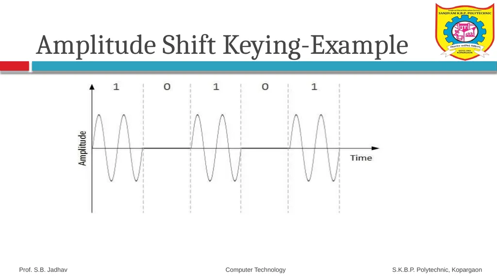
slide78. Amplitude Shift Keying ASK is the digital carrier Modulation in which amplitude of carrier will take one of the two values in response to 0 or 1 value of digital data.
Amplitude Shift Keying (ASK) is a type of Amplitude Modulation which represents the binary data in the form of variations in the amplitude of a signal.
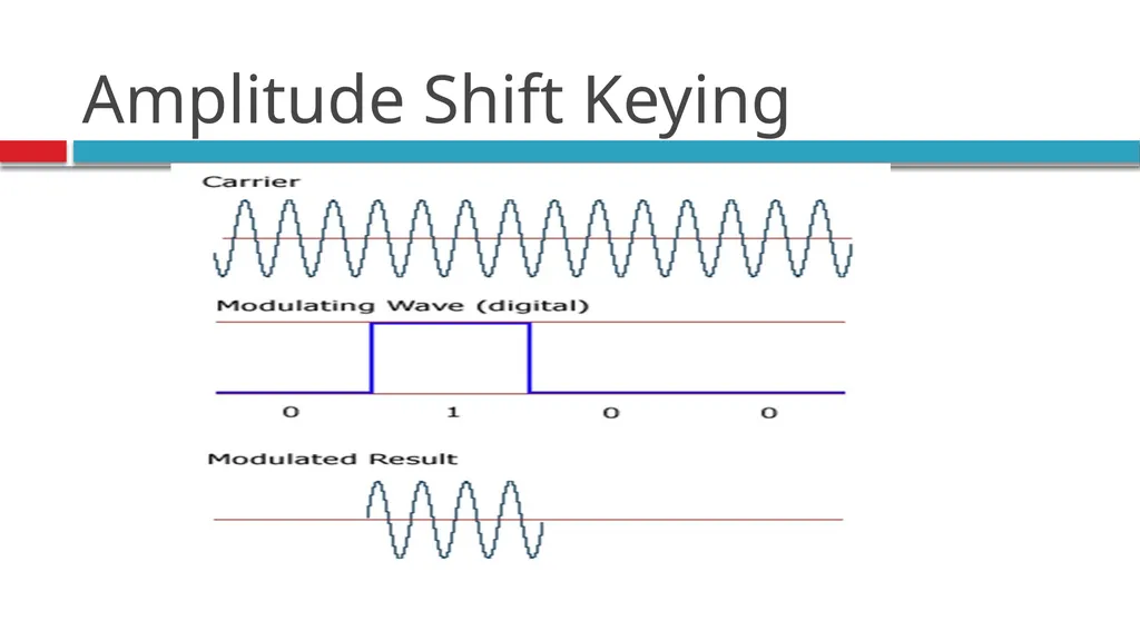
Any modulated signal has a high frequency carrier. The binary signal when ASK modulated, gives a zero value for Low input while it gives the carrier output for High input. Prof. S.B. Jadhav Computer Technology S.K.B.P. Polytechnic, Kopargaon<br>
slide79. In ASK, only the amplitude of the carrier signal is modified in modulation.
The simplest version is on–off keying (OOK).
In OOK, either bursts of a carrier wave are transmitted or nothing is transmitted depending whether the input message signal is 1 or 0.
Other versions of ASK use differing (non-zero) amplitudes to represent 1 and 0. Amplitude Shift Keying<br>
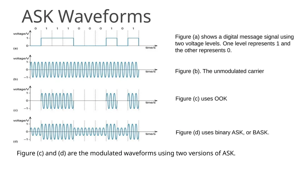
slide80. ASK Waveforms Figure (c) and (d) are the modulated waveforms using two versions of ASK. Figure (a) shows a digital message signal using two voltage levels. One level represents 1 and the other represents 0. Figure (b). The unmodulated carrier Figure (c) uses OOK Figure (d) uses binary ASK, or BASK.<br>
slide81. Amplitude Shift Keying<br>
slide82. Prof. S.B. Jadhav Computer Technology S.K.B.P. Polytechnic, Kopargaon Amplitude Shift Keying<br>
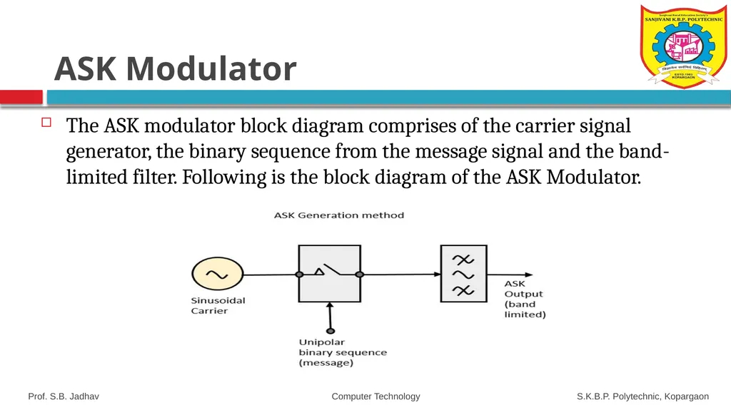
slide83. ASK Modulator The ASK modulator block diagram comprises of the carrier signal generator, the binary sequence from the message signal and the band-limited filter. Following is the block diagram of the ASK Modulator. Prof. S.B. Jadhav Computer Technology S.K.B.P. Polytechnic, Kopargaon<br>
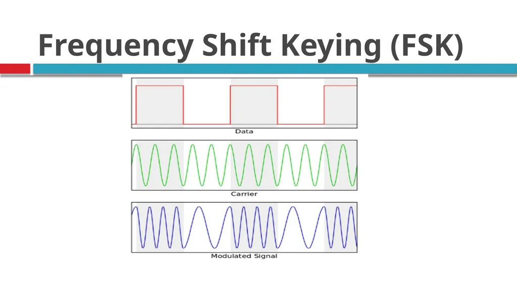
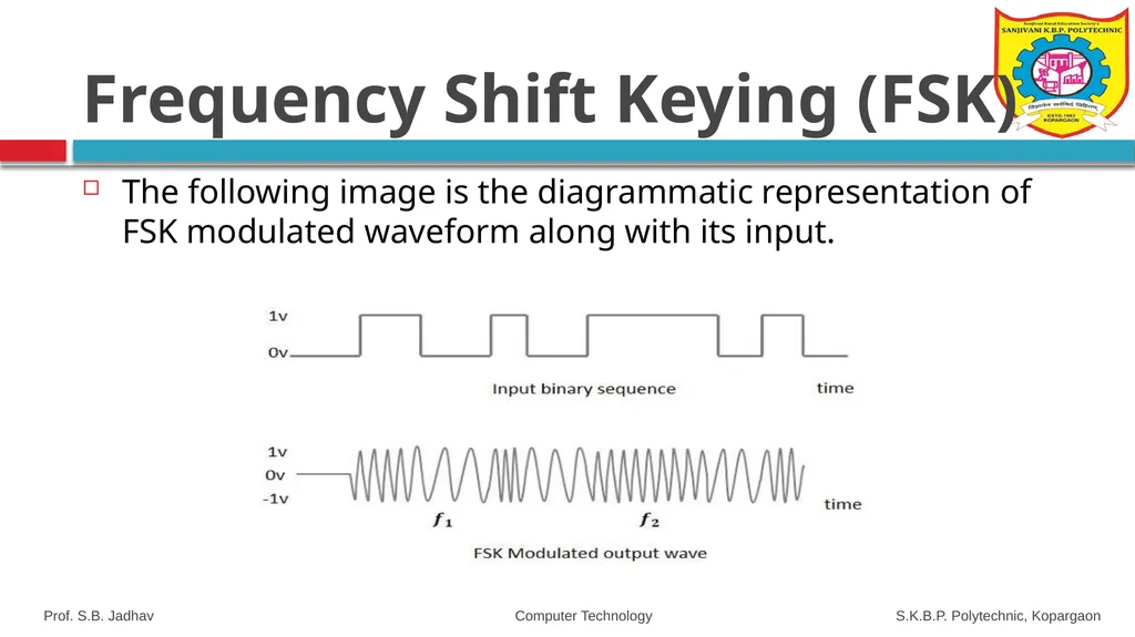
slide84. Frequency Shift Keying (FSK) Frequency Shift Keying (FSK) is the digital modulation technique in which the frequency of the carrier signal varies according to the digital signal changes. FSK is a scheme of frequency modulation.
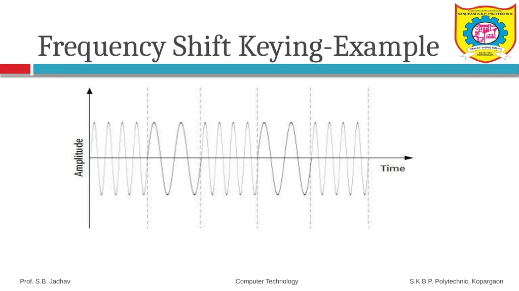
The output of a FSK modulated wave is high-in-frequency for a binary High input and is low-in-frequency for a binary Low input. The binary 1s and 0s are called Mark and Space frequencies. Prof. S.B. Jadhav Computer Technology S.K.B.P. Polytechnic, Kopargaon<br>
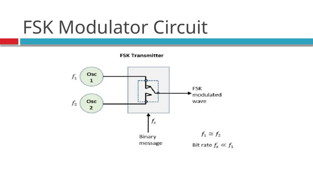
slide85. Frequency Shift Keying(FSK) In FSK, frequency of sinusoidal carrier is shifted between two discrete values.
One of these frequencies (f1) represents a binary 1 and other frequency (f2) represents binary 0.
There is no change in amplitude of carrier.
It consists of voltage controlled oscillators (VCO) which produce sinewave at frequencies f1 and f0.
Corresponding to "binary 0 "input, the VCO produces a sinewave of
frequency f0 whereas corresponding to binary 1 input VCO produces
a sinewave of frequency f1.<br>
slide86. Frequency Shift Keying (FSK)<br>
slide87. FSK Modulator Circuit<br>
slide88. The following image is the diagrammatic representation of FSK modulated waveform along with its input. Prof. S.B. Jadhav Computer Technology S.K.B.P. Polytechnic, Kopargaon Frequency Shift Keying (FSK)<br>
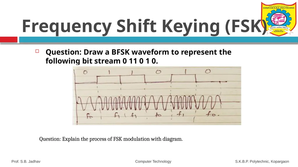
slide89. Question: Draw a BFSK waveform to represent the following bit stream 0 11 0 1 0. Prof. S.B. Jadhav Computer Technology S.K.B.P. Polytechnic, Kopargaon Frequency Shift Keying (FSK) Question: Explain the process of FSK modulation with diagram.<br>
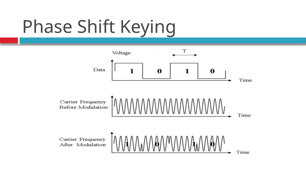
slide90. Phase Shift Keying (PSK) The phase of the carrier wave at the beginning of the pulse is changed between discrete values.
Phase-shift keying (PSK) is a digital to analog modulation scheme based on changing, or modulating, the initial phase of a carrier signal.
PSK is used to represent digital information, such as binary digits zero (0) and one (1).
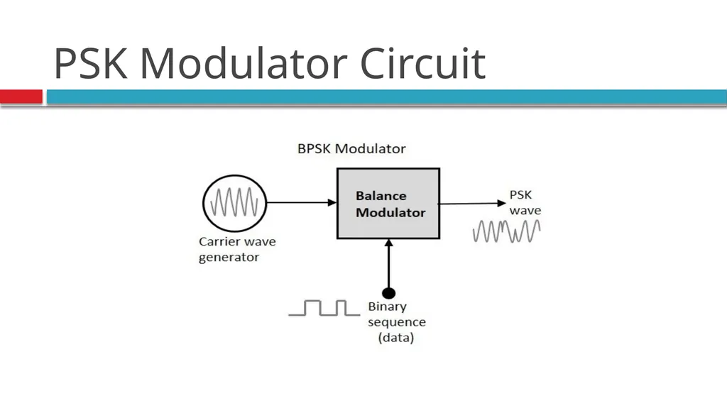
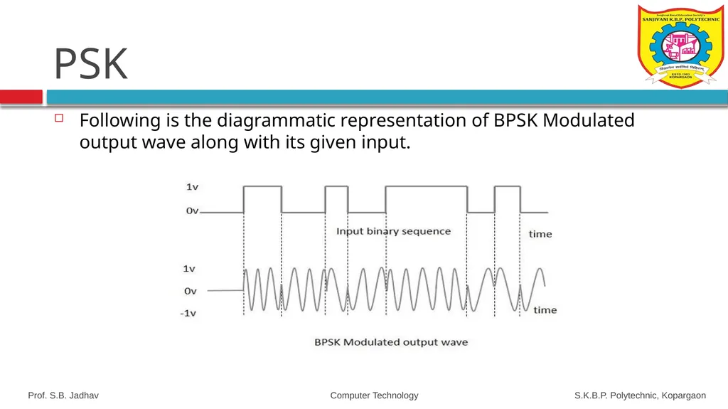
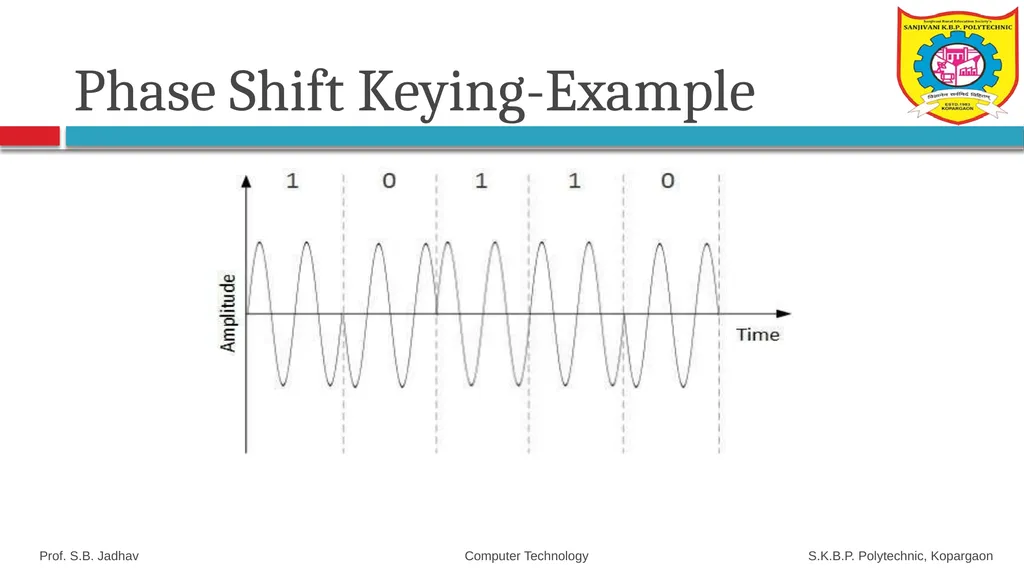
The modulation of PSK is done using a balance modulator, which multiplies the two signals applied at the input. For a zero binary input, the phase will be 180° and for a high input, the phase reversal is of 0°.
PSK technique is widely used for wireless LANs, bio-metric, contactless operations, along with RFID and Bluetooth communications. Prof. S.B. Jadhav Computer Technology S.K.B.P. Polytechnic, Kopargaon<br>
slide91. Types of PSK PSK is of two types, depending upon the phases the signal gets shifted. They are
Binary Phase Shift Keying (BPSK)
This is also called as 2-phase PSK or Phase Reversal Keying. In this technique, the sine wave carrier takes two phase reversals such as 0° and 180°.
BPSK is basically a Double Side Band Suppressed Carrier (DSBSC) modulation scheme, for message being the digital information.
Quadrature Phase Shift Keying (QPSK)
This is the phase shift keying technique, in which the sine wave carrier takes four phase reversals such as 0°, 90°, 180°, and 270°.
If this kind of techniques are further extended, PSK can be done by eight or sixteen values also, depending upon the requirement. Prof. S.B. Jadhav Computer Technology S.K.B.P. Polytechnic, Kopargaon<br>
slide92. Phase Shift Keying<br>
slide93. PSK Modulator Circuit<br>
slide94. PSK Following is the diagrammatic representation of BPSK Modulated output wave along with its given input. Prof. S.B. Jadhav Computer Technology S.K.B.P. Polytechnic, Kopargaon<br>
slide95. Amplitude Shift Keying-Example Prof. S.B. Jadhav Computer Technology S.K.B.P. Polytechnic, Kopargaon<br>
slide96. Frequency Shift Keying-Example Prof. S.B. Jadhav Computer Technology S.K.B.P. Polytechnic, Kopargaon<br>
slide97. Phase Shift Keying-Example Prof. S.B. Jadhav Computer Technology S.K.B.P. Polytechnic, Kopargaon<br>
slide98. Prof. S.B. Jadhav Computer Technology S.K.B.P. Polytechnic, Kopargaon<br>
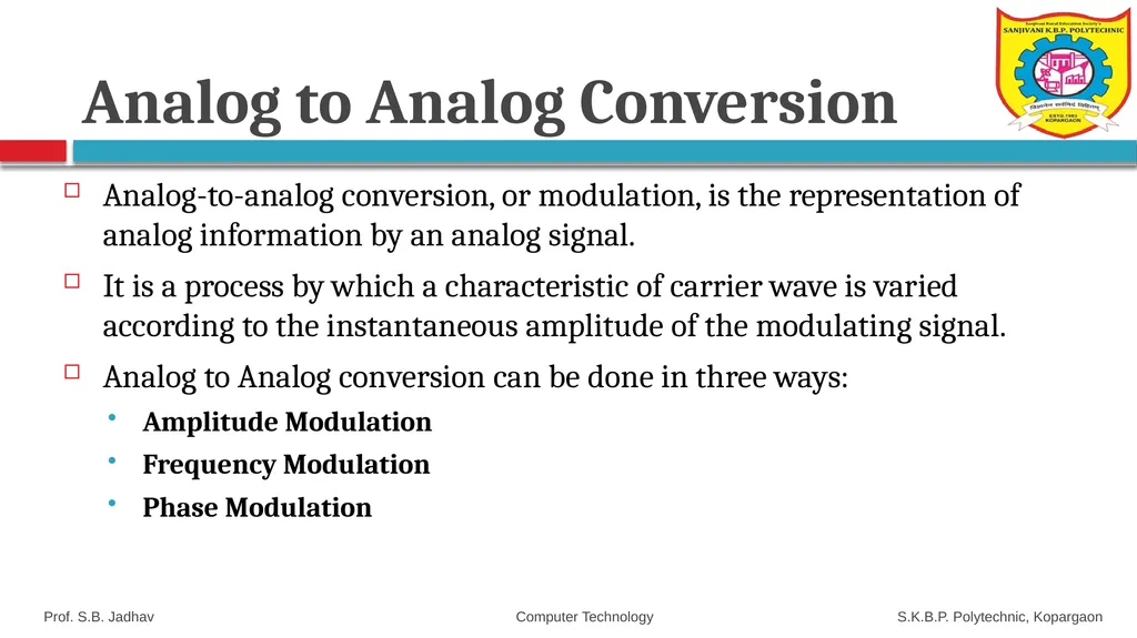
slide99. Analog to Analog Conversion Analog-to-analog conversion, or modulation, is the representation of analog information by an analog signal.
It is a process by which a characteristic of carrier wave is varied according to the instantaneous amplitude of the modulating signal.
Analog to Analog conversion can be done in three ways:
Amplitude Modulation
Frequency Modulation
Phase Modulation Prof. S.B. Jadhav Computer Technology S.K.B.P. Polytechnic, Kopargaon<br>
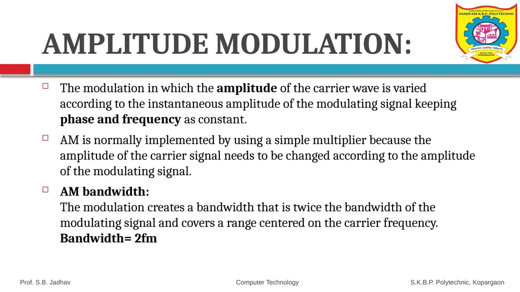
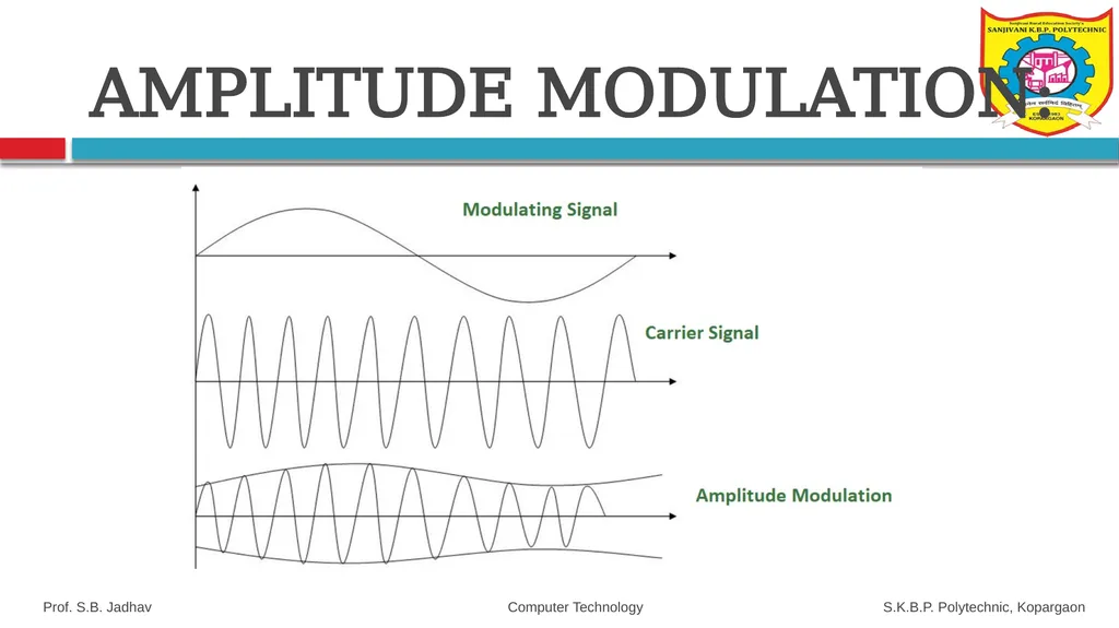
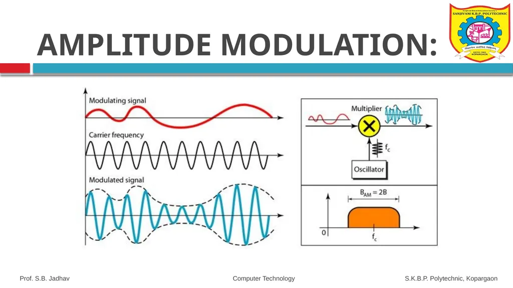
slide100. AMPLITUDE MODULATION: The modulation in which the amplitude of the carrier wave is varied according to the instantaneous amplitude of the modulating signal keeping phase and frequency as constant.
AM is normally implemented by using a simple multiplier because the amplitude of the carrier signal needs to be changed according to the amplitude of the modulating signal.
AM bandwidth: The modulation creates a bandwidth that is twice the bandwidth of the modulating signal and covers a range centered on the carrier frequency. Bandwidth= 2fm Prof. S.B. Jadhav Computer Technology S.K.B.P. Polytechnic, Kopargaon<br>
slide101. Prof. S.B. Jadhav Computer Technology S.K.B.P. Polytechnic, Kopargaon AMPLITUDE MODULATION:<br>
slide102. Prof. S.B. Jadhav Computer Technology S.K.B.P. Polytechnic, Kopargaon AMPLITUDE MODULATION:<br>
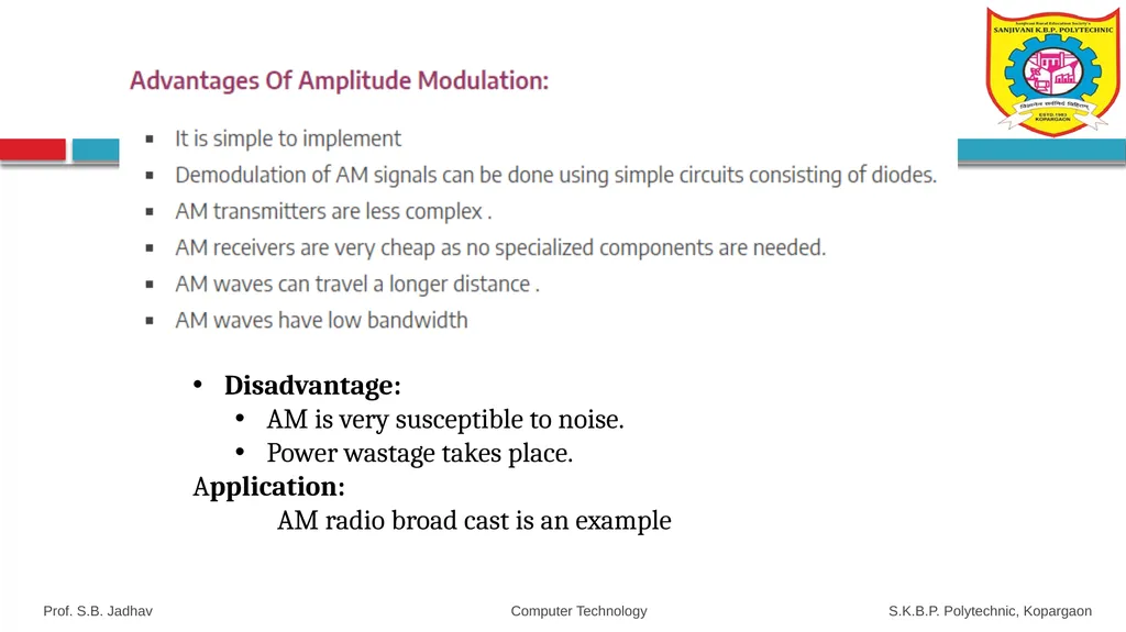
slide103. Disadvantage:
AM is very susceptible to noise.
Power wastage takes place.
Application:
AM radio broad cast is an example Prof. S.B. Jadhav Computer Technology S.K.B.P. Polytechnic, Kopargaon<br>
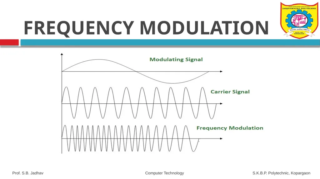
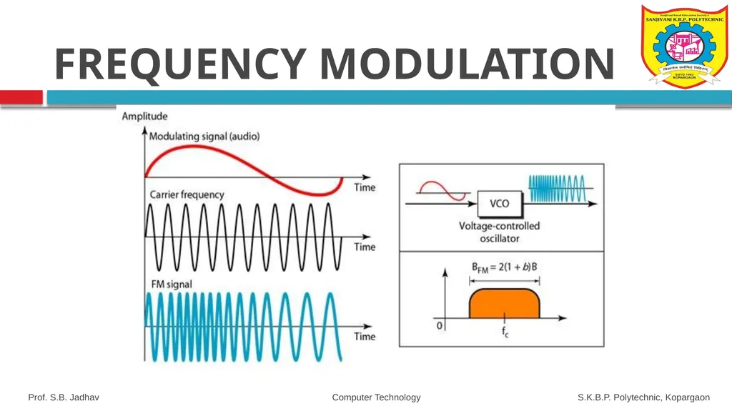
slide104. FREQUENCY MODULATION The modulation in which the frequency of the carrier wave is varied according to the instantaneous amplitude of the modulating signal keeping phase and amplitude as constant.
FM is normally implemented by using a voltage-controlled oscillator as with FSK. The frequency of the oscillator changes according to the input voltage which is the amplitude of the modulating signal. Prof. S.B. Jadhav Computer Technology S.K.B.P. Polytechnic, Kopargaon<br>
slide105. Prof. S.B. Jadhav Computer Technology S.K.B.P. Polytechnic, Kopargaon FREQUENCY MODULATION<br>
slide106. Prof. S.B. Jadhav Computer Technology S.K.B.P. Polytechnic, Kopargaon FREQUENCY MODULATION<br>
slide107. FM Advantage:
Modulation and demodulation does not catch any channel noise.
Low Power is required to transmit
All transmitted power is useful.
FM Disadvantage:
Circuit needed for FM modulation and demodulation is bit complicated than AM.
Large Bandwidth is required.
Application:
FM radio broad cast is an example Prof. S.B. Jadhav Computer Technology S.K.B.P. Polytechnic, Kopargaon FREQUENCY MODULATION<br>
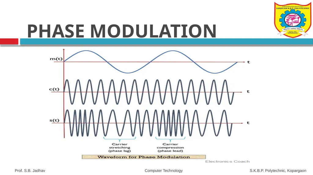
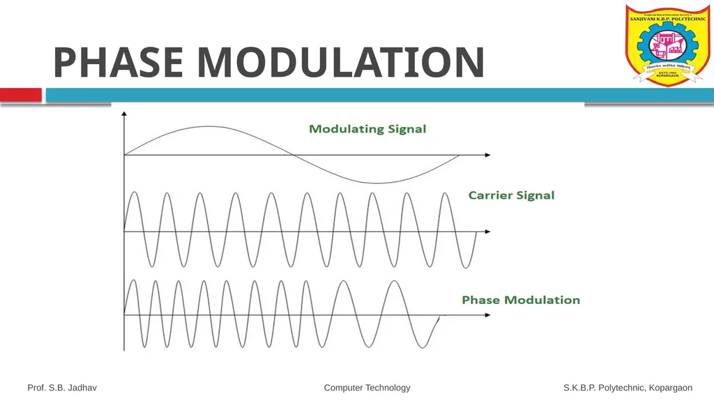
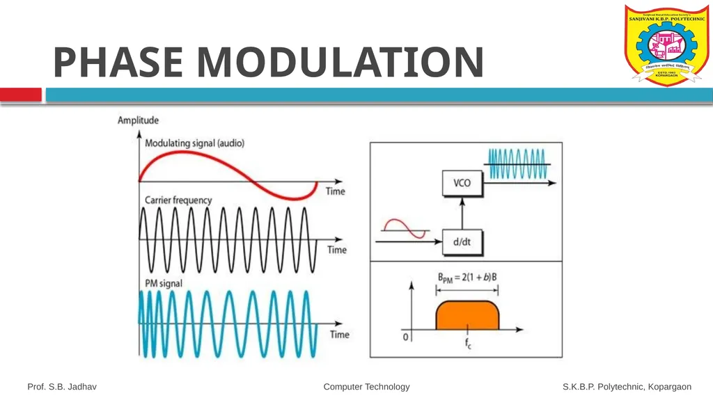
slide108. PHASE MODULATION The modulation in which the phase of the carrier wave is varied according to the instantaneous amplitude of the modulating signal keeping amplitude and frequency as constant.
Phase modulation is practically similar to Frequency Modulation, but in Phase modulation frequency of the carrier signal is not increased.
It is normally implemented by using a voltage-controlled oscillator along with a derivative.
The frequency of the oscillator changes according to the derivative of the input voltage which is the amplitude of the modulating signal. Prof. S.B. Jadhav Computer Technology S.K.B.P. Polytechnic, Kopargaon<br>
slide109. Prof. S.B. Jadhav Computer Technology S.K.B.P. Polytechnic, Kopargaon PHASE MODULATION<br>
slide110. Prof. S.B. Jadhav Computer Technology S.K.B.P. Polytechnic, Kopargaon PHASE MODULATION<br>
slide111. Prof. S.B. Jadhav Computer Technology S.K.B.P. Polytechnic, Kopargaon PHASE MODULATION<br>
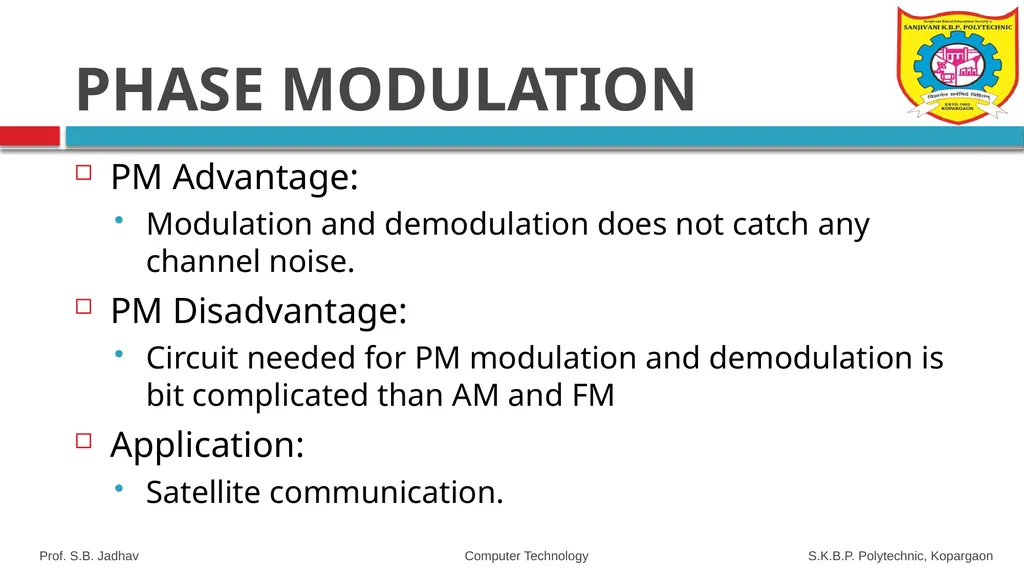
slide112. PM Advantage:
Modulation and demodulation does not catch any channel noise.
PM Disadvantage:
Circuit needed for PM modulation and demodulation is bit complicated than AM and FM
Application:
Satellite communication. Prof. S.B. Jadhav Computer Technology S.K.B.P. Polytechnic, Kopargaon PHASE MODULATION<br>
slide113. Home Work Compare the AM,FM, PM. Prof. S.B. Jadhav Computer Technology S.K.B.P. Polytechnic, Kopargaon<br>
slide114. Thank You Prof. S.B. Jadhav Computer Technology S.K.B.P. Polytechnic, Kopargaon<br>
With NBA ACCREDIATED programs , Approved by AICTE, New Delhi,
Recognized by Govt. of Maharashtra, Affiliated to Maharashtra State Board of Technical Education, Mumbai, ISO 9001:2015 Certified Institute Department:- Computer Technology Class:- SYcm-b Name of Subject:- Data Communication & computer network MSBTE Subject Code:- 22414<br>
slide2. Chapter-1
Marks-12 fundamentals of Data Communication & computer Network 22414<br>
slide4. Rationale Data Communication is the transmission of digital data through a network.
It is basis of computer networks.
Students of IT required to handle data communication related problems.
This subject enables to have insight into technology involved to make the network communication possible. Prof. S.B. Jadhav Computer Technology S.K.B.P. Polytechnic, Kopargaon<br>
slide5. Data Communications The term telecommunication means communication at a distance.
The word data refers to information presented in whatever form is agreed upon by the parties creating and using the data.
Data communication means the exchange of data between two devices via some form of transmission medium such as a wire cable. Prof. S.B. Jadhav Computer Technology S.K.B.P. Polytechnic, Kopargaon<br>
slide6. Fundamental Characteristics The effectiveness of a data communication system depend on four characteristics:
Delivery: correct Destination
Accuracy: Data must be accurately delivered
Timelines: Deliver data in timely manner
Jitter: Variation in packet arrival time. Prof. S.B. Jadhav Computer Technology S.K.B.P. Polytechnic, Kopargaon<br>
slide7. Components of Data Communication 1. Message 2. Sender 3. Receiver 4. Medium 5. Protocol Prof. S.B. Jadhav Computer Technology S.K.B.P. Polytechnic, Kopargaon<br>
slide8. Components of Data Communication Message- The message is the information (data) to be communicated. Popular forms of information include text, numbers, pictures, audio, and video.
Sender. The sender is the device that sends the data message. It can be a computer, workstation, telephone, video camera.
Receiver. The receiver is the device that receives the message. It can be a computer, workstation, telephone, television,& so on. Prof. S.B. Jadhav Computer Technology S.K.B.P. Polytechnic, Kopargaon<br>
slide9. Components of Data Communication Transmission medium. The transmission medium is the physical path by which a message travels from sender to receiver.
Examples of transmission media include twisted-pair, coaxial, fiber-optic, and radio waves.
Protocol. A protocol is a set of rules that govern data communications. It represents an agreement between the communicating devices. Without a protocol, two devices may be connected but not communicating, just as a person speaking French cannot be understood by a person who speaks only Japanese. Prof. S.B. Jadhav Computer Technology S.K.B.P. Polytechnic, Kopargaon<br>
slide10. Protocols and Standards Protocol is a set of rules that govern all aspect of data communication between computers on a network.
These rules include guidelines to regulate: access method, allowed physical topologies, types of cabling, and speed of data transfer.
A protocol defines what, how, when it communicated.
Protocols are to computers, what language is to humans. Since this article is in English, to understand it you must be able to read English. Similarly, for two devices on a network to successfully communicate, they must both understand the same protocols. Prof. S.B. Jadhav Computer Technology S.K.B.P. Polytechnic, Kopargaon<br>
slide11. Elements of a Protocol The key elements of a protocol are syntax, semantics and timing. Syntax :The structure or format of the data.
Eg. A simple protocol; 64 bits 8 bits 8 bits Sender address Receiver address data Prof. S.B. Jadhav Computer Technology S.K.B.P. Polytechnic, Kopargaon<br>
slide12. Elements of a Protocol ii) Semantics
Refers to the meaning of each section of bits.
how is a particular pattern to be interpreted, and what action is to be taken based on that interpretation.
Eg. Does an address identify the route to be taken or the final destination of the message?
For example => last 2 bits of receiver address containing 00=> S and R are on same N/W Prof. S.B. Jadhav Computer Technology S.K.B.P. Polytechnic, Kopargaon<br>
slide13. Elements of a Protocol iii) Timing
Refers to two characteristics:
When data to be sent
How fast it can be sent
Eg. If a sender produces data at 100 Mbps but the receiver can process data at only 1 Mbps, the transmission will overload the receiver and data will be largely lost.
sol:sender must send 1Mbps data and wait for ack before next 1Mbps of data. Prof. S.B. Jadhav Computer Technology S.K.B.P. Polytechnic, Kopargaon<br>
slide14. 1.2 Standards and Standards Organization<br>
slide15. Standards Standards are essential in creating and maintaining an open and competitive market for equipment manufacturers and in guaranteeing national and international interoperability of data and telecommunications technology and processes.
Standards provide guidelines to manufacturers, vendors, government agencies to ensure the interconnectivity.
Footnote:
If standards not followed by manufacturer then his goods will become incompatible with other manufacturers. Prof. S.B. Jadhav Computer Technology S.K.B.P. Polytechnic, Kopargaon<br>
slide16. Standards Data communication standards fall into two categories: de facto (meaning "by fact" or "by convention") and de jure (meaning "by law" or "by regulation").
De-facto. Standards that have not been approved by an organized body but have been adopted as standards through widespread use are de facto standards. De facto standards are often established originally by manufacturers who seek to define the functionality of a new product or technology.
De-jure. Those standards that have been legislated by an officially recognized body are de-jure standards. Prof. S.B. Jadhav Computer Technology S.K.B.P. Polytechnic, Kopargaon<br>
slide17. Standards & Standards Organization Standards are developed by cooperation among standards creation committees, forums, and government regulatory agencies.
Standards Creation Committees
International Standards Organization (ISO)
International Telecommunications Union (ITU)
American National Standards Institute (ANSI)
Institute of Electrical and Electronics Engineers (IEEE)
Electronic Industries Association (EIA)
Internet Engineering Task Force (IETF) Prof. S.B. Jadhav Computer Technology S.K.B.P. Polytechnic, Kopargaon<br>
slide18. a) International Standards Organization (ISO) A multinational body whose membership is drawn mainly from the standards creation committees of various governments throughout the world
Dedicated to worldwide agreement on international standards in a variety of fields.
Currently includes 82 memberships industrialized nations.
Aims to facilitate the international exchange of goods and services by providing models for compatibility, improved quality, increased productivity and decreased prices. Prof. S.B. Jadhav Computer Technology S.K.B.P. Polytechnic, Kopargaon<br>
slide19. Also known as International Telecommunications Union-Telecommunication Standards Sector (ITU-T)
An international standards organization related to the United Nations that develops standards for telecommunications.
Two popular standards developed by ITU-T are:
i) V.32 series – transmission over phone lines
ii) X.25 series – transmission over public digital networks, email and directory services and ISDN., X.400 Email, X.500 Directory services
ISDN- Integrated Digital Services Network b) International Telecommunications Union (ITU) Prof. S.B. Jadhav Computer Technology S.K.B.P. Polytechnic, Kopargaon<br>
slide20. c) American National Standards Institute (ANSI) A non-profit corporation not affiliated with US government.
ANSI members include professional societies, industry associations, governmental and regulatory bodies, and consumer groups.
Discussing the internetwork planning and engineering, ISDN services, signaling, and architecture and optical hierarchy. Prof. S.B. Jadhav Computer Technology S.K.B.P. Polytechnic, Kopargaon<br>
slide21. The largest national professional group involved in developing standards for computing, communication, electrical engineering, and electronics.
Aims to advance theory, creativity and product quality in the fields of electrical engineering, electronics and radio.
It sponsored an important standard for local area networks called Project 802 (eg. 802.3, 802.4 and 802.5 standards.) d) Institute of Electrical and Electronics Engineers (IEEE) Prof. S.B. Jadhav Computer Technology S.K.B.P. Polytechnic, Kopargaon<br>
slide22. e) Electronic Industries Association (EIA) An association of electronics manufacturers in the US.
Provide activities include public awareness education and lobbying efforts in addition to standards development.
Responsible for developing the EIA-232-D and EIA-530 standards. Prof. S.B. Jadhav Computer Technology S.K.B.P. Polytechnic, Kopargaon<br>
slide23. f) Internet Engineering Task Force (IETF) Concerned with speeding the growth and evolution of Internet communications.
The standards body for the Internet itself
Reviews internet software and hardware. Prof. S.B. Jadhav Computer Technology S.K.B.P. Polytechnic, Kopargaon<br>
slide24. Internet Standards An Internet standard is a thoroughly tested specification that is useful to and adhered to by those who work with the Internet. It is a formalized regulation that must be followed.
There is a strict procedure by which a specification attains Internet standard status.
A specification begins as an Internet draft. An Internet draft is a working document (a work in progress) with no official status and a 6-month lifetime. Upon recommendation from the Internet authorities, a draft may be published as a Request for Comment (RFC). Each RFC is edited, assigned a number, and made available to all interested parties. RFCs go through maturity levels and are categorized according to their requirement level. Prof. S.B. Jadhav Computer Technology S.K.B.P. Polytechnic, Kopargaon<br>
slide25. Bandwidth, Data Transmission Rate, Baud Rate & Bits Per Second<br>
slide26. Bandwidth Bandwidth is also called as data transfer rate.
Moving data from one point to another, in a given time period (usually a second), is called bandwidth.
Bandwidth is indicated by bits (of data) per second (bps). Prof. S.B. Jadhav Computer Technology S.K.B.P. Polytechnic, Kopargaon<br>
slide27. Bandwidth of Signal Bandwidth is defined as the portion of electromagnetic spectrum occupied by a signal.
Bandwidth is the difference between the upper and lower frequency limits of signal.
Example:
Voice signal ranges from 20Hz to 20KHz,
BW=f2-f1=20000-20=19980Hz Prof. S.B. Jadhav Computer Technology S.K.B.P. Polytechnic, Kopargaon<br>
slide28. Channel Bandwidth Bandwidth of a channel is defined as maximum frequency it can allow to pass through it without attenuation and distortion.
Digital Bandwidth: the maximum bit rate that a medium can propagate through it.
For digital devices, An Internet connection via cable modem may provide 25 Mbps of bandwidth.
For analog devices, the bandwidth is expressed in cycles per second, or Hertz (Hz)<br>
slide29. Bit Rate The speed of the data is expressed in bits per second (bits/s or bps).
The data rate R is a function of the duration of the bit or bit time (TB):
R = 1/TB
Rate is also called channel capacity C. If the bit time is 10ns, the data rate equals:
R = 1/10 x 109 = 100 million bits/s .
This is usually expressed as 100 Mbits/s. Prof. S.B. Jadhav Computer Technology S.K.B.P. Polytechnic, Kopargaon<br>
slide30. The bit rate is the number of bits sent in one second, usually expressed in bits per second (bps).
For example, kilobits per second (Kbps), Megabits per second (Mbps), Gigabits per second (Gbps), etc. Bit Rate<br>
slide31. Baud Rate The term “baud” originates from the French engineer Emile Baudot, who invented the 5-bit teletype code.
Baud rate refers to the number of signal or symbol changes that occur per second.
A symbol is one of several voltage, frequency, or phase changes.<br>
slide32. Baud Rate Binary has two symbols, one for each bit 0 or 1, that represent voltage levels.
In this case, the baud or symbol rate is the same as the bit rate.
However, it’s possible to have more than two symbols per transmission interval, whereby each symbol represents multiple bits.
For example, 1500 baud rate illustrates that the channel state can alter upto 1500 times per second. The meaning of changing state means that channel can change its state from 0 to 1 or from 1 to 0 up to 1500 times per second.<br>
slide33. Bit Rate & Baud Rate bit: a unit of information
baud: a unit of signalling speed.
Bit rate:b
Number of bits transmitted per second.
Baud Rate:s
Number of symbols transmitted per second.
General formula:
b=s*n
Where n is number of bits per symbol. Prof. S.B. Jadhav Computer Technology S.K.B.P. Polytechnic, Kopargaon<br>
slide34. Bit & Baud Prof. S.B. Jadhav Computer Technology S.K.B.P. Polytechnic, Kopargaon<br>
slide35. Bit Rate Vs Baud Rate<br>
slide36. A signal carries five bits in each signal element. If 1600 signal elements are sent per second, find the baud rate and bit rate in kbps. Baud rate is number of signal elements per second.
Bit rate is the number of bits per second.
We also know that S=N/r where S is the baud rate, N is the bit rate and r is the bits in each signal element.
In this case 1600 signal elements are sent per second.
So baud rate is 1600.
Now S=1600,r=5 and N is unknown.
So N=S*r=1600*5=8000 bps or 8 kbps.
Therefore the bit rate is 8kbps. Prof. S.B. Jadhav Computer Technology S.K.B.P. Polytechnic, Kopargaon<br>
slide37. Solve the problem What is the bit rate for the signal in the following figure?
Solution
No. of bits = 8, Bit Duration = 16 ns Bit Rate = 8/16 ns = 0.5 X 10⁹ bps = 500 Mbps Prof. S.B. Jadhav Computer Technology S.K.B.P. Polytechnic, Kopargaon<br>
slide38. Example An analog signal carries 4 bits per signal element. If 1000 signal elements are transmitted per second, find the bit rate.
Solution:
r = 4 S = 1000 N = S x r = 4000 bps Prof. S.B. Jadhav Computer Technology S.K.B.P. Polytechnic, Kopargaon<br>
slide39. Example An analog signal has a bit rate of 8000 bps and a baud rate of 1000 baud. How many data elements are carried by each signal element ?
Solution:
N = 8000
S = 1000
r = (N ÷ S) = 8 Prof. S.B. Jadhav Computer Technology S.K.B.P. Polytechnic, Kopargaon<br>
slide40. Modes of Communication<br>
slide41. Modes of Communication Communication between two devices ie sender and receiver can be of three types:
Simplex
Half-Duplex
Full-Duplex Prof. S.B. Jadhav Computer Technology S.K.B.P. Polytechnic, Kopargaon<br>
slide42. Simplex In simplex mode, the communication is unidirectional.
Only one of the devices on a link can transmit, the other can only receive.
e.g. keyboards, monitors, etc. Prof. S.B. Jadhav Computer Technology S.K.B.P. Polytechnic, Kopargaon<br>
slide43. Half-duplex In this mode, each station can both transmit and receive, but not at the same time.
When one device is sending, the other can only receive, and vice-versa.
e.g. walkie-talkies, CB(citizens band) etc. Prof. S.B. Jadhav Computer Technology S.K.B.P. Polytechnic, Kopargaon<br>
slide44. Full Duplex In full duplex mode, both stations can transmit and receive simultaneously.
One common example of full duplex is the Telephone network.
When two people are communicating by a telephone line, both can talk and listen at the same time. Prof. S.B. Jadhav Computer Technology S.K.B.P. Polytechnic, Kopargaon<br>
slide45. Direction of data flow Simplex Half Duplex Full Duplex Prof. S.B. Jadhav Computer Technology S.K.B.P. Polytechnic, Kopargaon<br>
slide46. Analog and Digital Signal<br>
slide47. Signals Signal: Information converted to electrical form which is suitable for transmission. Prof. S.B. Jadhav Computer Technology S.K.B.P. Polytechnic, Kopargaon<br>
slide48. Analog Signal An analog signal are continuous and passes through or includes an infinite number of continuous values along its path.
Analog signal is a continuous signal, in which, one time-varying quantity represents another time-based variable.
Sine wave is fundamental form of periodic analog signal.
These kind of signals works with physical values and natural phenomena such as earthquake, frequency, volcano, speed of wind, weight, lighting, etc. Prof. S.B. Jadhav Computer Technology S.K.B.P. Polytechnic, Kopargaon<br>
slide49. Characteristics Of Analog Signal These type of electronic signals are time-varying
Minimum and maximum values which is either positive or negative.
It can be either periodic or non-periodic.
Analog Signal works on continuous data.
The accuracy of the analog signal is not high when compared to the digital signal.
It helps you to measure natural or physical values.
Analog signal output form is like Curve, Line, or Graph, so it may not be meaningful to all.<br>
slide50. Advantages of Analog Signals Easier in processing
Best suited for audio and video transmission.
It has a low cost and is portable.
It has a much higher density so that it can present more refined information.
Not necessary to buy a new graphics board.
Uses less bandwidth than digital sounds
It is the natural form of a sound.<br>
slide51. Disadvantages of Analog Signals Analog tends to have a lower quality signal than digital.
The cables are sensitive to external influences.
The cost of the Analog wire is high and not easily portable.
Low availability of models with digital interfaces.
It offers limitations in editing
Quality is easily lost<br>
slide52. Digital Signal A digital signal can have only a limited number of defined values.
Although each value can be any number, it is as simple as 1 and 0.
All binary signals are digital, but all digital signals are not necessarily binary.
A digital signal is a signal that is used to represent data as a sequence of separate values at any point in time. It can only take on one of a fixed number of values. This type of signal represents a real number within a constant range of values. Prof. S.B. Jadhav Computer Technology S.K.B.P. Polytechnic, Kopargaon<br>
slide53. Characteristics of Digital Signals Digital signals can be processed and transmitted better compared to analog signal.
Digital signals are versatile, so it is widely used.
The accuracy of the digital signal is better than that of the analog signal.<br>
slide54. Advantages of Digital Signal Digital signals are more secure, and they do not get damaged by noise.
These signals use low bandwidth
They allow the signals transmitted over a lengthy distance.
Digital signal has a higher rate transmission
By using these signals, we can translate the messages, audio, video into device language. Prof. S.B. Jadhav Computer Technology S.K.B.P. Polytechnic, Kopargaon<br>
slide55. Disadvantage of Digital Signals Sampling may cause loss of information.
A/D and D/A demands mixed-signal hardware
Processor speed is limited
Develop quantization and round-off errors
It requires greater bandwidth
Systems and processing is more complex.<br>
slide57. Periodic and Non-periodic signals A signal is periodic signal if it completes a pattern within measurable time frame.
A periodic signal is characterised by amplitude, frequency and phase.
Mathematically: v(t)=V sin(2πft+θ)
V:Peak Amplitude
F:frequency
t:Time(seconds)
θ:Phase(degree or radians) Prof. S.B. Jadhav Computer Technology S.K.B.P. Polytechnic, Kopargaon<br>
slide58. Amplitude is the highest height of the signal, maximum value or strength of the signal over time; typically, this value is measured in volts.
frequency is the rate [in cycles per second, or Hertz (Hz)] at which the signal repeats., and
Phase is a measure of the relative position in time within a single period of a signal
An analog signal is not resistant toward the noise, therefore; it faces distortion as well as reduces the transmission quality. Prof. S.B. Jadhav Computer Technology S.K.B.P. Polytechnic, Kopargaon<br>
slide59. Effect of varying each of the three parameters Prof. S.B. Jadhav Computer Technology S.K.B.P. Polytechnic, Kopargaon<br>
slide60. Prof. S.B. Jadhav Computer Technology S.K.B.P. Polytechnic, Kopargaon<br>
slide61. Non Periodic Signal A signal that does not repeats its pattern over a period is called aperiodic signal or non periodic.
Both the Analog and Digital can be periodic or aperiodic: but in data communication periodic analog signals and aperiodic digital signals are used. Prof. S.B. Jadhav Computer Technology S.K.B.P. Polytechnic, Kopargaon<br>
slide63. Analog and Digital data Analog data take on continuous values in time interval.
For example, voice and video are continuously varying patterns of intensity. Most data collected by sensors, such as temperature and pressure, are continuous valued.
The most familiar example of analog data is audio, which, in the form of acoustic sound waves, can be perceived directly by human beings.
Digital data take on discrete values; examples are text and integers.
They cannot be easily stored or transmitted by data processing and communications systems in character form.
Morse code, International Reference Alphabet (IRA) are used to translate text into binary.<br>
slide64. Analog Transmission
Digital Transmission Prof. S.B. Jadhav Computer Technology S.K.B.P. Polytechnic, Kopargaon<br>
slide65. Analog transmission Analog transmission: is a means of transmitting analog signals without regard to their content; the signals may represent analog data (e.g., voice) or digital data.
In either case, the analog signal will become weaker (attenuate) after a certain distance.
To achieve longer distances, the analog transmission system includes amplifiers that boost the energy in the signal.
Unfortunately, the amplifier also boosts the noise components. Prof. S.B. Jadhav Computer Technology S.K.B.P. Polytechnic, Kopargaon<br>
slide66. Analog Transmission Prof. S.B. Jadhav Computer Technology S.K.B.P. Polytechnic, Kopargaon<br>
slide67. Digital transmission Digital transmission: is the transfer of data (a digital bitstream or a digitized analog signal) over a point-to-point or point-to-multipoint communication channel.
Examples of such channels are copper wires, optical fibers, wireless communication channels, storage media and computer buses.
The data are represented as an electromagnetic signal, such as an electrical voltage, radiowave, microwave, or infrared signal.
A digital signal can be transmitted only a limited distance before attenuation. Prof. S.B. Jadhav Computer Technology S.K.B.P. Polytechnic, Kopargaon<br>
slide68. Digital Transmission Prof. S.B. Jadhav Computer Technology S.K.B.P. Polytechnic, Kopargaon<br>
slide69. Prof. S.B. Jadhav Computer Technology S.K.B.P. Polytechnic, Kopargaon<br>
slide70. Both analog and digital information can be encoded as either analog or digital signals.
The particular encoding that is chosen depends on the specific requirements to be met and the media and communications facilities available. Prof. S.B. Jadhav Computer Technology S.K.B.P. Polytechnic, Kopargaon Signal Conversion<br>
slide71. Digital data, digital signals:
The simplest form of digital encoding of digital data is to assign one voltage level to binary one and another to binary zero.
More complex encoding schemes are used to improve performance, by altering the spectrum of the signal.
Digital data, analog signal:
A modem converts digital data to an analog signal so that it can be transmitted over an analog line.
The basic techniques are amplitude shift keying (ASK), frequency shift keying (FSK), and phase shift keying (PSK).
All involve altering one or more characteristics of a carrier frequency to represent binary data. Prof. S.B. Jadhav Computer Technology S.K.B.P. Polytechnic, Kopargaon Encoding and Modulation Techniques<br>
slide72. Analog data, digital signals:
Analog data, such as voice and video, are often digitized to be able to use digital transmission facilities.
The simplest technique is pulse code modulation (PCM), which involves sampling the analog data.
Analog data, analog signals:
Analog data are modulated by a carrier frequency to produce an analog signal, which can be utilized on an analog transmission system.
The basic techniques are amplitude modulation (AM), frequency modulation(FM), and phase modulation (PM). Prof. S.B. Jadhav Computer Technology S.K.B.P. Polytechnic, Kopargaon Encoding and Modulation Techniques<br>
slide73. Signal Conversion Prof. S.B. Jadhav Computer Technology S.K.B.P. Polytechnic, Kopargaon<br>
slide74. Digital to Analog Communication This method is used to send computer information over transmission channels that require analog signals, like a fiber optic networks, computer modems, cellular phone networks, and satellite systems.
In each of this systems, an electromagnetic carrier wave is used to carry the information over great distances and connect digital information users at remote locations.
The digital data is used to modulate one or more of the parameters of the carrier wave, This basic process is given the name "shift-keying“ (On-Off ) to differentiate it from the purely analog systems like AM and FM.<br>
slide75. Digital to Analog Conversion The case of transmitting digital data using analog signals.
The most familiar use is transmitting digital data through the public telephone network.
The telephone network was designed to receive, switch, and transmit analog signals in the voice-frequency range of about 300 to 3400 Hz.
Thus digital devices are attached to the network via a modem (modulator-demodulator), which converts digital data to analog signals, and vice versa. Prof. S.B. Jadhav Computer Technology S.K.B.P. Polytechnic, Kopargaon<br>
slide76. Digital to Analog Digital-to-analog conversion is the process of changing one of the characteristics of an analog signal based on the information in digital data.
A sine wave is defined by three characteristics: amplitude, frequency, and phase.
When we change anyone of these characteristics, we create a different version of that wave.
So, by changing one characteristic of a simple electric signal, we can use it to represent digital data Prof. S.B. Jadhav Computer Technology S.K.B.P. Polytechnic, Kopargaon<br>
slide77. Modulation or Encoding Modulation involves operation on one or more of the three characteristics of a carrier signal: amplitude, frequency, and phase.
Accordingly, there are three basic encoding or modulation techniques for transforming digital data into Analog signals:
Amplitude Shift Keying (ASK),
Frequency Shift Keying (FSK), and
Phase Shift Keying (PSK). Prof. S.B. Jadhav Computer Technology S.K.B.P. Polytechnic, Kopargaon<br>
slide78. Amplitude Shift Keying ASK is the digital carrier Modulation in which amplitude of carrier will take one of the two values in response to 0 or 1 value of digital data.
Amplitude Shift Keying (ASK) is a type of Amplitude Modulation which represents the binary data in the form of variations in the amplitude of a signal.
Any modulated signal has a high frequency carrier. The binary signal when ASK modulated, gives a zero value for Low input while it gives the carrier output for High input. Prof. S.B. Jadhav Computer Technology S.K.B.P. Polytechnic, Kopargaon<br>
slide79. In ASK, only the amplitude of the carrier signal is modified in modulation.
The simplest version is on–off keying (OOK).
In OOK, either bursts of a carrier wave are transmitted or nothing is transmitted depending whether the input message signal is 1 or 0.
Other versions of ASK use differing (non-zero) amplitudes to represent 1 and 0. Amplitude Shift Keying<br>
slide80. ASK Waveforms Figure (c) and (d) are the modulated waveforms using two versions of ASK. Figure (a) shows a digital message signal using two voltage levels. One level represents 1 and the other represents 0. Figure (b). The unmodulated carrier Figure (c) uses OOK Figure (d) uses binary ASK, or BASK.<br>
slide81. Amplitude Shift Keying<br>
slide82. Prof. S.B. Jadhav Computer Technology S.K.B.P. Polytechnic, Kopargaon Amplitude Shift Keying<br>
slide83. ASK Modulator The ASK modulator block diagram comprises of the carrier signal generator, the binary sequence from the message signal and the band-limited filter. Following is the block diagram of the ASK Modulator. Prof. S.B. Jadhav Computer Technology S.K.B.P. Polytechnic, Kopargaon<br>
slide84. Frequency Shift Keying (FSK) Frequency Shift Keying (FSK) is the digital modulation technique in which the frequency of the carrier signal varies according to the digital signal changes. FSK is a scheme of frequency modulation.
The output of a FSK modulated wave is high-in-frequency for a binary High input and is low-in-frequency for a binary Low input. The binary 1s and 0s are called Mark and Space frequencies. Prof. S.B. Jadhav Computer Technology S.K.B.P. Polytechnic, Kopargaon<br>
slide85. Frequency Shift Keying(FSK) In FSK, frequency of sinusoidal carrier is shifted between two discrete values.
One of these frequencies (f1) represents a binary 1 and other frequency (f2) represents binary 0.
There is no change in amplitude of carrier.
It consists of voltage controlled oscillators (VCO) which produce sinewave at frequencies f1 and f0.
Corresponding to "binary 0 "input, the VCO produces a sinewave of
frequency f0 whereas corresponding to binary 1 input VCO produces
a sinewave of frequency f1.<br>
slide86. Frequency Shift Keying (FSK)<br>
slide87. FSK Modulator Circuit<br>
slide88. The following image is the diagrammatic representation of FSK modulated waveform along with its input. Prof. S.B. Jadhav Computer Technology S.K.B.P. Polytechnic, Kopargaon Frequency Shift Keying (FSK)<br>
slide89. Question: Draw a BFSK waveform to represent the following bit stream 0 11 0 1 0. Prof. S.B. Jadhav Computer Technology S.K.B.P. Polytechnic, Kopargaon Frequency Shift Keying (FSK) Question: Explain the process of FSK modulation with diagram.<br>
slide90. Phase Shift Keying (PSK) The phase of the carrier wave at the beginning of the pulse is changed between discrete values.
Phase-shift keying (PSK) is a digital to analog modulation scheme based on changing, or modulating, the initial phase of a carrier signal.
PSK is used to represent digital information, such as binary digits zero (0) and one (1).
The modulation of PSK is done using a balance modulator, which multiplies the two signals applied at the input. For a zero binary input, the phase will be 180° and for a high input, the phase reversal is of 0°.
PSK technique is widely used for wireless LANs, bio-metric, contactless operations, along with RFID and Bluetooth communications. Prof. S.B. Jadhav Computer Technology S.K.B.P. Polytechnic, Kopargaon<br>
slide91. Types of PSK PSK is of two types, depending upon the phases the signal gets shifted. They are
Binary Phase Shift Keying (BPSK)
This is also called as 2-phase PSK or Phase Reversal Keying. In this technique, the sine wave carrier takes two phase reversals such as 0° and 180°.
BPSK is basically a Double Side Band Suppressed Carrier (DSBSC) modulation scheme, for message being the digital information.
Quadrature Phase Shift Keying (QPSK)
This is the phase shift keying technique, in which the sine wave carrier takes four phase reversals such as 0°, 90°, 180°, and 270°.
If this kind of techniques are further extended, PSK can be done by eight or sixteen values also, depending upon the requirement. Prof. S.B. Jadhav Computer Technology S.K.B.P. Polytechnic, Kopargaon<br>
slide92. Phase Shift Keying<br>
slide93. PSK Modulator Circuit<br>
slide94. PSK Following is the diagrammatic representation of BPSK Modulated output wave along with its given input. Prof. S.B. Jadhav Computer Technology S.K.B.P. Polytechnic, Kopargaon<br>
slide95. Amplitude Shift Keying-Example Prof. S.B. Jadhav Computer Technology S.K.B.P. Polytechnic, Kopargaon<br>
slide96. Frequency Shift Keying-Example Prof. S.B. Jadhav Computer Technology S.K.B.P. Polytechnic, Kopargaon<br>
slide97. Phase Shift Keying-Example Prof. S.B. Jadhav Computer Technology S.K.B.P. Polytechnic, Kopargaon<br>
slide98. Prof. S.B. Jadhav Computer Technology S.K.B.P. Polytechnic, Kopargaon<br>
slide99. Analog to Analog Conversion Analog-to-analog conversion, or modulation, is the representation of analog information by an analog signal.
It is a process by which a characteristic of carrier wave is varied according to the instantaneous amplitude of the modulating signal.
Analog to Analog conversion can be done in three ways:
Amplitude Modulation
Frequency Modulation
Phase Modulation Prof. S.B. Jadhav Computer Technology S.K.B.P. Polytechnic, Kopargaon<br>
slide100. AMPLITUDE MODULATION: The modulation in which the amplitude of the carrier wave is varied according to the instantaneous amplitude of the modulating signal keeping phase and frequency as constant.
AM is normally implemented by using a simple multiplier because the amplitude of the carrier signal needs to be changed according to the amplitude of the modulating signal.
AM bandwidth: The modulation creates a bandwidth that is twice the bandwidth of the modulating signal and covers a range centered on the carrier frequency. Bandwidth= 2fm Prof. S.B. Jadhav Computer Technology S.K.B.P. Polytechnic, Kopargaon<br>
slide101. Prof. S.B. Jadhav Computer Technology S.K.B.P. Polytechnic, Kopargaon AMPLITUDE MODULATION:<br>
slide102. Prof. S.B. Jadhav Computer Technology S.K.B.P. Polytechnic, Kopargaon AMPLITUDE MODULATION:<br>
slide103. Disadvantage:
AM is very susceptible to noise.
Power wastage takes place.
Application:
AM radio broad cast is an example Prof. S.B. Jadhav Computer Technology S.K.B.P. Polytechnic, Kopargaon<br>
slide104. FREQUENCY MODULATION The modulation in which the frequency of the carrier wave is varied according to the instantaneous amplitude of the modulating signal keeping phase and amplitude as constant.
FM is normally implemented by using a voltage-controlled oscillator as with FSK. The frequency of the oscillator changes according to the input voltage which is the amplitude of the modulating signal. Prof. S.B. Jadhav Computer Technology S.K.B.P. Polytechnic, Kopargaon<br>
slide105. Prof. S.B. Jadhav Computer Technology S.K.B.P. Polytechnic, Kopargaon FREQUENCY MODULATION<br>
slide106. Prof. S.B. Jadhav Computer Technology S.K.B.P. Polytechnic, Kopargaon FREQUENCY MODULATION<br>
slide107. FM Advantage:
Modulation and demodulation does not catch any channel noise.
Low Power is required to transmit
All transmitted power is useful.
FM Disadvantage:
Circuit needed for FM modulation and demodulation is bit complicated than AM.
Large Bandwidth is required.
Application:
FM radio broad cast is an example Prof. S.B. Jadhav Computer Technology S.K.B.P. Polytechnic, Kopargaon FREQUENCY MODULATION<br>
slide108. PHASE MODULATION The modulation in which the phase of the carrier wave is varied according to the instantaneous amplitude of the modulating signal keeping amplitude and frequency as constant.
Phase modulation is practically similar to Frequency Modulation, but in Phase modulation frequency of the carrier signal is not increased.
It is normally implemented by using a voltage-controlled oscillator along with a derivative.
The frequency of the oscillator changes according to the derivative of the input voltage which is the amplitude of the modulating signal. Prof. S.B. Jadhav Computer Technology S.K.B.P. Polytechnic, Kopargaon<br>
slide109. Prof. S.B. Jadhav Computer Technology S.K.B.P. Polytechnic, Kopargaon PHASE MODULATION<br>
slide110. Prof. S.B. Jadhav Computer Technology S.K.B.P. Polytechnic, Kopargaon PHASE MODULATION<br>
slide111. Prof. S.B. Jadhav Computer Technology S.K.B.P. Polytechnic, Kopargaon PHASE MODULATION<br>
slide112. PM Advantage:
Modulation and demodulation does not catch any channel noise.
PM Disadvantage:
Circuit needed for PM modulation and demodulation is bit complicated than AM and FM
Application:
Satellite communication. Prof. S.B. Jadhav Computer Technology S.K.B.P. Polytechnic, Kopargaon PHASE MODULATION<br>
slide113. Home Work Compare the AM,FM, PM. Prof. S.B. Jadhav Computer Technology S.K.B.P. Polytechnic, Kopargaon<br>
slide114. Thank You Prof. S.B. Jadhav Computer Technology S.K.B.P. Polytechnic, Kopargaon<br>