
Slice Energy Spread Measurements in the EuXFEL
SN
Published · 23 slides · 0 views

1 / 1



Description
Slice Energy Spread Measurements in the EuXFEL Injector Stuart Walker, Sergey Tomin, Igor Zagorodnov, Nina Golubeva, Matthias Scholz, Winfried Decking, Bolko Beutner, Erion Gjonaj LEDS Workshop 2024, Bern, 1992024 Overview Subheading,
Related Topics
Download this presentation From Below
"Slice Energy Spread Measurements in the EuXFEL" is the property of its rightful owner. Permission is granted to download and print the materials on this website for personal, non-commercial use only, and to display it on your personal computer provided you do not modify the materials and that you retain all copyright notices contained in the materials. By downloading content from our website, you accept the terms of this agreement.
Share
Embed code
Presentation Transcript
01
Slice Energy Spread Measurements in the EuXFEL Injector Stuart Walker, Sergey Tomin, Igor Zagorodnov, Nina Golubeva, Matthias Scholz, Winfried Decking, Bolko Beutner, Erion Gjonaj
LEDS Workshop 2024, Bern, 19/9/2024<br>
LEDS Workshop 2024, Bern, 19/9/2024<br>
02
Overview Subheading, optional Motivation
Context
Overview of the EuXFEL
Slice Energy Spread Measurements
Conclusion | Slice Energy Spread Measurements in the EuXFEL linac | Stuart Walker, LEDS Workshop, Bern, Switzerland, 19/09/2024<br>
Context
Overview of the EuXFEL
Slice Energy Spread Measurements
Conclusion | Slice Energy Spread Measurements in the EuXFEL linac | Stuart Walker, LEDS Workshop, Bern, Switzerland, 19/09/2024<br>
03
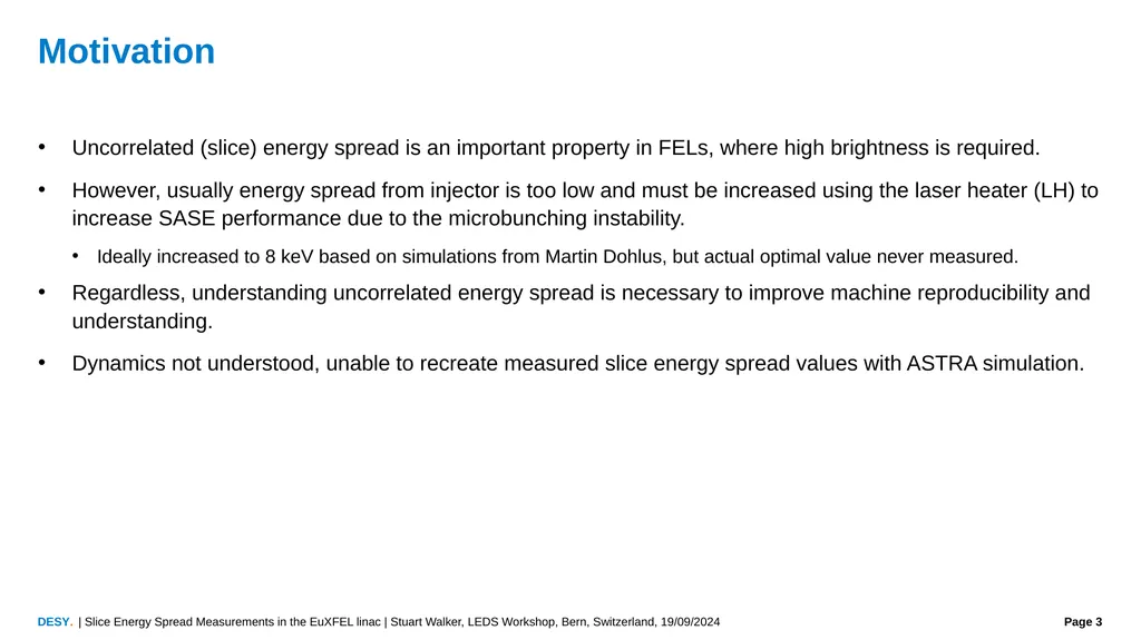
Motivation Uncorrelated (slice) energy spread is an important property in FELs, where high brightness is required.
However, usually energy spread from injector is too low and must be increased using the laser heater (LH) to increase SASE performance due to the microbunching instability.
Ideally increased to 8 keV based on simulations from Martin Dohlus, but actual optimal value never measured.
Regardless, understanding uncorrelated energy spread is necessary to improve machine reproducibility and understanding.
Dynamics not understood, unable to recreate measured slice energy spread values with ASTRA simulation. | Slice Energy Spread Measurements in the EuXFEL linac | Stuart Walker, LEDS Workshop, Bern, Switzerland, 19/09/2024<br>
However, usually energy spread from injector is too low and must be increased using the laser heater (LH) to increase SASE performance due to the microbunching instability.
Ideally increased to 8 keV based on simulations from Martin Dohlus, but actual optimal value never measured.
Regardless, understanding uncorrelated energy spread is necessary to improve machine reproducibility and understanding.
Dynamics not understood, unable to recreate measured slice energy spread values with ASTRA simulation. | Slice Energy Spread Measurements in the EuXFEL linac | Stuart Walker, LEDS Workshop, Bern, Switzerland, 19/09/2024<br>
04
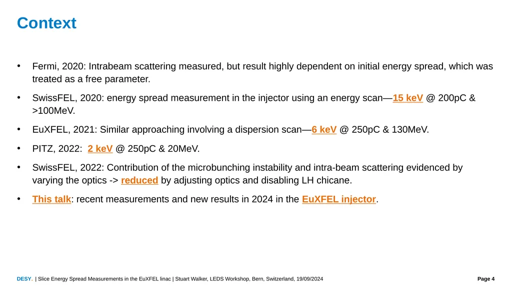
Context Fermi, 2020: Intrabeam scattering measured, but result highly dependent on initial energy spread, which was treated as a free parameter.
SwissFEL, 2020: energy spread measurement in the injector using an energy scan—15 keV @ 200pC & >100MeV.
EuXFEL, 2021: Similar approaching involving a dispersion scan—6 keV @ 250pC & 130MeV.
PITZ, 2022: 2 keV @ 250pC & 20MeV.
SwissFEL, 2022: Contribution of the microbunching instability and intra-beam scattering evidenced by varying the optics -> reduced by adjusting optics and disabling LH chicane.
This talk: recent measurements and new results in 2024 in the EuXFEL injector. | Slice Energy Spread Measurements in the EuXFEL linac | Stuart Walker, LEDS Workshop, Bern, Switzerland, 19/09/2024<br>
SwissFEL, 2020: energy spread measurement in the injector using an energy scan—15 keV @ 200pC & >100MeV.
EuXFEL, 2021: Similar approaching involving a dispersion scan—6 keV @ 250pC & 130MeV.
PITZ, 2022: 2 keV @ 250pC & 20MeV.
SwissFEL, 2022: Contribution of the microbunching instability and intra-beam scattering evidenced by varying the optics -> reduced by adjusting optics and disabling LH chicane.
This talk: recent measurements and new results in 2024 in the EuXFEL injector. | Slice Energy Spread Measurements in the EuXFEL linac | Stuart Walker, LEDS Workshop, Bern, Switzerland, 19/09/2024<br>
05
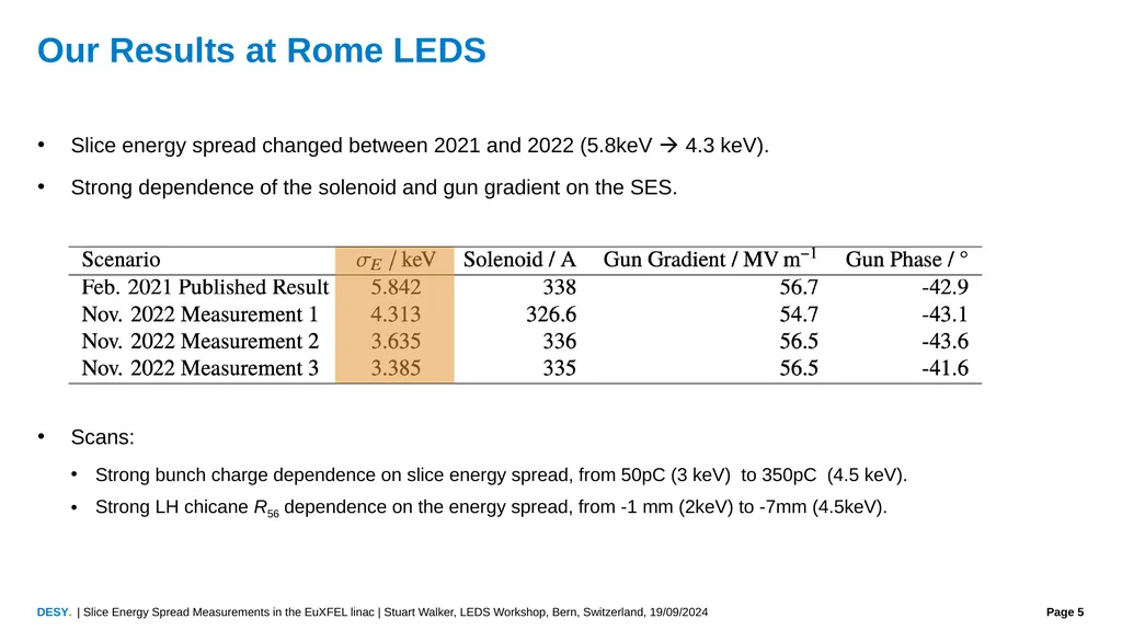
Our Results at Rome LEDS Slice energy spread changed between 2021 and 2022 (5.8keV 4.3 keV).
Strong dependence of the solenoid and gun gradient on the SES.
Scans:
Strong bunch charge dependence on slice energy spread, from 50pC (3 keV) to 350pC (4.5 keV).
Strong LH chicane R56 dependence on the energy spread, from -1 mm (2keV) to -7mm (4.5keV). | Slice Energy Spread Measurements in the EuXFEL linac | Stuart Walker, LEDS Workshop, Bern, Switzerland, 19/09/2024<br>
Strong dependence of the solenoid and gun gradient on the SES.
Scans:
Strong bunch charge dependence on slice energy spread, from 50pC (3 keV) to 350pC (4.5 keV).
Strong LH chicane R56 dependence on the energy spread, from -1 mm (2keV) to -7mm (4.5keV). | Slice Energy Spread Measurements in the EuXFEL linac | Stuart Walker, LEDS Workshop, Bern, Switzerland, 19/09/2024<br>
06
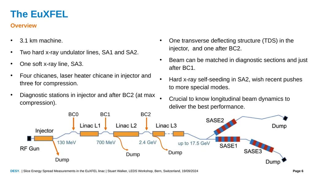
The EuXFEL Overview 3.1 km machine.
Two hard x-ray undulator lines, SA1 and SA2.
One soft x-ray line, SA3.
Four chicanes, laser heater chicane in injector and three for compression.
Diagnostic stations in injector and after BC2 (at max compression).
One transverse deflecting structure (TDS) in the injector, and one after BC2.
Beam can be matched in diagnostic sections and just after BC1.
Hard x-ray self-seeding in SA2, wish recent pushes to more special modes.
Crucial to know longitudinal beam dynamics to deliver the best performance. BC0 BC1 BC2 Dump Dump Dump | Slice Energy Spread Measurements in the EuXFEL linac | Stuart Walker, LEDS Workshop, Bern, Switzerland, 19/09/2024<br>
Two hard x-ray undulator lines, SA1 and SA2.
One soft x-ray line, SA3.
Four chicanes, laser heater chicane in injector and three for compression.
Diagnostic stations in injector and after BC2 (at max compression).
One transverse deflecting structure (TDS) in the injector, and one after BC2.
Beam can be matched in diagnostic sections and just after BC1.
Hard x-ray self-seeding in SA2, wish recent pushes to more special modes.
Crucial to know longitudinal beam dynamics to deliver the best performance. BC0 BC1 BC2 Dump Dump Dump | Slice Energy Spread Measurements in the EuXFEL linac | Stuart Walker, LEDS Workshop, Bern, Switzerland, 19/09/2024<br>
07
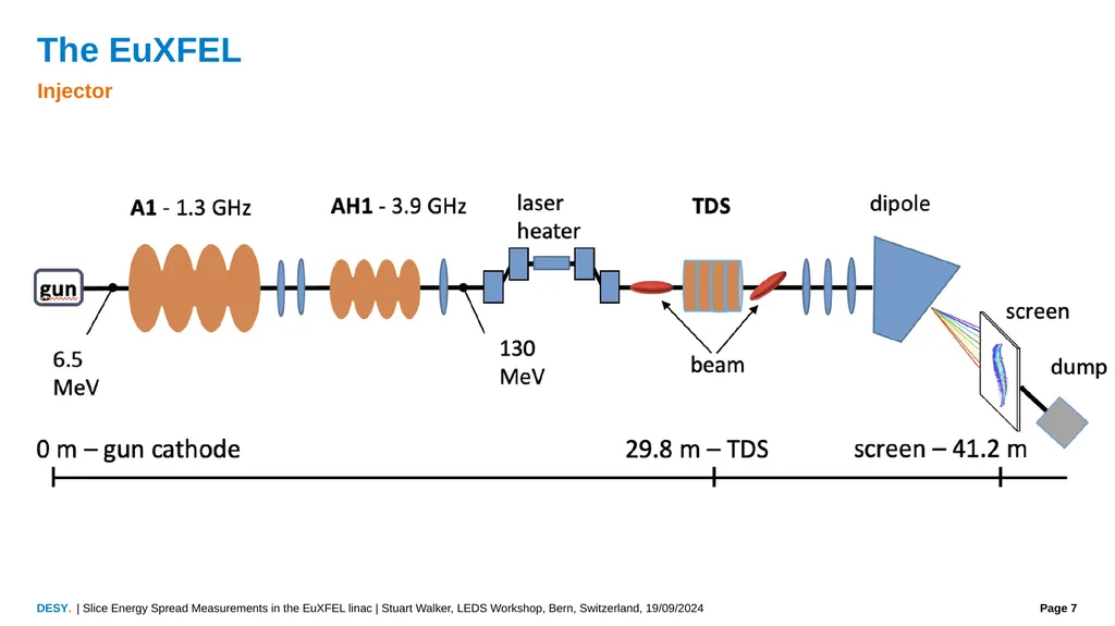
The EuXFEL Injector | Slice Energy Spread Measurements in the EuXFEL linac | Stuart Walker, LEDS Workshop, Bern, Switzerland, 19/09/2024<br>
08
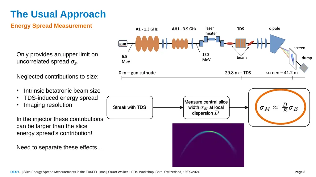
The Usual Approach Energy Spread Measurement Only provides an upper limit on uncorrelated spread σE.
Neglected contributions to size:
Intrinsic betatronic beam size
TDS-induced energy spread
Imaging resolution
In the injector these contributions can be larger than the slice energy spread's contribution!
Need to separate these effects... | Slice Energy Spread Measurements in the EuXFEL linac | Stuart Walker, LEDS Workshop, Bern, Switzerland, 19/09/2024<br>
Neglected contributions to size:
Intrinsic betatronic beam size
TDS-induced energy spread
Imaging resolution
In the injector these contributions can be larger than the slice energy spread's contribution!
Need to separate these effects... | Slice Energy Spread Measurements in the EuXFEL linac | Stuart Walker, LEDS Workshop, Bern, Switzerland, 19/09/2024<br>
09
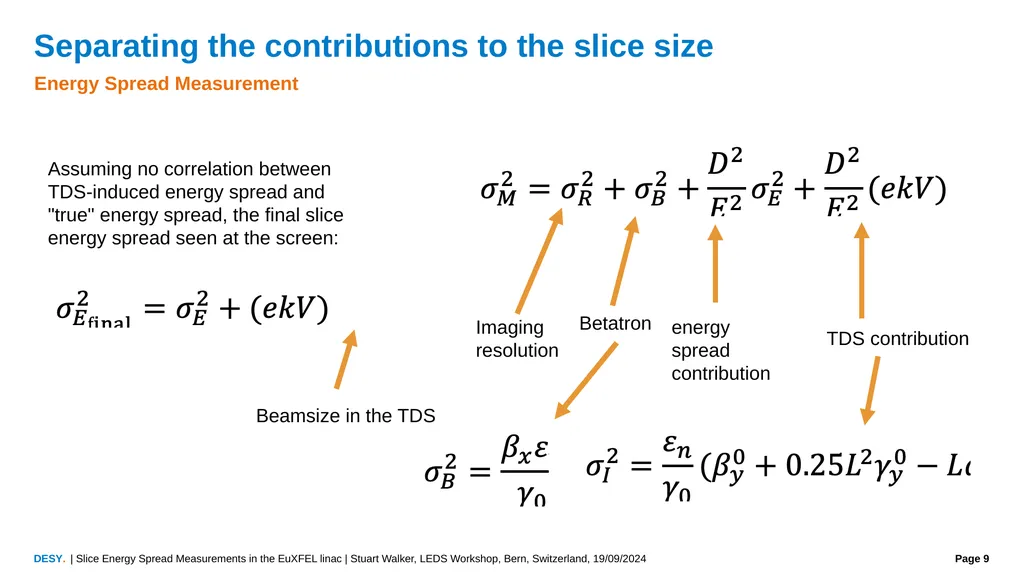
Separating the contributions to the slice size Energy Spread Measurement Assuming no correlation between TDS-induced energy spread and "true" energy spread, the final slice energy spread seen at the screen: | Slice Energy Spread Measurements in the EuXFEL linac | Stuart Walker, LEDS Workshop, Bern, Switzerland, 19/09/2024<br>
10
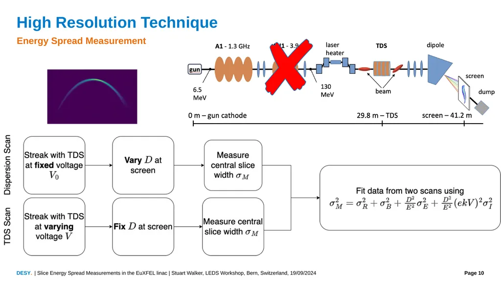
High Resolution Technique Energy Spread Measurement | Slice Energy Spread Measurements in the EuXFEL linac | Stuart Walker, LEDS Workshop, Bern, Switzerland, 19/09/2024<br>
11
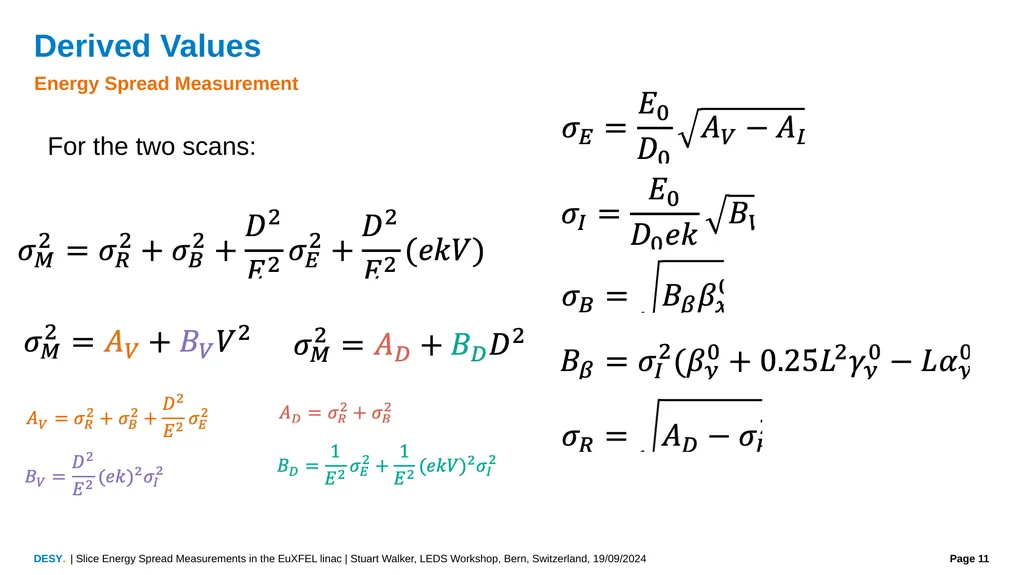
Derived Values Energy Spread Measurement For the two scans: | Slice Energy Spread Measurements in the EuXFEL linac | Stuart Walker, LEDS Workshop, Bern, Switzerland, 19/09/2024<br>
12
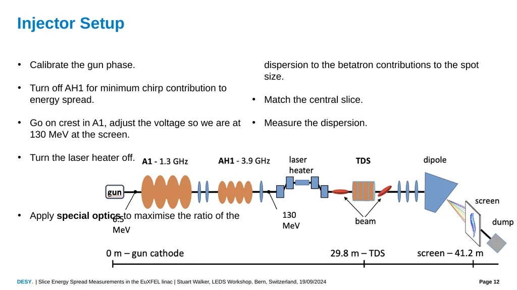
Injector Setup Calibrate the gun phase.
Turn off AH1 for minimum chirp contribution to energy spread.
Go on crest in A1, adjust the voltage so we are at 130 MeV at the screen.
Turn the laser heater off.
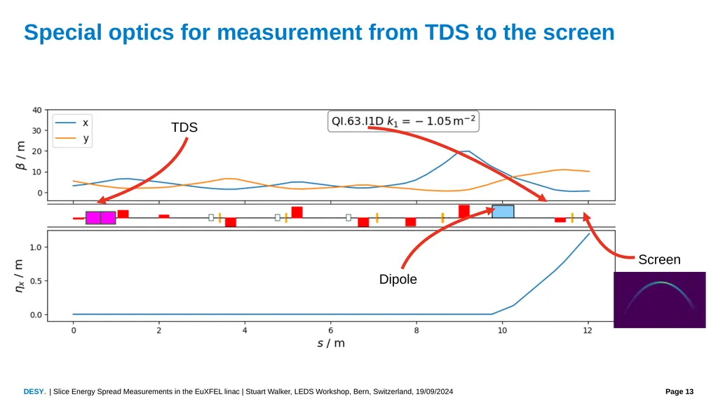
Apply special optics to maximise the ratio of the dispersion to the betatron contributions to the spot size.
Match the central slice.
Measure the dispersion. | Slice Energy Spread Measurements in the EuXFEL linac | Stuart Walker, LEDS Workshop, Bern, Switzerland, 19/09/2024<br>
Turn off AH1 for minimum chirp contribution to energy spread.
Go on crest in A1, adjust the voltage so we are at 130 MeV at the screen.
Turn the laser heater off.
Apply special optics to maximise the ratio of the dispersion to the betatron contributions to the spot size.
Match the central slice.
Measure the dispersion. | Slice Energy Spread Measurements in the EuXFEL linac | Stuart Walker, LEDS Workshop, Bern, Switzerland, 19/09/2024<br>
13
Special optics for measurement from TDS to the screen Screen TDS Dipole | Slice Energy Spread Measurements in the EuXFEL linac | Stuart Walker, LEDS Workshop, Bern, Switzerland, 19/09/2024<br>
14
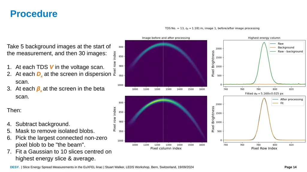
Procedure Take 5 background images at the start of the measurement, and then 30 images:
At each TDS V in the voltage scan.
At each Dx at the screen in dispersion scan.
At each βx at the screen in the beta scan.
Then:
Subtract background.
Mask to remove isolated blobs.
Pick the largest connected non-zero pixel blob to be "the beam".
Fit a Gaussian to 10 slices centred on highest energy slice & average. | Slice Energy Spread Measurements in the EuXFEL linac | Stuart Walker, LEDS Workshop, Bern, Switzerland, 19/09/2024<br>
At each TDS V in the voltage scan.
At each Dx at the screen in dispersion scan.
At each βx at the screen in the beta scan.
Then:
Subtract background.
Mask to remove isolated blobs.
Pick the largest connected non-zero pixel blob to be "the beam".
Fit a Gaussian to 10 slices centred on highest energy slice & average. | Slice Energy Spread Measurements in the EuXFEL linac | Stuart Walker, LEDS Workshop, Bern, Switzerland, 19/09/2024<br>
15
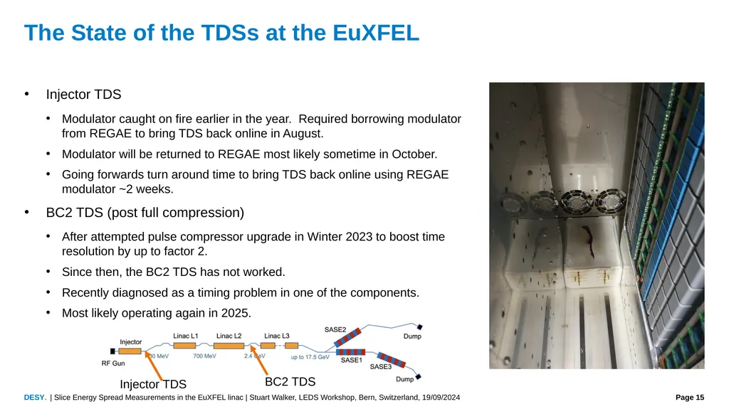
The State of the TDSs at the EuXFEL Injector TDS
Modulator caught on fire earlier in the year. Required borrowing modulator from REGAE to bring TDS back online in August.
Modulator will be returned to REGAE most likely sometime in October.
Going forwards turn around time to bring TDS back online using REGAE modulator ~2 weeks.
BC2 TDS (post full compression)
After attempted pulse compressor upgrade in Winter 2023 to boost time resolution by up to factor 2.
Since then, the BC2 TDS has not worked.
Recently diagnosed as a timing problem in one of the components.
Most likely operating again in 2025. BC2 TDS Injector TDS | Slice Energy Spread Measurements in the EuXFEL linac | Stuart Walker, LEDS Workshop, Bern, Switzerland, 19/09/2024<br>
Modulator caught on fire earlier in the year. Required borrowing modulator from REGAE to bring TDS back online in August.
Modulator will be returned to REGAE most likely sometime in October.
Going forwards turn around time to bring TDS back online using REGAE modulator ~2 weeks.
BC2 TDS (post full compression)
After attempted pulse compressor upgrade in Winter 2023 to boost time resolution by up to factor 2.
Since then, the BC2 TDS has not worked.
Recently diagnosed as a timing problem in one of the components.
Most likely operating again in 2025. BC2 TDS Injector TDS | Slice Energy Spread Measurements in the EuXFEL linac | Stuart Walker, LEDS Workshop, Bern, Switzerland, 19/09/2024<br>
16
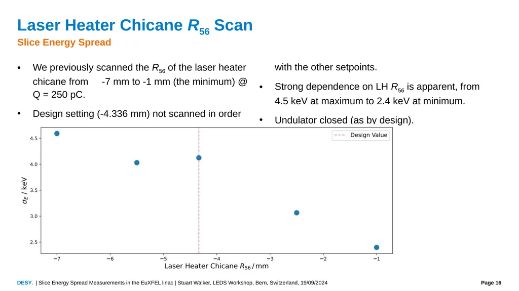
Laser Heater Chicane R56 Scan Slice Energy Spread We previously scanned the R56 of the laser heater chicane from -7 mm to -1 mm (the minimum) @ Q = 250 pC.
Design setting (-4.336 mm) not scanned in order with the other setpoints.
Strong dependence on LH R56 is apparent, from 4.5 keV at maximum to 2.4 keV at minimum.
Undulator closed (as by design). | Slice Energy Spread Measurements in the EuXFEL linac | Stuart Walker, LEDS Workshop, Bern, Switzerland, 19/09/2024<br>
Design setting (-4.336 mm) not scanned in order with the other setpoints.
Strong dependence on LH R56 is apparent, from 4.5 keV at maximum to 2.4 keV at minimum.
Undulator closed (as by design). | Slice Energy Spread Measurements in the EuXFEL linac | Stuart Walker, LEDS Workshop, Bern, Switzerland, 19/09/2024<br>
17
Laser Heater Chicane R56 Scan Slice Energy Spread Repeated the scan with the new laser and with the undulator open:
Remove any edge focusing from the undulator simpler experimental setup.
Weak dependence on the undulator shown: small differences can be explained as due to undulator edge focusing different optics IBS.
Laser choice impact negligible. | Slice Energy Spread Measurements in the EuXFEL linac | Stuart Walker, LEDS Workshop, Bern, Switzerland, 19/09/2024<br>
Remove any edge focusing from the undulator simpler experimental setup.
Weak dependence on the undulator shown: small differences can be explained as due to undulator edge focusing different optics IBS.
Laser choice impact negligible. | Slice Energy Spread Measurements in the EuXFEL linac | Stuart Walker, LEDS Workshop, Bern, Switzerland, 19/09/2024<br>
18
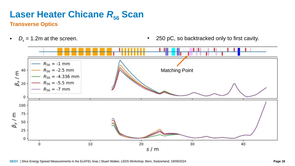
Laser Heater Chicane R56 Scan Transverse Optics Dx = 1.2m at the screen.
250 pC, so backtracked only to first cavity. Matching Point | Slice Energy Spread Measurements in the EuXFEL linac | Stuart Walker, LEDS Workshop, Bern, Switzerland, 19/09/2024<br>
250 pC, so backtracked only to first cavity. Matching Point | Slice Energy Spread Measurements in the EuXFEL linac | Stuart Walker, LEDS Workshop, Bern, Switzerland, 19/09/2024<br>
19
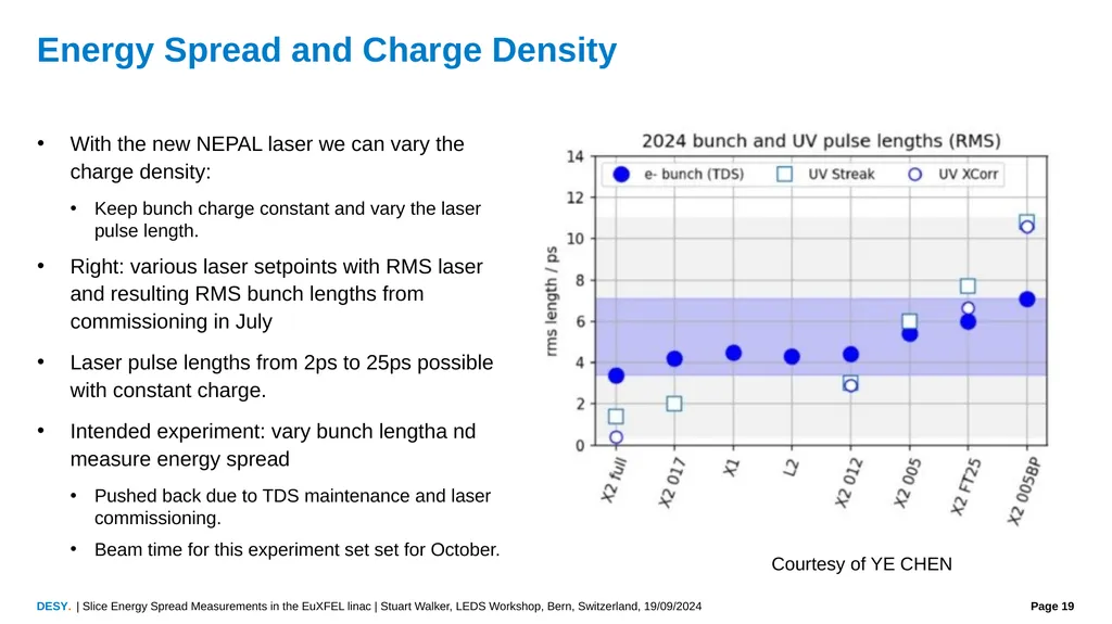
Energy Spread and Charge Density With the new NEPAL laser we can vary the charge density:
Keep bunch charge constant and vary the laser pulse length.
Right: various laser setpoints with RMS laser and resulting RMS bunch lengths from commissioning in July
Laser pulse lengths from 2ps to 25ps possible with constant charge.
Intended experiment: vary bunch lengtha nd measure energy spread
Pushed back due to TDS maintenance and laser commissioning.
Beam time for this experiment set set for October. Courtesy of YE CHEN | Slice Energy Spread Measurements in the EuXFEL linac | Stuart Walker, LEDS Workshop, Bern, Switzerland, 19/09/2024<br>
Keep bunch charge constant and vary the laser pulse length.
Right: various laser setpoints with RMS laser and resulting RMS bunch lengths from commissioning in July
Laser pulse lengths from 2ps to 25ps possible with constant charge.
Intended experiment: vary bunch lengtha nd measure energy spread
Pushed back due to TDS maintenance and laser commissioning.
Beam time for this experiment set set for October. Courtesy of YE CHEN | Slice Energy Spread Measurements in the EuXFEL linac | Stuart Walker, LEDS Workshop, Bern, Switzerland, 19/09/2024<br>
20
Conclusion We continue to investigate the physics of slice energy spread in the EuXFEL injector and linac.
We repeated our LH R56 scan measurement, replicating the strong dependence of the energy spread on the R56 independent of undulator setting and laser choice.
Needs to yet be understood. Typically one would imagine a multi-stage compression scheme to cause MBI.
However, we have only one, relatively weak, chicane in our measurement configuration.
Possible microbunching coming out of the gun?
Our longitudinal diagnostics in the linac have had a tough year
The injector TDS is now dependent on swapping in a modulator from a different accelerator as required.
BC2 TDS has been offline all year, but forecasted to be available again from January 2025.
Measurements planned for October:
Charge density scan (varying bunch length with constant charge).
Laser Heater absolute calibration.
Injector slice energy spread versus microbunching and energy spread in SA2.M | Slice Energy Spread Measurements in the EuXFEL linac | Stuart Walker, LEDS Workshop, Bern, Switzerland, 19/09/2024<br>
We repeated our LH R56 scan measurement, replicating the strong dependence of the energy spread on the R56 independent of undulator setting and laser choice.
Needs to yet be understood. Typically one would imagine a multi-stage compression scheme to cause MBI.
However, we have only one, relatively weak, chicane in our measurement configuration.
Possible microbunching coming out of the gun?
Our longitudinal diagnostics in the linac have had a tough year
The injector TDS is now dependent on swapping in a modulator from a different accelerator as required.
BC2 TDS has been offline all year, but forecasted to be available again from January 2025.
Measurements planned for October:
Charge density scan (varying bunch length with constant charge).
Laser Heater absolute calibration.
Injector slice energy spread versus microbunching and energy spread in SA2.M | Slice Energy Spread Measurements in the EuXFEL linac | Stuart Walker, LEDS Workshop, Bern, Switzerland, 19/09/2024<br>
21
Thank you
Vielen Dank<br>
22
Stuart Walker
MXL
stuart.walker@desy.de
4756<br>
MXL
stuart.walker@desy.de
4756<br>
23
Backup<br>
24
Do we get a kick from A1 when measuring the dispersion? Measurement at lowest dispersion (~0.6m) followed by at highest dispersion (1.1m). | Slice Energy Spread Measurements in the EuXFEL Injector | Stuart Walker, LEDS Workshop, Frascati, Rome, 4/10/2023<br>
25
Possible Dispersion Leakage from the LH Chicane We did not remeasure the dispersion at each setpoint of the laser heater R56 scan.
Possible: we have some leaked dispersion from the chicane at the screen.
First two dipoles have same power supplies, second two are each independent.
Consider: Identical 15% error in first two dipoles and independent 15% errors in second pair, perhaps some sort of ”worst case”. | Slice Energy Spread Measurements in the EuXFEL Injector | Stuart Walker, LEDS Workshop, Frascati, Rome, 4/10/2023 Simulated in OCELOT.
Dispersion at the screen is tolerant to even large changes in the LH dipoles.
Nevertheless should measure the dispersion in future experiments.
Translates max ±10% error in energy spread.<br>
Possible: we have some leaked dispersion from the chicane at the screen.
First two dipoles have same power supplies, second two are each independent.
Consider: Identical 15% error in first two dipoles and independent 15% errors in second pair, perhaps some sort of ”worst case”. | Slice Energy Spread Measurements in the EuXFEL Injector | Stuart Walker, LEDS Workshop, Frascati, Rome, 4/10/2023 Simulated in OCELOT.
Dispersion at the screen is tolerant to even large changes in the LH dipoles.
Nevertheless should measure the dispersion in future experiments.
Translates max ±10% error in energy spread.<br>
26
Extracting the emittance and screen resolution from the fits | Slice Energy Spread Measurements in the EuXFEL Injector | Stuart Walker, LEDS Workshop, Frascati, Rome, 4/10/2023<br>
27
Emittance Measurements Matthias matching/measurement tool is vital to our measurement.
We match projected and then measure slice—and normally this gives reasonable matching, but we extract much smaller emittances from our scans. | Slice Energy Spread Measurements in the EuXFEL Injector | Stuart Walker, LEDS Workshop, Frascati, Rome, 4/10/2023 We see measured central slice emittances that are larger than the corresponding projected emittances even with apparently ”good” matching.
Is there any way we can reduce the error bars here? Projected
Central slice (0.45 mm•mrad)
measured a minute later (no matching)<br>
We match projected and then measure slice—and normally this gives reasonable matching, but we extract much smaller emittances from our scans. | Slice Energy Spread Measurements in the EuXFEL Injector | Stuart Walker, LEDS Workshop, Frascati, Rome, 4/10/2023 We see measured central slice emittances that are larger than the corresponding projected emittances even with apparently ”good” matching.
Is there any way we can reduce the error bars here? Projected
Central slice (0.45 mm•mrad)
measured a minute later (no matching)<br>
28
We fail to properly extract sigma_b and sigma_r now A_D looks approximately correct, so problem comes from sigma_b:
i.e.
So our fitting of B_V is (somehow) wrong, i.e. our TDS scan is somehow not quite right, but..
Maybe our dispersion is wrong. If A_V ( a function of D) is wrong then we will have an incorrect B_V.
Option: assume B_V given sigma_R or the emittance or both (if we assume both we are assuming A_D and should fit accordingly…).
Then we have A_V and have some new slice energy spread. | Slice Energy Spread Measurements in the EuXFEL Injector | Stuart Walker, LEDS Workshop, Frascati, Rome, 4/10/2023<br>
i.e.
So our fitting of B_V is (somehow) wrong, i.e. our TDS scan is somehow not quite right, but..
Maybe our dispersion is wrong. If A_V ( a function of D) is wrong then we will have an incorrect B_V.
Option: assume B_V given sigma_R or the emittance or both (if we assume both we are assuming A_D and should fit accordingly…).
Then we have A_V and have some new slice energy spread. | Slice Energy Spread Measurements in the EuXFEL Injector | Stuart Walker, LEDS Workshop, Frascati, Rome, 4/10/2023<br>
29
Constant Contributions to Measured Widths In principle both are known:
Screen resolution (σR) from dedicated optics simulations (Artem)
Betatron contribution (σB) from slice emittance measurement and linear optics (Matthias)
σR = 28µm (from Artem and previous scans); βx = 0.6 m and εx = 0.43 mm•mrad (Matthias matching tool)
Constant terms remain constant across the scan, but ~7% larger than expected (from Matthias+Artem). | Slice Energy Spread Measurements in the EuXFEL Injector | Stuart Walker, LEDS Workshop, Frascati, Rome, 4/10/2023 The Matthias Tool<br>
Screen resolution (σR) from dedicated optics simulations (Artem)
Betatron contribution (σB) from slice emittance measurement and linear optics (Matthias)
σR = 28µm (from Artem and previous scans); βx = 0.6 m and εx = 0.43 mm•mrad (Matthias matching tool)
Constant terms remain constant across the scan, but ~7% larger than expected (from Matthias+Artem). | Slice Energy Spread Measurements in the EuXFEL Injector | Stuart Walker, LEDS Workshop, Frascati, Rome, 4/10/2023 The Matthias Tool<br>
30
Deriving the emittance assuming the screen resolution | Slice Energy Spread Measurements in the EuXFEL Injector | Stuart Walker, LEDS Workshop, Frascati, Rome, 4/10/2023 Fitting AD and using a pre-calculated value of σR, we can extract a value for the slice emittance.
We independently measure, using Matthias’ matching tool, (0.43±0.05) mm•mrad for the slice emittance. Not entirely in disagreement with our derived value.
Can we reduce the uncertainties in the emittance measurement?<br>
We independently measure, using Matthias’ matching tool, (0.43±0.05) mm•mrad for the slice emittance. Not entirely in disagreement with our derived value.
Can we reduce the uncertainties in the emittance measurement?<br>
31
Beam Matching Central slice always matched for measurements
Very important, otherwise can get an artificially deflated energy spread result!
Use screen just in front of TDS
We remeasured the dispersion at every single point in the dispersion scan and once per TDS scan. | Slice Energy Spread Measurements in the EuXFEL Injector | Stuart Walker, LEDS Workshop, Frascati, Rome, 4/10/2023<br>
Very important, otherwise can get an artificially deflated energy spread result!
Use screen just in front of TDS
We remeasured the dispersion at every single point in the dispersion scan and once per TDS scan. | Slice Energy Spread Measurements in the EuXFEL Injector | Stuart Walker, LEDS Workshop, Frascati, Rome, 4/10/2023<br>
32
Beta Scan Vary Fix Can also measure the emittance by scanning beta
We know the beta function at the TDS and therefore at the screen by linear optics.
Scan QI.61.I1 (before dipole) to vary β without changing D. QI.61.I1 | Slice Energy Spread Measurements in the EuXFEL Injector | Stuart Walker, LEDS Workshop, Frascati, Rome, 4/10/2023<br>
We know the beta function at the TDS and therefore at the screen by linear optics.
Scan QI.61.I1 (before dipole) to vary β without changing D. QI.61.I1 | Slice Energy Spread Measurements in the EuXFEL Injector | Stuart Walker, LEDS Workshop, Frascati, Rome, 4/10/2023<br>
33
Consistency of results Alternative functions: Both should be equivalent!<br>
34
Consistency of Results 2 2022 data with beta scan
(Attempting to recreate 2021)<br>
(Attempting to recreate 2021)<br>
35
New Tooling TDS Calibration Additionally the TDS needs to be calibrated for each measurement campaign to get the voltage also takes up to an hour.
Also developed an injector TDS calibration GUI
Automatically scan TDS “amplitudes” and phases to build mapping of amplitudes [%] to voltages [MV] Gives all downstream longitudinal calibrations!
Also useful for non-invasive emittance and bunch length measurements.
Bottom line: calibrate the injector TDS in a few minutes with no human intervention. | Slice Energy Spread Measurements in the EuXFEL Injector | Stuart Walker, LEDS Workshop, Frascati, Rome, 4/10/2023 Image centre of mass vs phase Amplitude to voltage mapping
(the calibration final result). Extracted zero-crossing
gradients at each amplitude B2 calibrator development ongoing.
Non-invasive development ongoing.<br>
Also developed an injector TDS calibration GUI
Automatically scan TDS “amplitudes” and phases to build mapping of amplitudes [%] to voltages [MV] Gives all downstream longitudinal calibrations!
Also useful for non-invasive emittance and bunch length measurements.
Bottom line: calibrate the injector TDS in a few minutes with no human intervention. | Slice Energy Spread Measurements in the EuXFEL Injector | Stuart Walker, LEDS Workshop, Frascati, Rome, 4/10/2023 Image centre of mass vs phase Amplitude to voltage mapping
(the calibration final result). Extracted zero-crossing
gradients at each amplitude B2 calibrator development ongoing.
Non-invasive development ongoing.<br>