
Software Engineering COMP 201 Lecturer: Sebastian
TD
Published · 35 slides · 0 views
1 / 1
Description
Software Engineering COMP 201 Lecturer: Sebastian Coope Ashton Building, Room G.18 E-mail: coopesliverpool.ac.uk COMP 201 web-page: http:www.csc.liv.ac.ukcoopescomp201 Lecture 7 System Models 1 COMP201 - Software Engineering Lecture
Related Topics
Share
Embed code
Download this presentation From Below
"Software Engineering COMP 201 Lecturer: Sebastian" is the property of its rightful owner. Permission is granted to download and print the materials on this website for personal, non-commercial use only, and to display it on your personal computer provided you do not modify the materials and that you retain all copyright notices contained in the materials. By downloading content from our website, you accept the terms of this agreement.
Presentation Transcript
01
Software Engineering
COMP 201 Lecturer: Sebastian Coope
Ashton Building, Room G.18
E-mail: coopes@liverpool.ac.uk
COMP 201 web-page:
http://www.csc.liv.ac.uk/~coopes/comp201
Lecture 7 – System Models 1 COMP201 - Software Engineering<br>
Ashton Building, Room G.18
E-mail: coopes@liverpool.ac.uk
COMP 201 web-page:
http://www.csc.liv.ac.uk/~coopes/comp201
Lecture 7 – System Models 1 COMP201 - Software Engineering<br>
02
Lecture Overview System models are abstract descriptions of systems whose requirements are being analysed
Objectives - To explain why the context of a system should be modelled as part of the RE process
To describe
Behavioural modelling (FSM, Petri-nets),
Data modelling and
Object modelling (Unified Modelling Language, UML) 2 COMP201 - Software Engineering<br>
Objectives - To explain why the context of a system should be modelled as part of the RE process
To describe
Behavioural modelling (FSM, Petri-nets),
Data modelling and
Object modelling (Unified Modelling Language, UML) 2 COMP201 - Software Engineering<br>
03
System Models User requirements must be written in such a way that non-technical experts can understand them, e.g., by using natural language
Detailed system requirements may be expressed in a more technical way however
One widely used technique is to document the system specification as a set of system models
These are graphical representations which describe business processes and the system to be developed
They are an important bridge between the analysis and design processes COMP201 - Software Engineering 3<br>
Detailed system requirements may be expressed in a more technical way however
One widely used technique is to document the system specification as a set of system models
These are graphical representations which describe business processes and the system to be developed
They are an important bridge between the analysis and design processes COMP201 - Software Engineering 3<br>
04
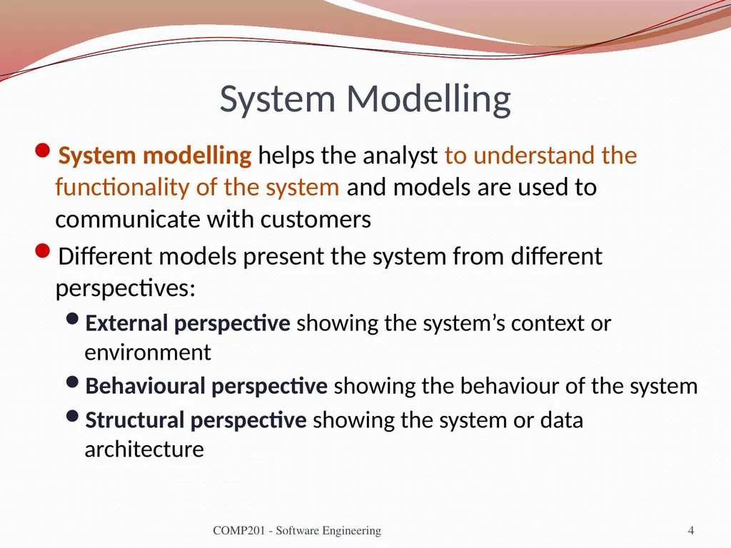
System Modelling System modelling helps the analyst to understand the functionality of the system and models are used to communicate with customers
Different models present the system from different perspectives:
External perspective showing the system’s context or environment
Behavioural perspective showing the behaviour of the system
Structural perspective showing the system or data architecture 4 COMP201 - Software Engineering<br>
Different models present the system from different perspectives:
External perspective showing the system’s context or environment
Behavioural perspective showing the behaviour of the system
Structural perspective showing the system or data architecture 4 COMP201 - Software Engineering<br>
05
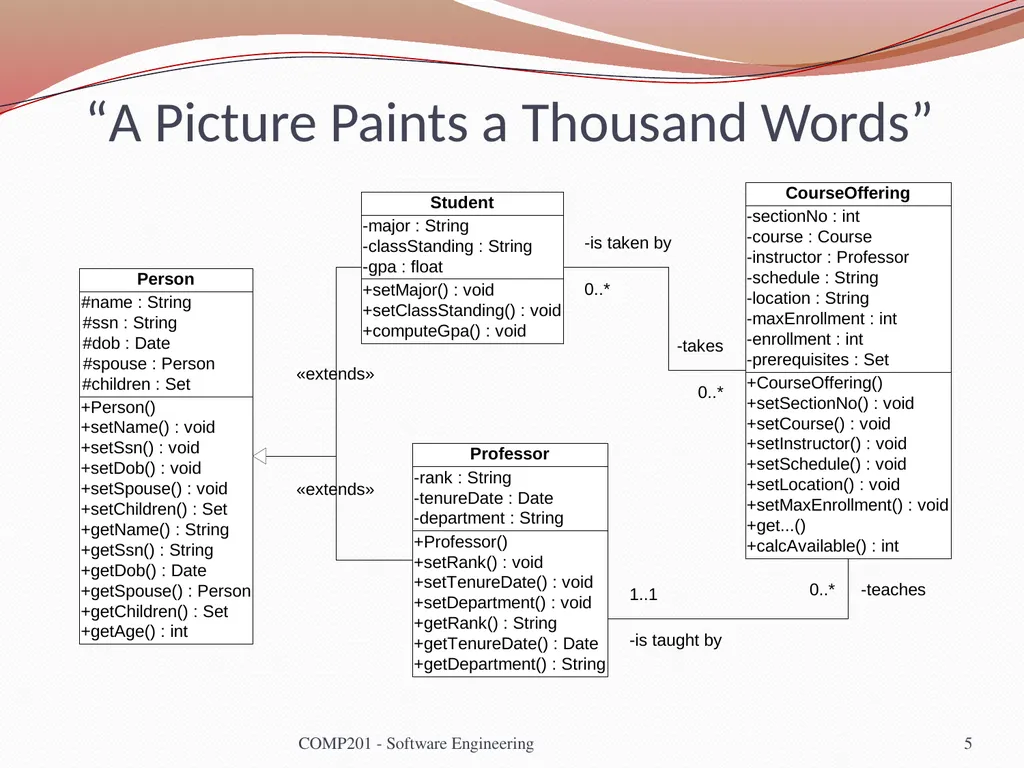
5 “A Picture Paints a Thousand Words” COMP201 - Software Engineering<br>
06
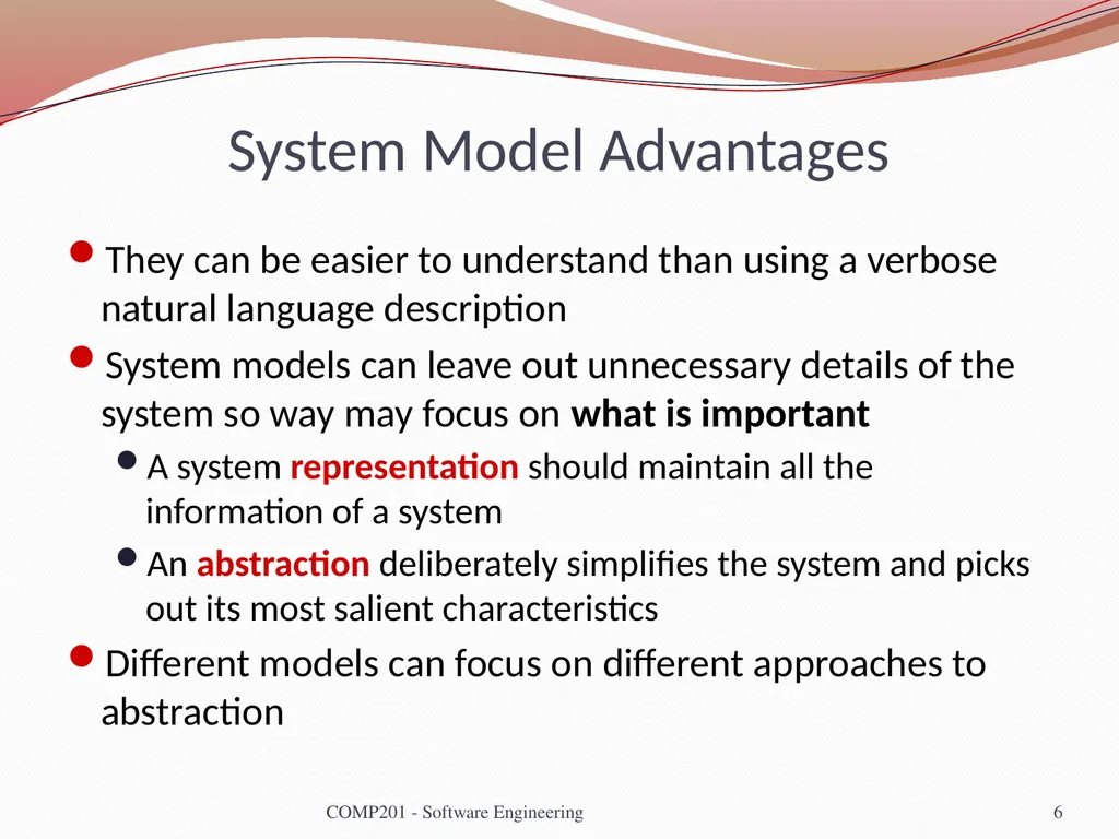
System Model Advantages They can be easier to understand than using a verbose natural language description
System models can leave out unnecessary details of the system so way may focus on what is important
A system representation should maintain all the information of a system
An abstraction deliberately simplifies the system and picks out its most salient characteristics
Different models can focus on different approaches to abstraction COMP201 - Software Engineering 6<br>
System models can leave out unnecessary details of the system so way may focus on what is important
A system representation should maintain all the information of a system
An abstraction deliberately simplifies the system and picks out its most salient characteristics
Different models can focus on different approaches to abstraction COMP201 - Software Engineering 6<br>
07
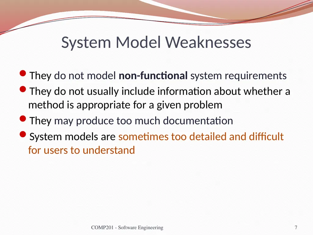
System Model Weaknesses They do not model non-functional system requirements
They do not usually include information about whether a method is appropriate for a given problem
They may produce too much documentation
System models are sometimes too detailed and difficult for users to understand 7 COMP201 - Software Engineering<br>
They do not usually include information about whether a method is appropriate for a given problem
They may produce too much documentation
System models are sometimes too detailed and difficult for users to understand 7 COMP201 - Software Engineering<br>
08
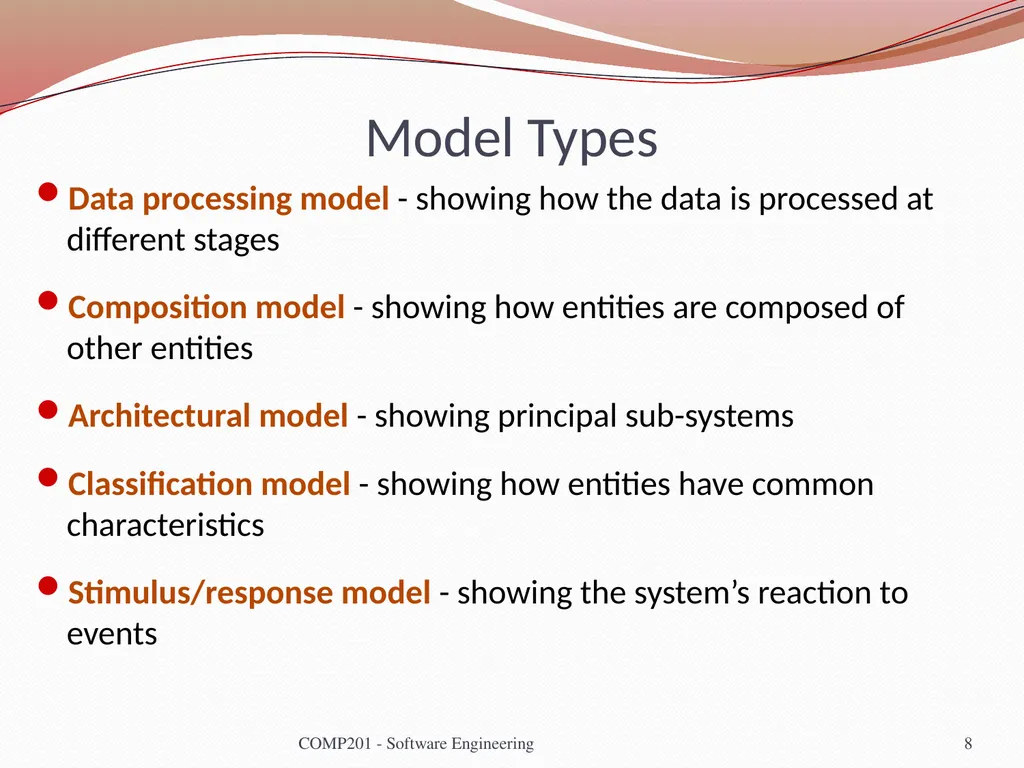
Model Types Data processing model - showing how the data is processed at different stages
Composition model - showing how entities are composed of other entities
Architectural model - showing principal sub-systems
Classification model - showing how entities have common characteristics
Stimulus/response model - showing the system’s reaction to events 8 COMP201 - Software Engineering<br>
Composition model - showing how entities are composed of other entities
Architectural model - showing principal sub-systems
Classification model - showing how entities have common characteristics
Stimulus/response model - showing the system’s reaction to events 8 COMP201 - Software Engineering<br>
09
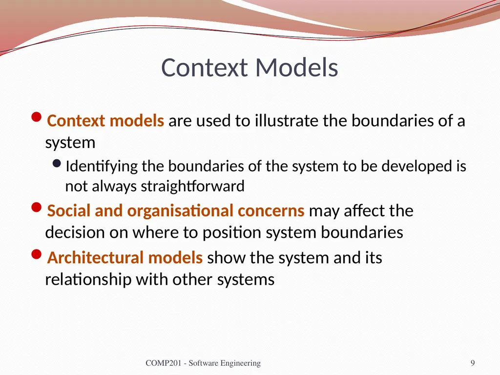
Context Models Context models are used to illustrate the boundaries of a system
Identifying the boundaries of the system to be developed is not always straightforward
Social and organisational concerns may affect the decision on where to position system boundaries
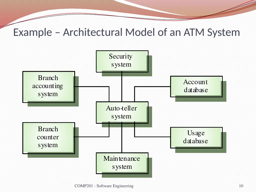
Architectural models show the system and its relationship with other systems 9 COMP201 - Software Engineering<br>
Identifying the boundaries of the system to be developed is not always straightforward
Social and organisational concerns may affect the decision on where to position system boundaries
Architectural models show the system and its relationship with other systems 9 COMP201 - Software Engineering<br>
10
Example – Architectural Model of an ATM System 10 COMP201 - Software Engineering<br>
11
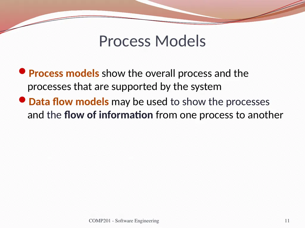
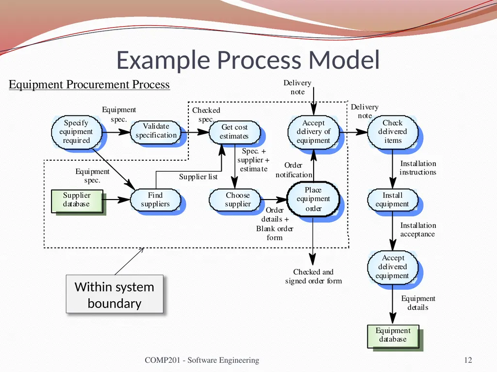
Process Models Process models show the overall process and the processes that are supported by the system
Data flow models may be used to show the processes and the flow of information from one process to another 11 COMP201 - Software Engineering<br>
Data flow models may be used to show the processes and the flow of information from one process to another 11 COMP201 - Software Engineering<br>
12
Example Process Model 12 COMP201 - Software Engineering Within system boundary Equipment Procurement Process<br>
13
Behavioural Models Behavioural models are used to describe the overall behaviour of a system
Two types of behavioural model
Data processing models that show how data is processed as it moves through the system
State machine models that show the systems response to events
Both of these models are required for a description of the system’s behaviour 13 COMP201 - Software Engineering<br>
Two types of behavioural model
Data processing models that show how data is processed as it moves through the system
State machine models that show the systems response to events
Both of these models are required for a description of the system’s behaviour 13 COMP201 - Software Engineering<br>
14
Data-Processing Models Data flow diagrams are used to model the system’s data processing
These show the processing steps as data flows through a system
IMPORTANT part of many analysis methods
Simple and intuitive notation
Show end-to-end processing of data 14 COMP201 - Software Engineering<br>
These show the processing steps as data flows through a system
IMPORTANT part of many analysis methods
Simple and intuitive notation
Show end-to-end processing of data 14 COMP201 - Software Engineering<br>
15
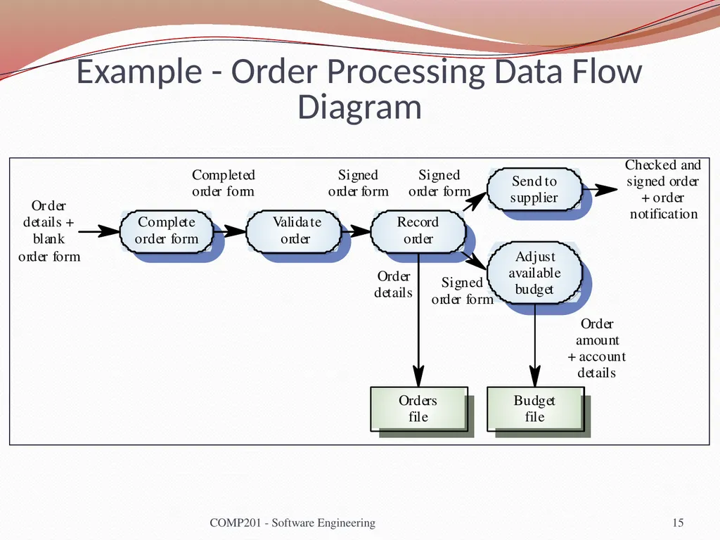
Example - Order Processing Data Flow Diagram 15 COMP201 - Software Engineering<br>
16
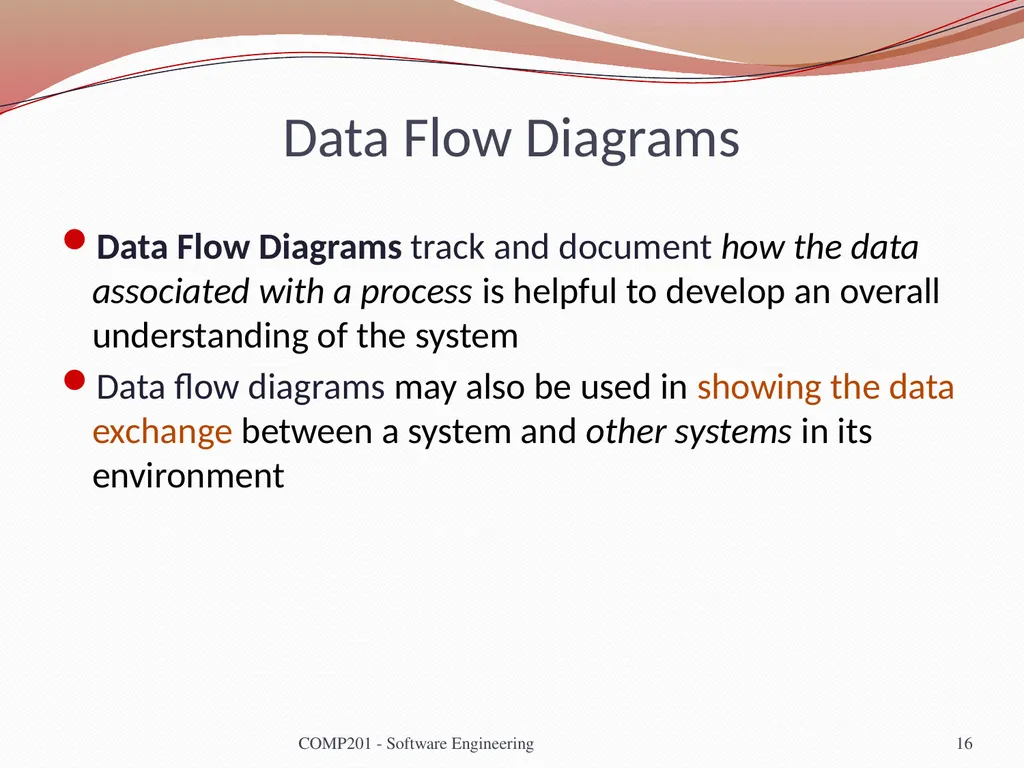
Data Flow Diagrams Data Flow Diagrams track and document how the data associated with a process is helpful to develop an overall understanding of the system
Data flow diagrams may also be used in showing the data exchange between a system and other systems in its environment 16 COMP201 - Software Engineering<br>
Data flow diagrams may also be used in showing the data exchange between a system and other systems in its environment 16 COMP201 - Software Engineering<br>
17
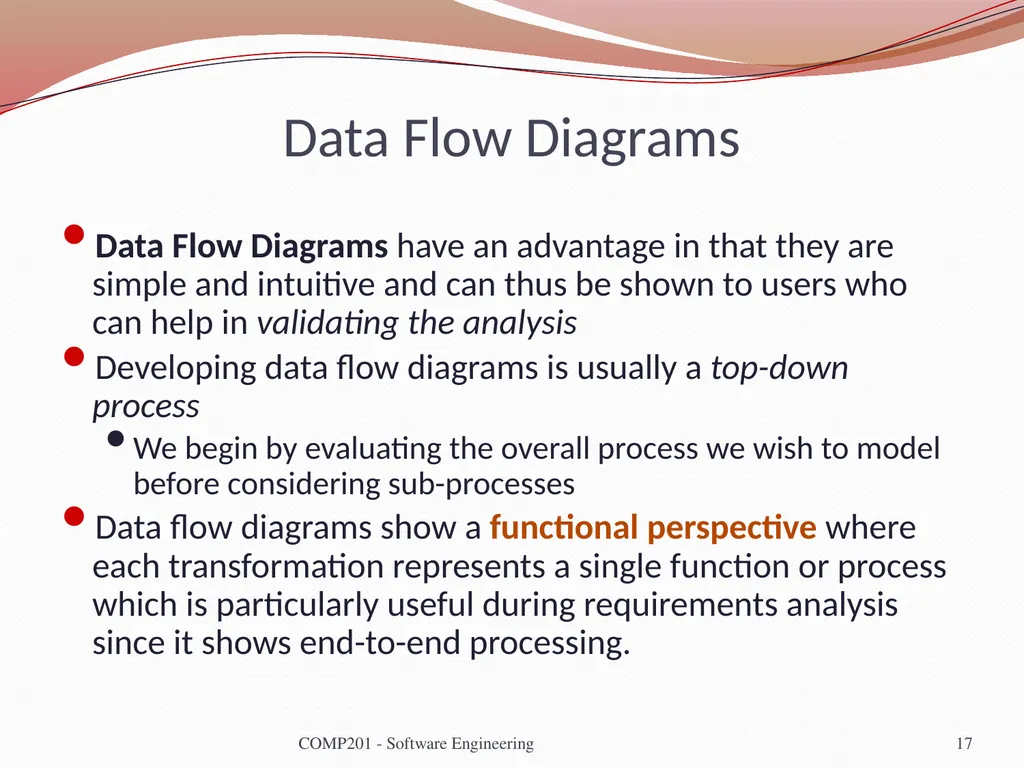
Data Flow Diagrams Data Flow Diagrams have an advantage in that they are simple and intuitive and can thus be shown to users who can help in validating the analysis
Developing data flow diagrams is usually a top-down process
We begin by evaluating the overall process we wish to model before considering sub-processes
Data flow diagrams show a functional perspective where each transformation represents a single function or process which is particularly useful during requirements analysis since it shows end-to-end processing. 17 COMP201 - Software Engineering<br>
Developing data flow diagrams is usually a top-down process
We begin by evaluating the overall process we wish to model before considering sub-processes
Data flow diagrams show a functional perspective where each transformation represents a single function or process which is particularly useful during requirements analysis since it shows end-to-end processing. 17 COMP201 - Software Engineering<br>
18
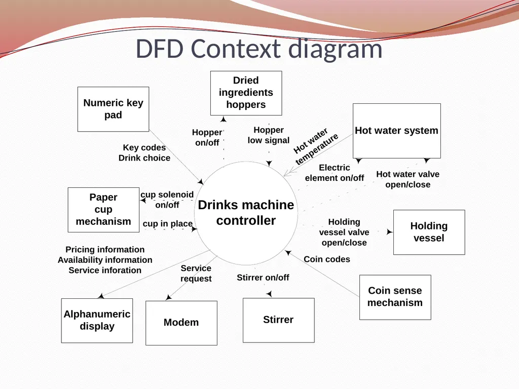
DFD Context diagram<br>
19
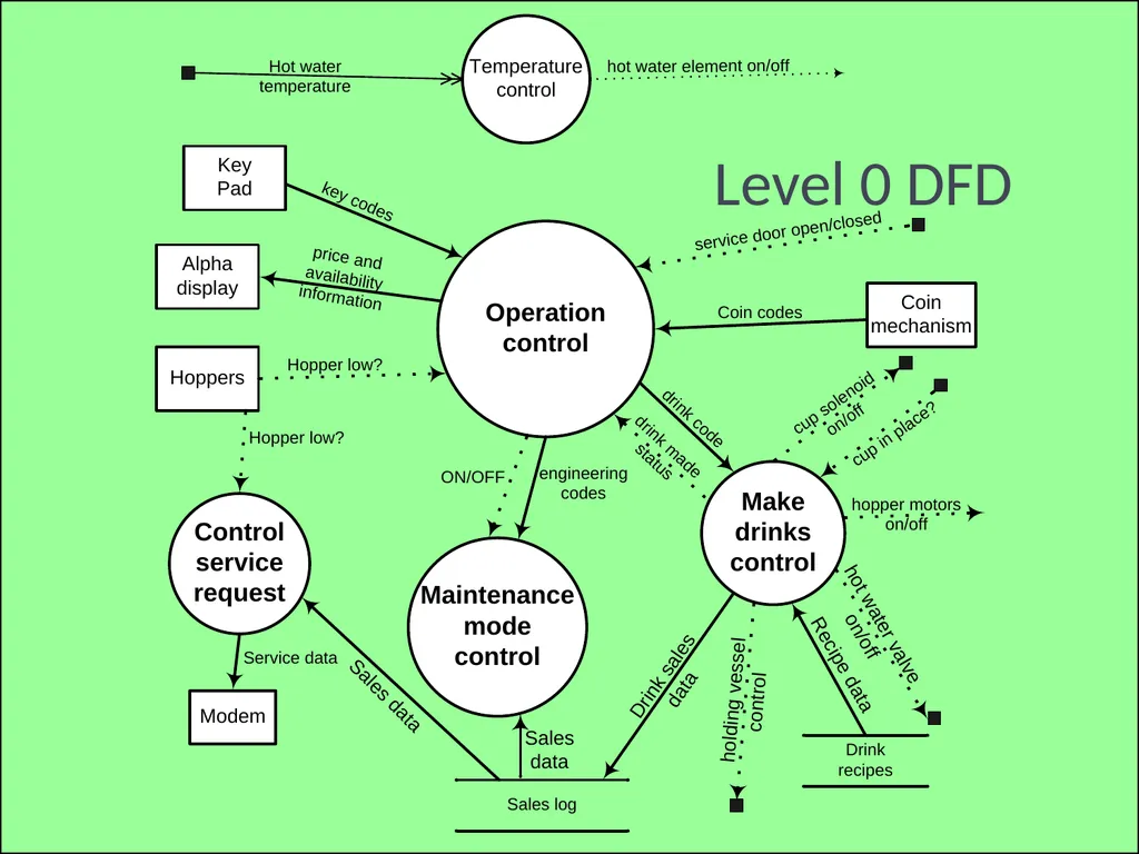
slide 19 3SFE519 S Coope 2004 Level 0 DFD<br>
20
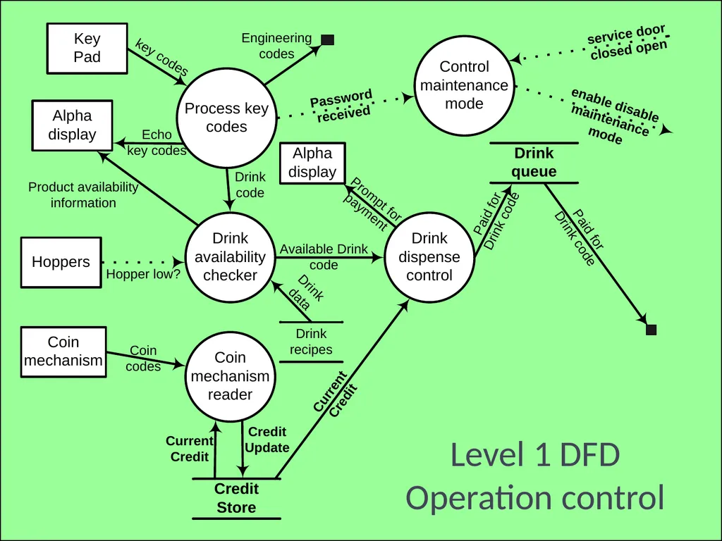
COMP201 - Software Engineering 20 slide 20 3SFE519 S Coope 2004 Level 1 DFD
Operation control<br>
21
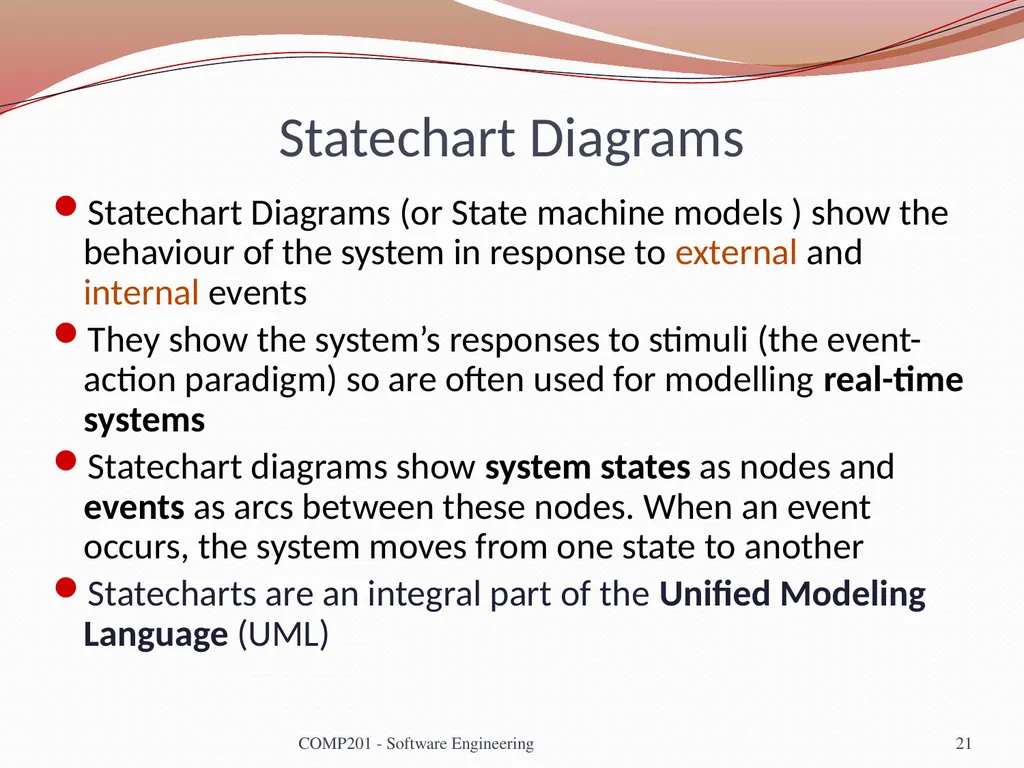
Statechart Diagrams Statechart Diagrams (or State machine models ) show the behaviour of the system in response to external and internal events
They show the system’s responses to stimuli (the event-action paradigm) so are often used for modelling real-time systems
Statechart diagrams show system states as nodes and events as arcs between these nodes. When an event occurs, the system moves from one state to another
Statecharts are an integral part of the Unified Modeling Language (UML) 21 COMP201 - Software Engineering<br>
They show the system’s responses to stimuli (the event-action paradigm) so are often used for modelling real-time systems
Statechart diagrams show system states as nodes and events as arcs between these nodes. When an event occurs, the system moves from one state to another
Statecharts are an integral part of the Unified Modeling Language (UML) 21 COMP201 - Software Engineering<br>
22
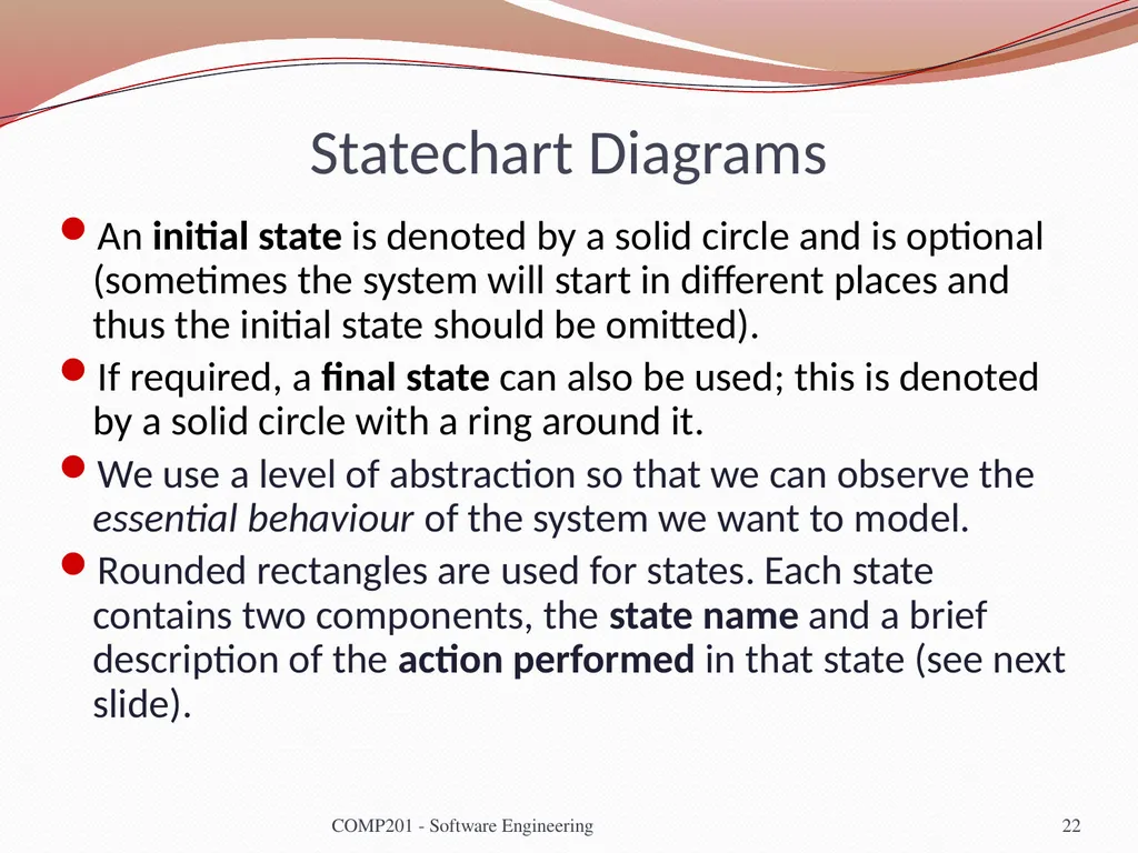
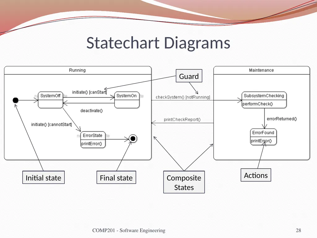
Statechart Diagrams An initial state is denoted by a solid circle and is optional (sometimes the system will start in different places and thus the initial state should be omitted).
If required, a final state can also be used; this is denoted by a solid circle with a ring around it.
We use a level of abstraction so that we can observe the essential behaviour of the system we want to model.
Rounded rectangles are used for states. Each state contains two components, the state name and a brief description of the action performed in that state (see next slide). 22 COMP201 - Software Engineering<br>
If required, a final state can also be used; this is denoted by a solid circle with a ring around it.
We use a level of abstraction so that we can observe the essential behaviour of the system we want to model.
Rounded rectangles are used for states. Each state contains two components, the state name and a brief description of the action performed in that state (see next slide). 22 COMP201 - Software Engineering<br>
23
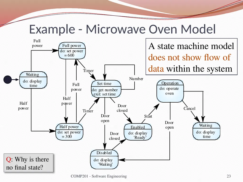
Example - Microwave Oven Model A state machine model does not show flow of data within the system 23 COMP201 - Software Engineering Q: Why is there no final state?<br>
24
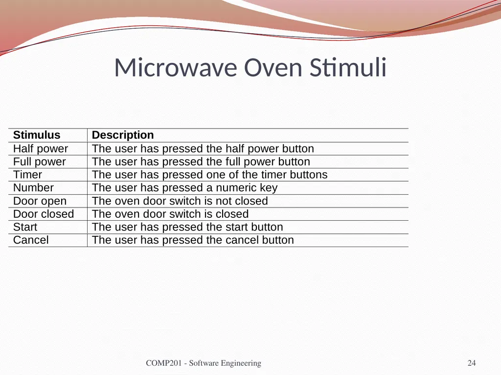
Microwave Oven Stimuli 24 COMP201 - Software Engineering<br>
25
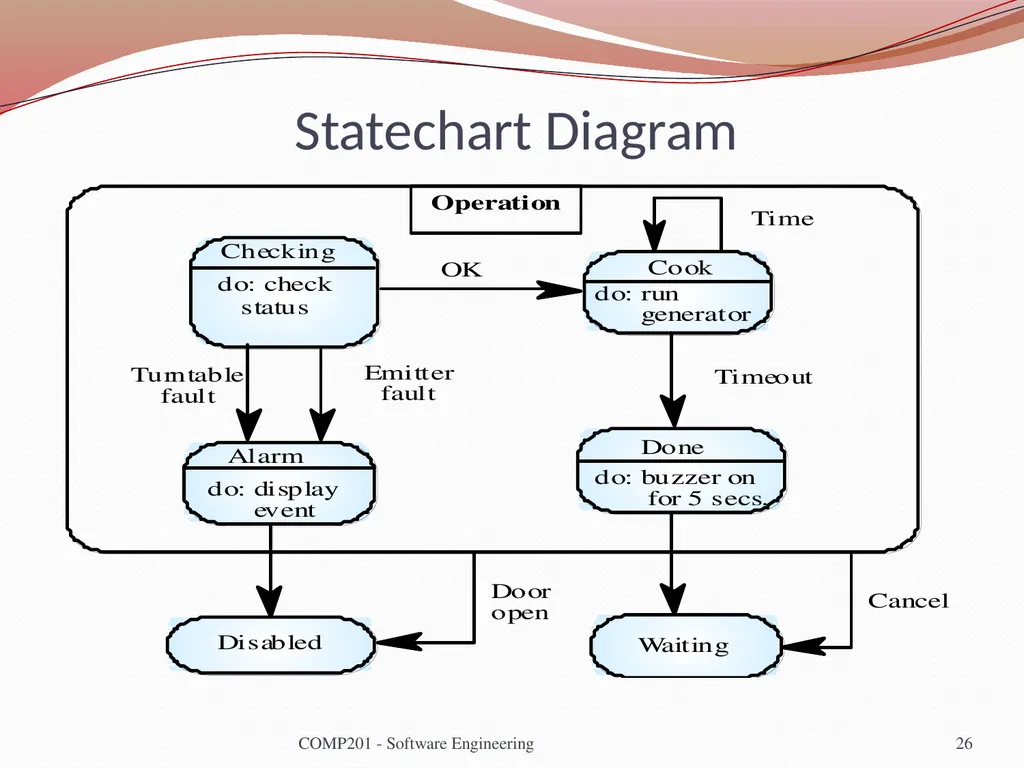
Statecharts Statecharts also allow the decomposition of a model into sub-models (see figure on next slide).
A brief description of the actions is included following the ‘do’ in each state (the word “do” is optional).
Can be complemented by tables describing the states and the stimuli. 25 COMP201 - Software Engineering<br>
A brief description of the actions is included following the ‘do’ in each state (the word “do” is optional).
Can be complemented by tables describing the states and the stimuli. 25 COMP201 - Software Engineering<br>
26
Statechart Diagram 26 COMP201 - Software Engineering<br>
27
Statechart Diagrams The label on an arc can denote the method called to move from one state to the next (the event).
A guard is used to ensure that the system only moves from one state to the other if the expression is satisfied.
A state can contain a subdiagram within it (also called a composite state). This is useful for example when we wish to model a subsystem or substates.
On the next slide, we can see all these elements of a UML statechart diagram 27 COMP201 - Software Engineering<br>
A guard is used to ensure that the system only moves from one state to the other if the expression is satisfied.
A state can contain a subdiagram within it (also called a composite state). This is useful for example when we wish to model a subsystem or substates.
On the next slide, we can see all these elements of a UML statechart diagram 27 COMP201 - Software Engineering<br>
28
Statechart Diagrams 28 COMP201 - Software Engineering Initial state Final state Composite
States Guard Actions<br>
States Guard Actions<br>
29
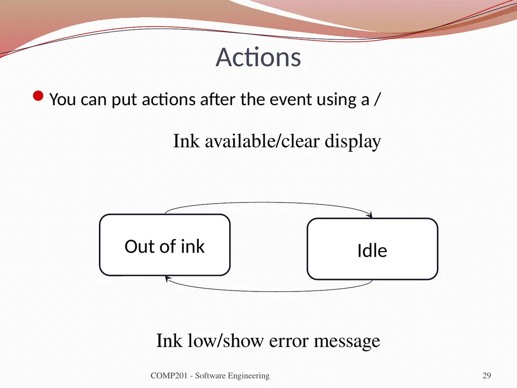
Actions You can put actions after the event using a / COMP201 - Software Engineering 29 Out of ink Idle Ink available/clear display Ink low/show error message<br>
30
More hints on state charts Often have an Idle state where the process is not active
All states need some exit (no deadlock, even in error conditions)
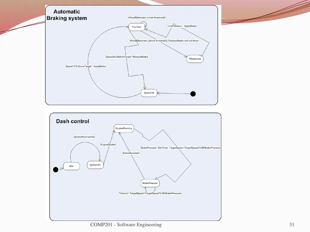
Use multiple state charts to keep the design simple
Do NOT need to have a state chart as sub state of other state chart
System can be described by multiple state machines running concurrently COMP201 - Software Engineering 30<br>
All states need some exit (no deadlock, even in error conditions)
Use multiple state charts to keep the design simple
Do NOT need to have a state chart as sub state of other state chart
System can be described by multiple state machines running concurrently COMP201 - Software Engineering 30<br>
31
COMP201 - Software Engineering 31<br>
32
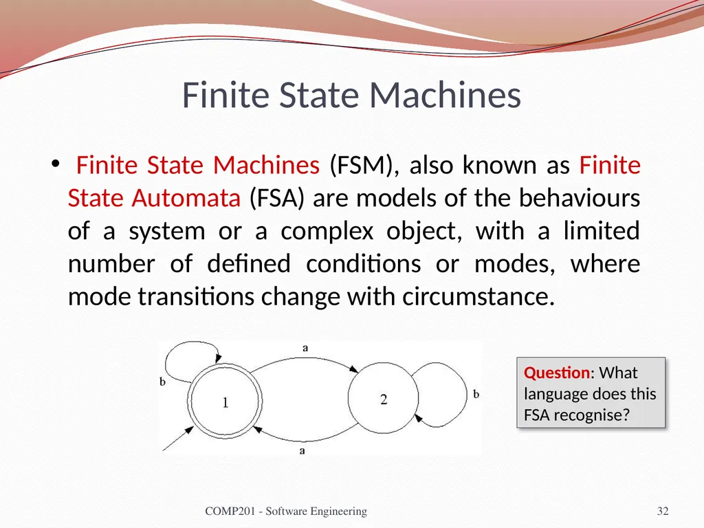
Finite State Machines Finite State Machines (FSM), also known as Finite State Automata (FSA) are models of the behaviours of a system or a complex object, with a limited number of defined conditions or modes, where mode transitions change with circumstance. 32 COMP201 - Software Engineering Question: What language does this FSA recognise?<br>
33
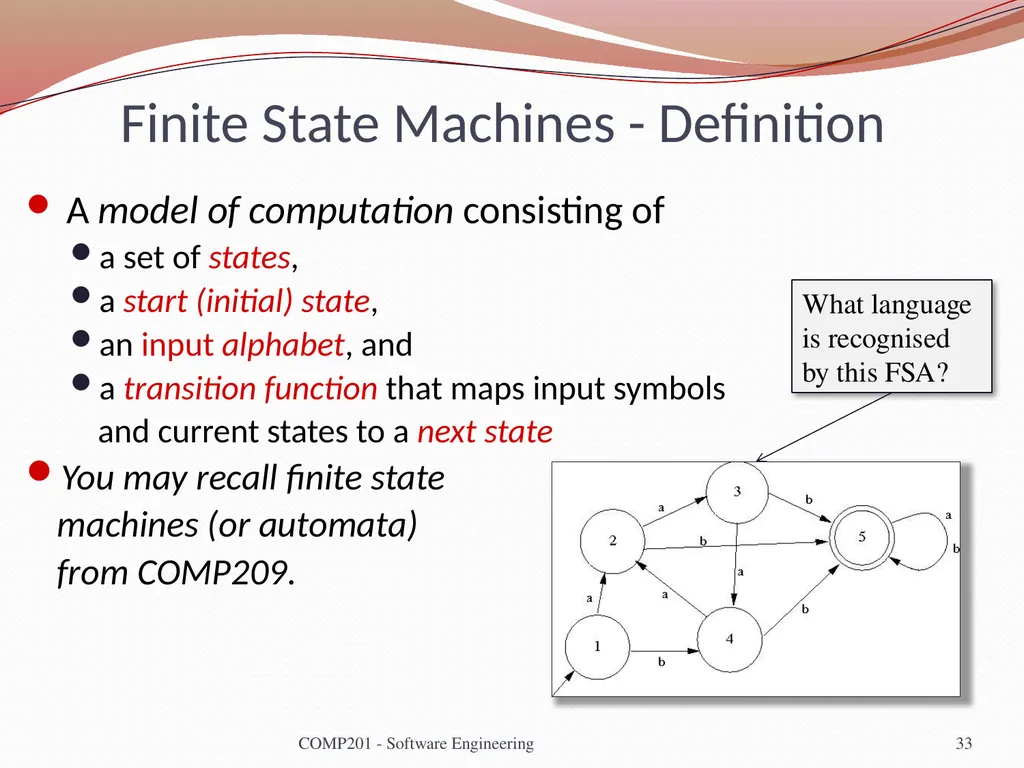
Finite State Machines - Definition A model of computation consisting of
a set of states,
a start (initial) state,
an input alphabet, and
a transition function that maps input symbols
and current states to a next state
You may recall finite state
machines (or automata)
from COMP209. 33 COMP201 - Software Engineering What language is recognised by this FSA?<br>
a set of states,
a start (initial) state,
an input alphabet, and
a transition function that maps input symbols
and current states to a next state
You may recall finite state
machines (or automata)
from COMP209. 33 COMP201 - Software Engineering What language is recognised by this FSA?<br>
34
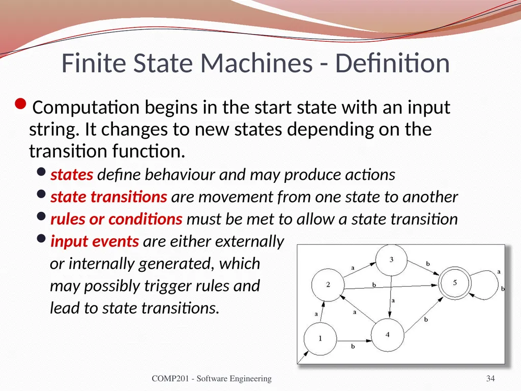
Finite State Machines - Definition Computation begins in the start state with an input string. It changes to new states depending on the transition function.
states define behaviour and may produce actions
state transitions are movement from one state to another
rules or conditions must be met to allow a state transition
input events are either externally
or internally generated, which
may possibly trigger rules and
lead to state transitions. 34 COMP201 - Software Engineering<br>
states define behaviour and may produce actions
state transitions are movement from one state to another
rules or conditions must be met to allow a state transition
input events are either externally
or internally generated, which
may possibly trigger rules and
lead to state transitions. 34 COMP201 - Software Engineering<br>
35
Lecture Key Points A model is an abstract system view. Complementary types of model provide different system information.
Context models show the position of a system in its environment with other systems and processes.
Data flow models may be used to model the data processing in a system.
State machine models model the system’s behaviour in response to internal or external events<br>
Context models show the position of a system in its environment with other systems and processes.
Data flow models may be used to model the data processing in a system.
State machine models model the system’s behaviour in response to internal or external events<br>