
Supplemental Restraint Systems CHAPTER 6 Knowledge



Description: Supplemental Restraint Systems CHAPTER 6 Knowledge Objectives (1 of 2) Define the following terms and explain their role in vehicle rescue incidents: Accelerometer Air bag control unit (ACU) Deployment zone Distancing Electronic control
Related Topics
Download Presentation
"Supplemental Restraint Systems CHAPTER 6 Knowledge" is the property of its rightful owner. Permission is granted to download and print the materials on this website for personal, non-commercial use only, and to display it on your personal computer provided you do not modify the materials and that you retain all copyright notices contained in the materials. By downloading content from our website, you accept the terms of this agreement.
Presentation Transcript
slide1. Supplemental Restraint Systems CHAPTER 6<br>
slide2. Knowledge Objectives (1 of 2) Define the following terms and explain their role in vehicle rescue incidents:
Accelerometer
Air bag control unit (ACU)
Deployment zone
Distancing
Electronic control unit (ECU)
Initiator
Identify the differences between active and passive vehicle restraint systems.<br>
slide3. Knowledge Objectives (2 of 2) List the steps in the air bag deployment process.
Identify the basic components of an air bag system.
List the types and locations of air bags present in passenger vehicles.
Explain the importance of expose and cut.
Describe seat belt pretensioning systems and explain their activation.
Explain safety precautions to protect rescuers in extrication from vehicles with air bag systems.<br>
slide4. Introduction In 1967, the NHTSA issued Federal Motor Vehicle Safety Standards (FMVSSs).
To protect the public from risks of injury or death resulting from poor design, construction, or performance of a motor vehicle
FMVSS 209, Seat Belt Assemblies
FMVSS 208, Occupant Crash Protection
FMVSS 214, Side Impact Protection
FMVSS 226, Ejection Mitigation<br>
slide5. Air Bags (1 of 7) Fatalities from motor vehicle accidents increased dramatically in the 1970s because occupants did not wear seat belts while driving.
Automobile industry introduced an air cushion restraint system to counter this trend.
At the time, it was considered to be a replacement to the seat belt.
More accident fatalities occurred.
As time went by, the air cushion restraint system faded away, and seat belt education and enforcement started to increase.<br>
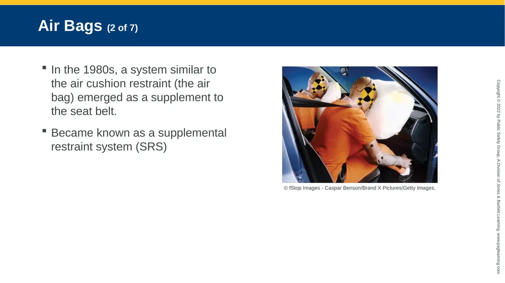
slide6. Air Bags (2 of 7) In the 1980s, a system similar to the air cushion restraint (the air bag) emerged as a supplement to the seat belt.
Became known as a supplemental restraint system (SRS) © fStop Images - Caspar Benson/Brand X Pictures/Getty Images.<br>
slide7. Air Bags (3 of 7) Manual seat belts are active restraint devices.
Air bags are passive restraint devices.
In 1984, FMVSS 208 was amended to mandate that motor vehicles must be equipped with a passive restraint system.
Included air bags and automatic seat belts
Most vehicles offered only a single-stage air bag system.<br>
slide8. Air Bags (4 of 7) First-generation air bags would fire at a preset discharge rate and pressure fitted only for average-sized males.
Children, women, or smaller-statured individuals were not factored in.
Out-of-position occupants or unbelted occupants would be subject to a crushing force.
Caused FMVSS 208 to be amended to accommodate different-sized individuals
Mandated that air bags be depowered and a deactivation switch be added to passenger-side air bags (second-generation air bags)<br>
slide9. Air Bags (5 of 7) Smart air bag systems automatically adjust the pressure in the air bag by using inflators.
Deployment force is based on
Crash severity
Occupant’s weight
Proximity to the air bag
Seat belt usage
Seat position<br>
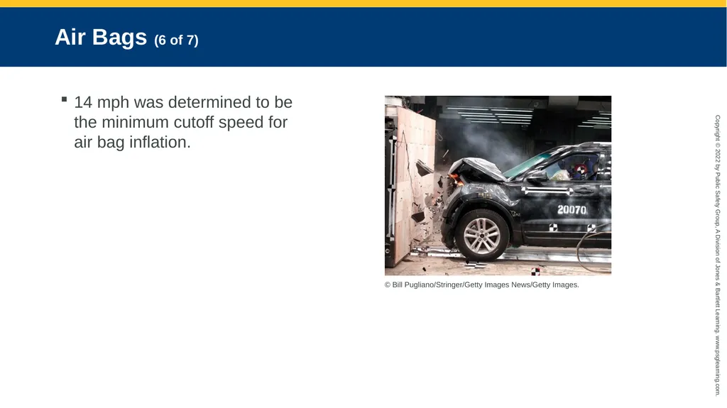
slide10. Air Bags (6 of 7) 14 mph was determined to be the minimum cutoff speed for air bag inflation. © Bill Pugliano/Stringer/Getty Images News/Getty Images.<br>
slide11. Air Bags (7 of 7) Features to protect occupants from air bag injuries:
Dual-stage or multistage inflation process
Suppression system shuts down air bag if occupant classification system detects a child.<br>
slide12. Air Bag Deployment Process (1 of 2) Crash itself
Crash sensor (accelerometer) detecting deceleration
Air bag deploying and inflating
Occupant moving forward and striking the bag as deflation occurs<br>
slide13. Air Bag Deployment Process (2 of 2) Certain factors can change some of these crash sequence dynamics:
Seat belt system
Size and seated distance of the occupant
Severity of the crash
The entire crash process takes approximately 100 to 125 milliseconds.
The gas inside the air bag must be precisely set with the correct volume to prevent the occupant from striking the steering wheel or dash.<br>
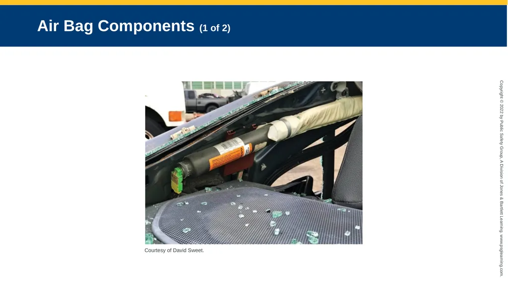
slide14. Air Bag Components (1 of 2) Courtesy of David Sweet.<br>
slide15. Air Bag Components (2 of 2) Consists of strong, durable nylon or blended material
Coated with a powdered substance, normally consisting of talcum, chalk, or cornstarch
Comes equipped with several tethers designed to manage the speed of deployment
Air bag cover is a plastic material designed to tear apart and separate when the air bag inflates.
Size of the bag will vary.
Driver and front passenger air bags are mandatory in all vehicles.<br>
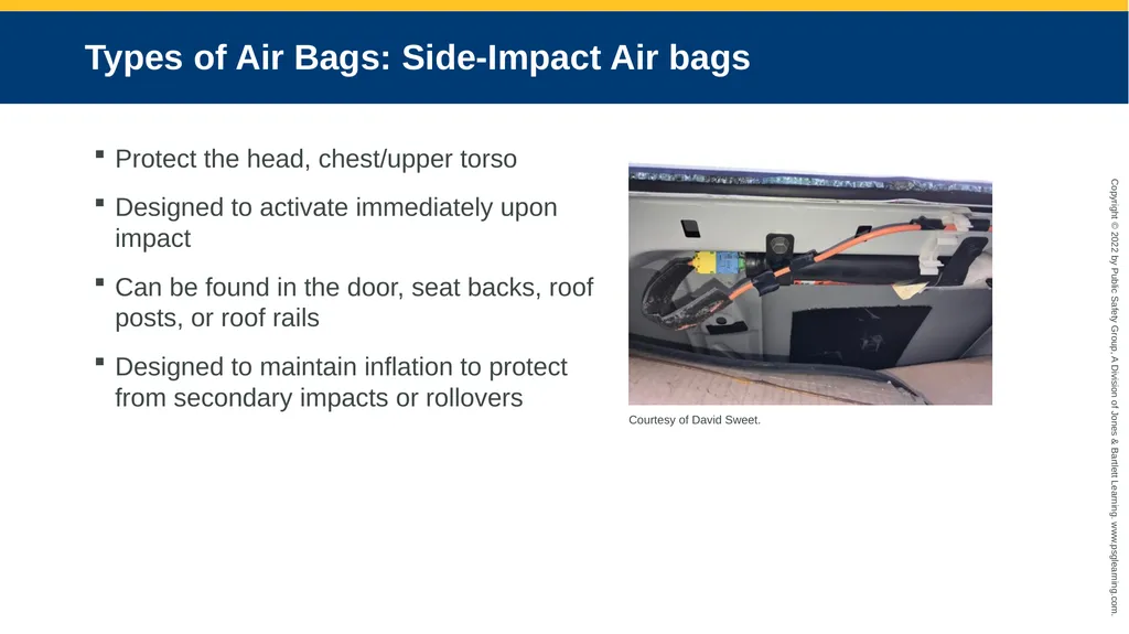
slide16. Types of Air Bags: Side-Impact Air bags Protect the head, chest/upper torso
Designed to activate immediately upon impact
Can be found in the door, seat backs, roof posts, or roof rails
Designed to maintain inflation to protect from secondary impacts or rollovers Courtesy of David Sweet.<br>
slide17. Types of Air Bags: Center Air Bag Designed to protect from secondary impacts
Also protects from side impacts that occur on the opposite side of the vehicle
Deploys in an upward and forward position between the front and rear seats<br>
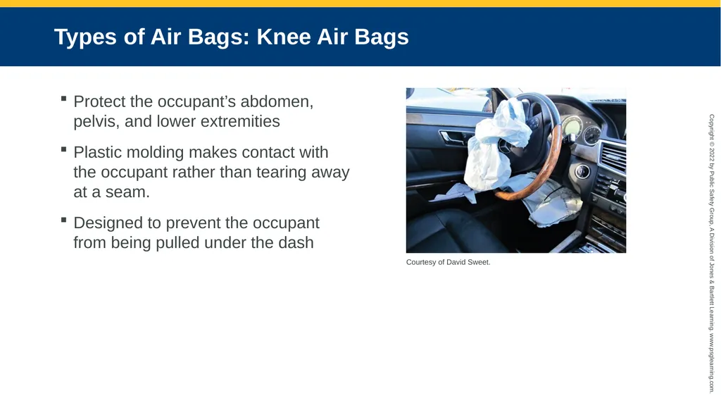
slide18. Types of Air Bags: Knee Air Bags Protect the occupant’s abdomen, pelvis, and lower extremities
Plastic molding makes contact with the occupant rather than tearing away at a seam.
Designed to prevent the occupant from being pulled under the dash Courtesy of David Sweet.<br>
slide19. Types of Air Bags: Other (1 of 2) Seat belt air bags
Protect torso and pelvic area
Work in conjunction with the seat belt pretensioning system to reduce the “clothesline effect”
Seat cushion air bag
Positioned just under the front section of seat
Raises the hip and knee area of the occupant, in turn reducing the forward movement of the chest and abdomen<br>
slide20. Types of Air Bags: Other (2 of 2) Rear seat deployment air bag systems
Deployed from the center roof area, seat belt, door, or roof post
Outside pedestrian protection system
May be an air bag positioned in the front bumper/hood area
No standardized locations for air bags or inflation cylinders<br>
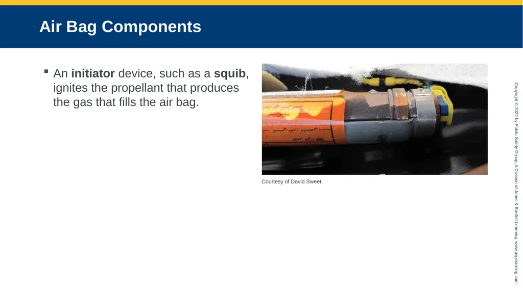
slide21. Air Bag Components An initiator device, such as a squib, ignites the propellant that produces the gas that fills the air bag. Courtesy of David Sweet.<br>
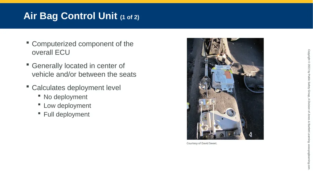
slide22. Air Bag Control Unit (1 of 2) Computerized component of the overall ECU
Generally located in center of vehicle and/or between the seats
Calculates deployment level
No deployment
Low deployment
Full deployment Courtesy of David Sweet.<br>
slide23. Air Bag Control Unit (2 of 2) Designed to eliminate unnecessary deployments
Works in conjunction with other sensors
ECU contains an energy capacitor that acts as a back-up system in any power disruption (30 s to 30 min).
Can also simultaneously activate a seat belt pretension system for added protection
Some ECUs record and store information from accidents that have occurred.<br>
slide24. Inflator/Propellant Fills up air bag instantaneously
Critical consideration of the technical rescuer; generally positioned in the cut zone areas
Always inspect before you dissect.<br>
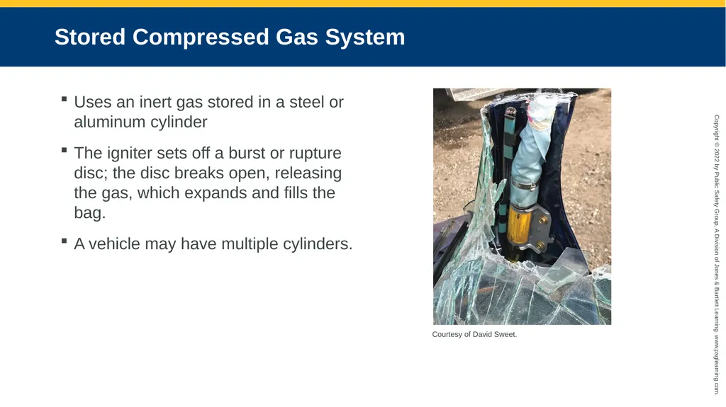
slide25. Stored Compressed Gas System Uses an inert gas stored in a steel or aluminum cylinder
The igniter sets off a burst or rupture disc; the disc breaks open, releasing the gas, which expands and fills the bag.
A vehicle may have multiple cylinders. Courtesy of David Sweet.<br>
slide26. Multistage Inflators Cylinders that can comprise two separate chambers of compressed gas
One with a large amount of product
Another with a small amount of product
Can fire independently or together
If the ECU determines that a full deployment is needed, both chambers will fire simultaneously.<br>
slide27. Gas Generation System (1 of 2) Uses a chemical reaction that rapidly produces the gas (commonly nitrogen) that fills the bag.
Sodium azide is most common (very volatile).
Common driver-side air bag housing units contain approximately 2 ounces of sodium azide.
Used in pellet form for easier product containment
Passenger-side air bag housing unit can contain approximately 7 ounces of sodium azide.
Must fill the passenger-side area<br>
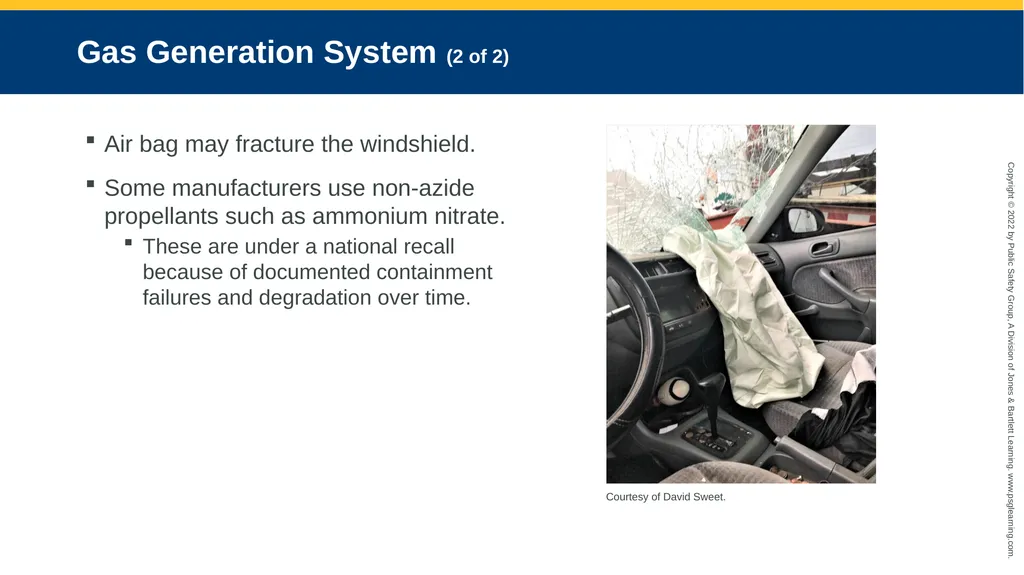
slide28. Gas Generation System (2 of 2) Air bag may fracture the windshield.
Some manufacturers use non-azide propellants such as ammonium nitrate.
These are under a national recall because of documented containment failures and degradation over time. Courtesy of David Sweet.<br>
slide29. Hybrid Type Inflator Consists of both a gas-generation pyrotechnic propellant and a compressed gas
Two chambers; first chamber uses gas-producing propellant, second uses compressed gas
Common to side-impact air bags
Designed to react and deploy at a much faster rate (10–15 ms) because of the proximity of the occupant to the impact<br>
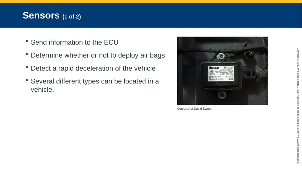
slide30. Sensors (1 of 2) Send information to the ECU
Determine whether or not to deploy air bags
Detect a rapid deceleration of the vehicle
Several different types can be located in a vehicle. Courtesy of David Sweet.<br>
slide31. Sensors (2 of 2) Occupant classification system
Seat position sensor (proximity of the occupant to the air bag)
Seat belt sensor (engagement of seat belt)
Occupant weight sensor (determines whether the occupant has met a preset weight)
Will also measure rescuer’s weight<br>
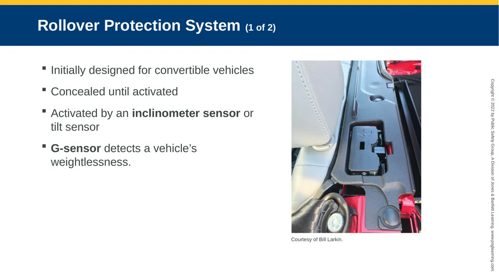
slide32. Rollover Protection System (1 of 2) Initially designed for convertible vehicles
Concealed until activated
Activated by an inclinometer sensor or tilt sensor
G-sensor detects a vehicle’s weightlessness. Courtesy of Bill Larkin.<br>
slide33. Rollover Protection System (2 of 2) To activate, sensors must detect a significant vehicle tilt with lateral acceleration.
Exercise caution when operating around a vehicle containing an undeployed roll bar.
Avoid placing any parts of the body over an undeployed roll bar.
Technical rescuer must follow the same safety guidelines and electrical disconnection procedures that are established for vehicle air bag systems.<br>
slide34. Seat Belt Systems Active restraint systems designed to maintain the position of the occupant when a force from a sudden acceleration or deceleration is applied
By design, the seat belt webbing material stretches and absorbs the force of the occupant’s body weight controlling against the potential interior impact.
Have a tensile strength of over 6000 lb
Can be anchored in two-, three-, or four-point systems<br>
slide35. Seat Belt Types (1 of 2) Retractable
Has the webbing wound up in a gear housing under a tensioned spring mechanism
Automatically takes up slack when the belt is released
Has a locking mechanism web clamp that prevents any further release of the webbing.
Nonretractable
Remains static, with slack being taken up manually<br>
slide36. Seat Belt Types (2 of 2) Load-limiting device
Reduces the force applied by the seat belt when it locks in place after sudden force
Can be incorporated into the webbing material or into a torsion bar attached to the retractor gear
A fold is stitched into the belt that is set to tear when a present amount of force is applied, preventing the belt from locking up
Gradually releases the tension that can cause injury<br>
slide37. Seat Belt Pretensioning System (1 of 3) Can be activated in conjunction with air bags or act independently
Can be set up to operate at the belt buckle attachment or at the anchor attachment
The belt buckle will operate by pulling down and/or back on the buckle itself by means of a cable attachment or piston rod.
Commonly activated by a small pyrotechnic charge or firing mechanism, which draws back on the cable or piston attachment<br>
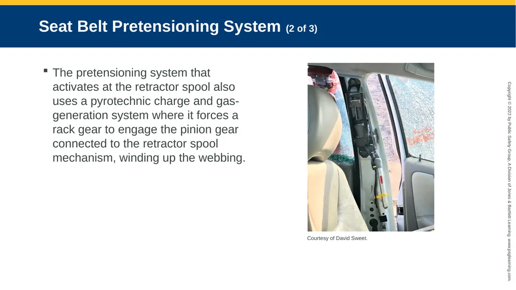
slide38. Seat Belt Pretensioning System (2 of 3) The pretensioning system that activates at the retractor spool also uses a pyrotechnic charge and gas-generation system where it forces a rack gear to engage the pinion gear connected to the retractor spool mechanism, winding up the webbing. Courtesy of David Sweet.<br>
slide39. Seat Belt Pretensioning System (3 of 3) Mechanical pretensioning systems use a torsion spring that is pretensioned and operates by means of a pendulum.
When the pendulum is offset by a crash, the spring is released and draws back on the retractor that rapidly spools the webbing.
Other types of pretensioning systems use a series of steel balls in a chamber tube that are forced through a cog wheel–type mechanism that engages the retractor that spools the webbing and locks the retractor once the slack is removed from the belt.<br>
slide40. Dissection Seat belt assemblies can be housed in any post or column, under the seats, or in the center console.
If cutting through a post, the molding must be removed to reveal the pretensioning system in order to cut around the device.
Do not rip or tear the vehicle apart; comprehend the action taken.
One must dissect the vehicle section by section.
This step-by-step technical process requires continuous training.<br>
slide41. Emergency Procedures Never assume the air bag is dead.
Energy capacitor can store power for 30 minutes.
Air bag inflators are “live” until deployed.
Attempting to disable the inflator can cause the air bag to deploy.
Licensed technicians must install, repair, or remove air bags.<br>
slide42. Disconnecting Power Several things can be done to ensure that power is disconnected.
Remember there is a backup energy system with storage capacitors.
Remember it may be difficult to adjust seats if electrical beneficial systems are installed in the vehicle.<br>
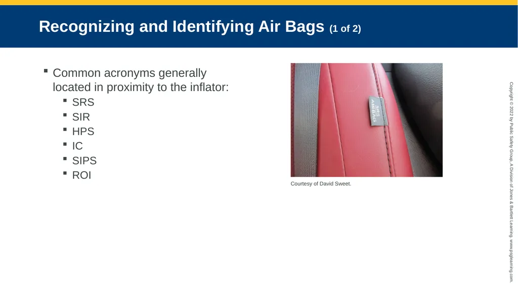
slide43. Recognizing and Identifying Air Bags (1 of 2) Common acronyms generally located in proximity to the inflator:
SRS
SIR
HPS
IC
SIPS
ROI Courtesy of David Sweet.<br>
slide44. Recognizing and Identifying Air Bags (2 of 2) Acronyms/letters may be embossed, raised, or sewn into the material.
Starting in 1998, all vehicles must contain a driver- and passenger-side air bag.
All other air bags will have to be located by the rescuer.
One of the assignments for the rescuer positioned in the vehicle is to scan the entire interior for air bag locations.<br>
slide45. Distancing Once an air bag location has been identified, the next precaution is to maintain proper distance from the deployment zone.
Proper distancing:
10 inches (25 cm) for driver side
20–25 inches (51–64 cm) for passenger side
5–15 inches (13–38 cm) for side-impact bags
Only recommendations; each manufacturer differs<br>
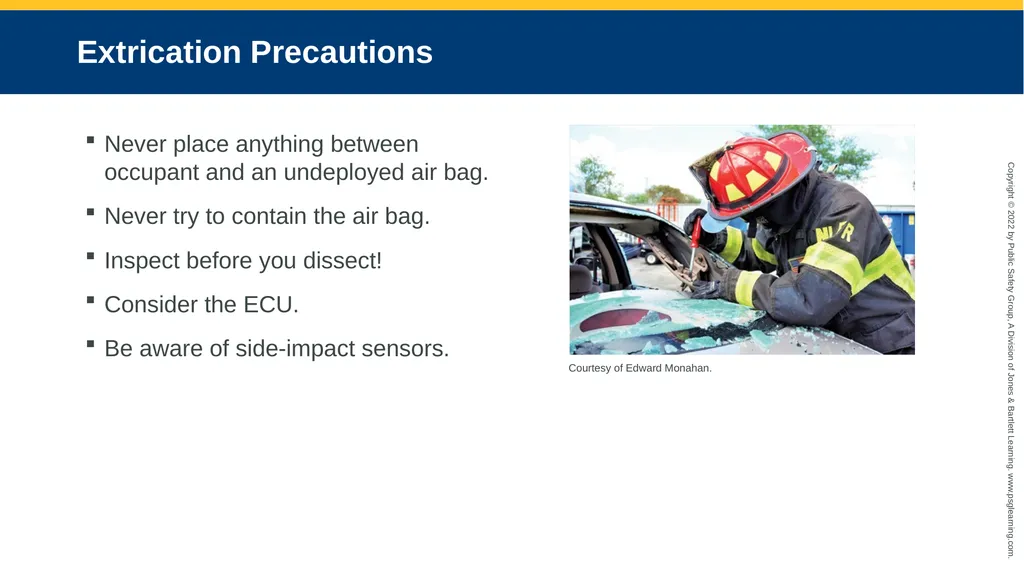
slide46. Extrication Precautions Never place anything between occupant and an undeployed air bag.
Never try to contain the air bag.
Inspect before you dissect!
Consider the ECU.
Be aware of side-impact sensors. Courtesy of Edward Monahan.<br>
slide47. Summary (1 of 3) In 1967, the NHTSA issued a federal mandate titled FMVSS 209, Seat Belt Assemblies. This was the first of many subsequent regulations that outlined minimum safety requirements for motor vehicles mandating compliance from vehicle manufacturers.
In the 1980s, the air bag became known as an SRS by working in conjunction with the seat belt.
A four-stage process occurs when an air bag deploys in a crash sequence: the crash itself, the crash sensor detecting deceleration, the air bag deploying and inflating, and the occupant moving forward and striking the bag as deflation occurs.
Several components make up an air bag, including the air bag, initiator, ECU, propellant, inflator, and sensors.<br>
slide48. Summary (2 of 3) ROPS were initially designed for convertible vehicles to protect occupants in vehicle rollover incidents. Roll bars are concealed until activated by sensors.
Seat belts, also known as safety belts, are active restraint systems designed to maintain the position of the occupant when a force from a sudden acceleration or deceleration is applied.
Seat belts can be retractable or nonretractable. The retractable type has the webbing wound up in a gear housing under a tensioned spring mechanism that automatically takes up slack when the belt is released. The nonretractable type remains static, with slack being taken up manually.<br>
slide49. Summary (3 of 3) Pretensioning systems are designed to retract automatically through a mechanical or electrical/pyrotechnical mechanism. They can be activated in conjunction with the vehicle air bags from the ECU or act independently.
Never assume that an air bag is dead just because the power has been disconnected; a vehicle air bag system comes equipped with an energy capacitor, which can store power for up to 30 minutes in some models.
Eliminating potential hazards of SRS systems may include disconnecting power, recognizing and identifying air bags, distancing, and taking additional extrication precautions.<br>
slide2. Knowledge Objectives (1 of 2) Define the following terms and explain their role in vehicle rescue incidents:
Accelerometer
Air bag control unit (ACU)
Deployment zone
Distancing
Electronic control unit (ECU)
Initiator
Identify the differences between active and passive vehicle restraint systems.<br>
slide3. Knowledge Objectives (2 of 2) List the steps in the air bag deployment process.
Identify the basic components of an air bag system.
List the types and locations of air bags present in passenger vehicles.
Explain the importance of expose and cut.
Describe seat belt pretensioning systems and explain their activation.
Explain safety precautions to protect rescuers in extrication from vehicles with air bag systems.<br>
slide4. Introduction In 1967, the NHTSA issued Federal Motor Vehicle Safety Standards (FMVSSs).
To protect the public from risks of injury or death resulting from poor design, construction, or performance of a motor vehicle
FMVSS 209, Seat Belt Assemblies
FMVSS 208, Occupant Crash Protection
FMVSS 214, Side Impact Protection
FMVSS 226, Ejection Mitigation<br>
slide5. Air Bags (1 of 7) Fatalities from motor vehicle accidents increased dramatically in the 1970s because occupants did not wear seat belts while driving.
Automobile industry introduced an air cushion restraint system to counter this trend.
At the time, it was considered to be a replacement to the seat belt.
More accident fatalities occurred.
As time went by, the air cushion restraint system faded away, and seat belt education and enforcement started to increase.<br>
slide6. Air Bags (2 of 7) In the 1980s, a system similar to the air cushion restraint (the air bag) emerged as a supplement to the seat belt.
Became known as a supplemental restraint system (SRS) © fStop Images - Caspar Benson/Brand X Pictures/Getty Images.<br>
slide7. Air Bags (3 of 7) Manual seat belts are active restraint devices.
Air bags are passive restraint devices.
In 1984, FMVSS 208 was amended to mandate that motor vehicles must be equipped with a passive restraint system.
Included air bags and automatic seat belts
Most vehicles offered only a single-stage air bag system.<br>
slide8. Air Bags (4 of 7) First-generation air bags would fire at a preset discharge rate and pressure fitted only for average-sized males.
Children, women, or smaller-statured individuals were not factored in.
Out-of-position occupants or unbelted occupants would be subject to a crushing force.
Caused FMVSS 208 to be amended to accommodate different-sized individuals
Mandated that air bags be depowered and a deactivation switch be added to passenger-side air bags (second-generation air bags)<br>
slide9. Air Bags (5 of 7) Smart air bag systems automatically adjust the pressure in the air bag by using inflators.
Deployment force is based on
Crash severity
Occupant’s weight
Proximity to the air bag
Seat belt usage
Seat position<br>
slide10. Air Bags (6 of 7) 14 mph was determined to be the minimum cutoff speed for air bag inflation. © Bill Pugliano/Stringer/Getty Images News/Getty Images.<br>
slide11. Air Bags (7 of 7) Features to protect occupants from air bag injuries:
Dual-stage or multistage inflation process
Suppression system shuts down air bag if occupant classification system detects a child.<br>
slide12. Air Bag Deployment Process (1 of 2) Crash itself
Crash sensor (accelerometer) detecting deceleration
Air bag deploying and inflating
Occupant moving forward and striking the bag as deflation occurs<br>
slide13. Air Bag Deployment Process (2 of 2) Certain factors can change some of these crash sequence dynamics:
Seat belt system
Size and seated distance of the occupant
Severity of the crash
The entire crash process takes approximately 100 to 125 milliseconds.
The gas inside the air bag must be precisely set with the correct volume to prevent the occupant from striking the steering wheel or dash.<br>
slide14. Air Bag Components (1 of 2) Courtesy of David Sweet.<br>
slide15. Air Bag Components (2 of 2) Consists of strong, durable nylon or blended material
Coated with a powdered substance, normally consisting of talcum, chalk, or cornstarch
Comes equipped with several tethers designed to manage the speed of deployment
Air bag cover is a plastic material designed to tear apart and separate when the air bag inflates.
Size of the bag will vary.
Driver and front passenger air bags are mandatory in all vehicles.<br>
slide16. Types of Air Bags: Side-Impact Air bags Protect the head, chest/upper torso
Designed to activate immediately upon impact
Can be found in the door, seat backs, roof posts, or roof rails
Designed to maintain inflation to protect from secondary impacts or rollovers Courtesy of David Sweet.<br>
slide17. Types of Air Bags: Center Air Bag Designed to protect from secondary impacts
Also protects from side impacts that occur on the opposite side of the vehicle
Deploys in an upward and forward position between the front and rear seats<br>
slide18. Types of Air Bags: Knee Air Bags Protect the occupant’s abdomen, pelvis, and lower extremities
Plastic molding makes contact with the occupant rather than tearing away at a seam.
Designed to prevent the occupant from being pulled under the dash Courtesy of David Sweet.<br>
slide19. Types of Air Bags: Other (1 of 2) Seat belt air bags
Protect torso and pelvic area
Work in conjunction with the seat belt pretensioning system to reduce the “clothesline effect”
Seat cushion air bag
Positioned just under the front section of seat
Raises the hip and knee area of the occupant, in turn reducing the forward movement of the chest and abdomen<br>
slide20. Types of Air Bags: Other (2 of 2) Rear seat deployment air bag systems
Deployed from the center roof area, seat belt, door, or roof post
Outside pedestrian protection system
May be an air bag positioned in the front bumper/hood area
No standardized locations for air bags or inflation cylinders<br>
slide21. Air Bag Components An initiator device, such as a squib, ignites the propellant that produces the gas that fills the air bag. Courtesy of David Sweet.<br>
slide22. Air Bag Control Unit (1 of 2) Computerized component of the overall ECU
Generally located in center of vehicle and/or between the seats
Calculates deployment level
No deployment
Low deployment
Full deployment Courtesy of David Sweet.<br>
slide23. Air Bag Control Unit (2 of 2) Designed to eliminate unnecessary deployments
Works in conjunction with other sensors
ECU contains an energy capacitor that acts as a back-up system in any power disruption (30 s to 30 min).
Can also simultaneously activate a seat belt pretension system for added protection
Some ECUs record and store information from accidents that have occurred.<br>
slide24. Inflator/Propellant Fills up air bag instantaneously
Critical consideration of the technical rescuer; generally positioned in the cut zone areas
Always inspect before you dissect.<br>
slide25. Stored Compressed Gas System Uses an inert gas stored in a steel or aluminum cylinder
The igniter sets off a burst or rupture disc; the disc breaks open, releasing the gas, which expands and fills the bag.
A vehicle may have multiple cylinders. Courtesy of David Sweet.<br>
slide26. Multistage Inflators Cylinders that can comprise two separate chambers of compressed gas
One with a large amount of product
Another with a small amount of product
Can fire independently or together
If the ECU determines that a full deployment is needed, both chambers will fire simultaneously.<br>
slide27. Gas Generation System (1 of 2) Uses a chemical reaction that rapidly produces the gas (commonly nitrogen) that fills the bag.
Sodium azide is most common (very volatile).
Common driver-side air bag housing units contain approximately 2 ounces of sodium azide.
Used in pellet form for easier product containment
Passenger-side air bag housing unit can contain approximately 7 ounces of sodium azide.
Must fill the passenger-side area<br>
slide28. Gas Generation System (2 of 2) Air bag may fracture the windshield.
Some manufacturers use non-azide propellants such as ammonium nitrate.
These are under a national recall because of documented containment failures and degradation over time. Courtesy of David Sweet.<br>
slide29. Hybrid Type Inflator Consists of both a gas-generation pyrotechnic propellant and a compressed gas
Two chambers; first chamber uses gas-producing propellant, second uses compressed gas
Common to side-impact air bags
Designed to react and deploy at a much faster rate (10–15 ms) because of the proximity of the occupant to the impact<br>
slide30. Sensors (1 of 2) Send information to the ECU
Determine whether or not to deploy air bags
Detect a rapid deceleration of the vehicle
Several different types can be located in a vehicle. Courtesy of David Sweet.<br>
slide31. Sensors (2 of 2) Occupant classification system
Seat position sensor (proximity of the occupant to the air bag)
Seat belt sensor (engagement of seat belt)
Occupant weight sensor (determines whether the occupant has met a preset weight)
Will also measure rescuer’s weight<br>
slide32. Rollover Protection System (1 of 2) Initially designed for convertible vehicles
Concealed until activated
Activated by an inclinometer sensor or tilt sensor
G-sensor detects a vehicle’s weightlessness. Courtesy of Bill Larkin.<br>
slide33. Rollover Protection System (2 of 2) To activate, sensors must detect a significant vehicle tilt with lateral acceleration.
Exercise caution when operating around a vehicle containing an undeployed roll bar.
Avoid placing any parts of the body over an undeployed roll bar.
Technical rescuer must follow the same safety guidelines and electrical disconnection procedures that are established for vehicle air bag systems.<br>
slide34. Seat Belt Systems Active restraint systems designed to maintain the position of the occupant when a force from a sudden acceleration or deceleration is applied
By design, the seat belt webbing material stretches and absorbs the force of the occupant’s body weight controlling against the potential interior impact.
Have a tensile strength of over 6000 lb
Can be anchored in two-, three-, or four-point systems<br>
slide35. Seat Belt Types (1 of 2) Retractable
Has the webbing wound up in a gear housing under a tensioned spring mechanism
Automatically takes up slack when the belt is released
Has a locking mechanism web clamp that prevents any further release of the webbing.
Nonretractable
Remains static, with slack being taken up manually<br>
slide36. Seat Belt Types (2 of 2) Load-limiting device
Reduces the force applied by the seat belt when it locks in place after sudden force
Can be incorporated into the webbing material or into a torsion bar attached to the retractor gear
A fold is stitched into the belt that is set to tear when a present amount of force is applied, preventing the belt from locking up
Gradually releases the tension that can cause injury<br>
slide37. Seat Belt Pretensioning System (1 of 3) Can be activated in conjunction with air bags or act independently
Can be set up to operate at the belt buckle attachment or at the anchor attachment
The belt buckle will operate by pulling down and/or back on the buckle itself by means of a cable attachment or piston rod.
Commonly activated by a small pyrotechnic charge or firing mechanism, which draws back on the cable or piston attachment<br>
slide38. Seat Belt Pretensioning System (2 of 3) The pretensioning system that activates at the retractor spool also uses a pyrotechnic charge and gas-generation system where it forces a rack gear to engage the pinion gear connected to the retractor spool mechanism, winding up the webbing. Courtesy of David Sweet.<br>
slide39. Seat Belt Pretensioning System (3 of 3) Mechanical pretensioning systems use a torsion spring that is pretensioned and operates by means of a pendulum.
When the pendulum is offset by a crash, the spring is released and draws back on the retractor that rapidly spools the webbing.
Other types of pretensioning systems use a series of steel balls in a chamber tube that are forced through a cog wheel–type mechanism that engages the retractor that spools the webbing and locks the retractor once the slack is removed from the belt.<br>
slide40. Dissection Seat belt assemblies can be housed in any post or column, under the seats, or in the center console.
If cutting through a post, the molding must be removed to reveal the pretensioning system in order to cut around the device.
Do not rip or tear the vehicle apart; comprehend the action taken.
One must dissect the vehicle section by section.
This step-by-step technical process requires continuous training.<br>
slide41. Emergency Procedures Never assume the air bag is dead.
Energy capacitor can store power for 30 minutes.
Air bag inflators are “live” until deployed.
Attempting to disable the inflator can cause the air bag to deploy.
Licensed technicians must install, repair, or remove air bags.<br>
slide42. Disconnecting Power Several things can be done to ensure that power is disconnected.
Remember there is a backup energy system with storage capacitors.
Remember it may be difficult to adjust seats if electrical beneficial systems are installed in the vehicle.<br>
slide43. Recognizing and Identifying Air Bags (1 of 2) Common acronyms generally located in proximity to the inflator:
SRS
SIR
HPS
IC
SIPS
ROI Courtesy of David Sweet.<br>
slide44. Recognizing and Identifying Air Bags (2 of 2) Acronyms/letters may be embossed, raised, or sewn into the material.
Starting in 1998, all vehicles must contain a driver- and passenger-side air bag.
All other air bags will have to be located by the rescuer.
One of the assignments for the rescuer positioned in the vehicle is to scan the entire interior for air bag locations.<br>
slide45. Distancing Once an air bag location has been identified, the next precaution is to maintain proper distance from the deployment zone.
Proper distancing:
10 inches (25 cm) for driver side
20–25 inches (51–64 cm) for passenger side
5–15 inches (13–38 cm) for side-impact bags
Only recommendations; each manufacturer differs<br>
slide46. Extrication Precautions Never place anything between occupant and an undeployed air bag.
Never try to contain the air bag.
Inspect before you dissect!
Consider the ECU.
Be aware of side-impact sensors. Courtesy of Edward Monahan.<br>
slide47. Summary (1 of 3) In 1967, the NHTSA issued a federal mandate titled FMVSS 209, Seat Belt Assemblies. This was the first of many subsequent regulations that outlined minimum safety requirements for motor vehicles mandating compliance from vehicle manufacturers.
In the 1980s, the air bag became known as an SRS by working in conjunction with the seat belt.
A four-stage process occurs when an air bag deploys in a crash sequence: the crash itself, the crash sensor detecting deceleration, the air bag deploying and inflating, and the occupant moving forward and striking the bag as deflation occurs.
Several components make up an air bag, including the air bag, initiator, ECU, propellant, inflator, and sensors.<br>
slide48. Summary (2 of 3) ROPS were initially designed for convertible vehicles to protect occupants in vehicle rollover incidents. Roll bars are concealed until activated by sensors.
Seat belts, also known as safety belts, are active restraint systems designed to maintain the position of the occupant when a force from a sudden acceleration or deceleration is applied.
Seat belts can be retractable or nonretractable. The retractable type has the webbing wound up in a gear housing under a tensioned spring mechanism that automatically takes up slack when the belt is released. The nonretractable type remains static, with slack being taken up manually.<br>
slide49. Summary (3 of 3) Pretensioning systems are designed to retract automatically through a mechanical or electrical/pyrotechnical mechanism. They can be activated in conjunction with the vehicle air bags from the ECU or act independently.
Never assume that an air bag is dead just because the power has been disconnected; a vehicle air bag system comes equipped with an energy capacitor, which can store power for up to 30 minutes in some models.
Eliminating potential hazards of SRS systems may include disconnecting power, recognizing and identifying air bags, distancing, and taking additional extrication precautions.<br>