
UNIT-IV UNIT - IV: NEED FOR DISTRIBUTED GENERATION
AS
Published · 59 slides · 0 views
1 / 1




Description
UNIT-IV UNIT - IV: NEED FOR DISTRIBUTED GENERATION Renewable sources in distributed generation Current scenario in distributed generation Planning of DGs Siting and sizing of DGs Optimal placement of DG sources in distribution
Related Topics
Share
Embed code
Download this presentation From Below
"UNIT-IV UNIT - IV: NEED FOR DISTRIBUTED GENERATION" is the property of its rightful owner. Permission is granted to download and print the materials on this website for personal, non-commercial use only, and to display it on your personal computer provided you do not modify the materials and that you retain all copyright notices contained in the materials. By downloading content from our website, you accept the terms of this agreement.
Presentation Transcript
01
UNIT-IV<br>
02
UNIT - IV: NEED FOR DISTRIBUTED GENERATION
Renewable sources in distributed generation – Current scenario in distributed generation – Planning of DGs – Siting and sizing of DGs – Optimal placement of DG sources in distribution systems.<br>
Renewable sources in distributed generation – Current scenario in distributed generation – Planning of DGs – Siting and sizing of DGs – Optimal placement of DG sources in distribution systems.<br>
03
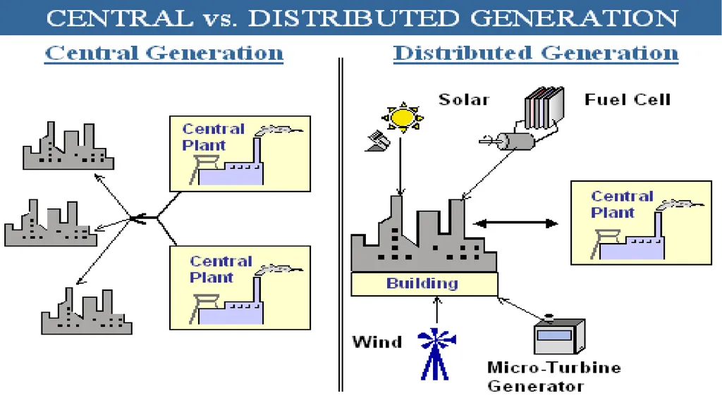
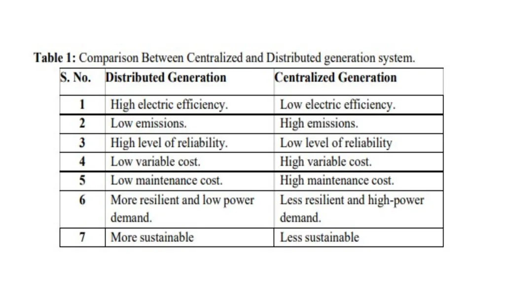
Distributed generation is an emerging concept in the electricity sector which represents good alternatives for electricity supply instead of traditional centralized power generation concept. DG can be defined as the generation units that are connected at distribution network level and close to end users.
DG is not necessarily green power generation. Renewable DG technologies are more preferred options due to their environmental benefits.<br>
DG is not necessarily green power generation. Renewable DG technologies are more preferred options due to their environmental benefits.<br>
04
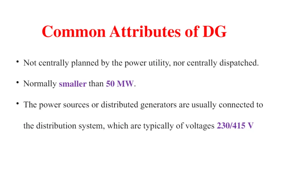
Distributed generation is defined as small scale generation located at or near the load centers.
Distributed generation is often used as back up power to enhance reliability, avoiding network charges, reducing line losses, providing environmental benefits, providing alternative sources of supply in markets
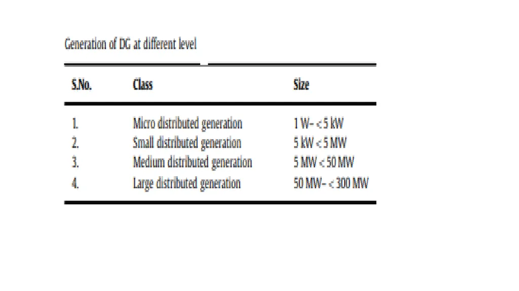
DG range from 1kw PV installation, 1MW engine generators to 1000 MW offshore wind forms or more.
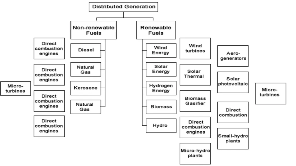
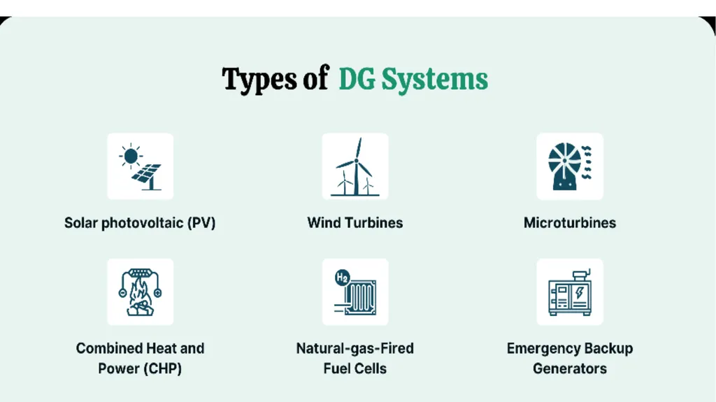
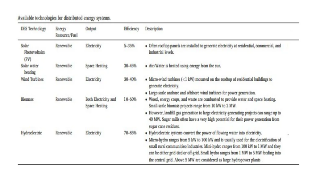
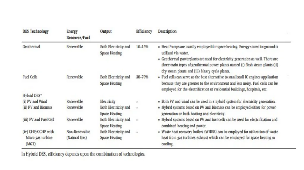
The present available DG technologies are Reciprocating engines, Gas turbines, Micro turbines, Fuel cells, Photovoltaic systems, Wind energy, Biomass etc.<br>
Distributed generation is often used as back up power to enhance reliability, avoiding network charges, reducing line losses, providing environmental benefits, providing alternative sources of supply in markets
DG range from 1kw PV installation, 1MW engine generators to 1000 MW offshore wind forms or more.
The present available DG technologies are Reciprocating engines, Gas turbines, Micro turbines, Fuel cells, Photovoltaic systems, Wind energy, Biomass etc.<br>
05
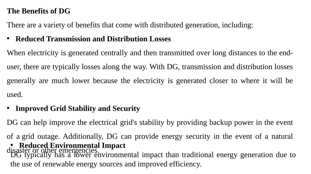
The Benefits of DG
There are a variety of benefits that come with distributed generation, including:
Reduced Transmission and Distribution Losses
When electricity is generated centrally and then transmitted over long distances to the end-user, there are typically losses along the way. With DG, transmission and distribution losses generally are much lower because the electricity is generated closer to where it will be used.
Improved Grid Stability and Security
DG can help improve the electrical grid's stability by providing backup power in the event of a grid outage. Additionally, DG can provide energy security in the event of a natural disaster or other emergencies. Reduced Environmental Impact
DG typically has a lower environmental impact than traditional energy generation due to the use of renewable energy sources and improved efficiency.<br>
There are a variety of benefits that come with distributed generation, including:
Reduced Transmission and Distribution Losses
When electricity is generated centrally and then transmitted over long distances to the end-user, there are typically losses along the way. With DG, transmission and distribution losses generally are much lower because the electricity is generated closer to where it will be used.
Improved Grid Stability and Security
DG can help improve the electrical grid's stability by providing backup power in the event of a grid outage. Additionally, DG can provide energy security in the event of a natural disaster or other emergencies. Reduced Environmental Impact
DG typically has a lower environmental impact than traditional energy generation due to the use of renewable energy sources and improved efficiency.<br>
06
Uses of Distributed Generation The following are some examples of how distributed generations are used:
For supporting minor loads, distributed generation may be more cost-effective than even short-line additions.
It may be more cost-effective than laying a power cable in a remote area.
Provide the main energy, with a reserve and supplementary power provided by the grid.
Facilities can be designed to sell more electricity than the facility requires. For reserve energy throughout power system downtime, for buildings that require continuous operation — such as hospitals, military bases, and prisons — and for companies that have significant expenses for enforced blackouts, such as data centers, banks, and the telecom and industrial sectors. Provide better power quality for sensitive electrical as well as other devices.
Using a renewable energy source or a cleaner power ability to minimize air pollutants at a location.
To postpone or stop investing in transmission and distribution systems.
To give the utility with power or capability.<br>
For supporting minor loads, distributed generation may be more cost-effective than even short-line additions.
It may be more cost-effective than laying a power cable in a remote area.
Provide the main energy, with a reserve and supplementary power provided by the grid.
Facilities can be designed to sell more electricity than the facility requires. For reserve energy throughout power system downtime, for buildings that require continuous operation — such as hospitals, military bases, and prisons — and for companies that have significant expenses for enforced blackouts, such as data centers, banks, and the telecom and industrial sectors. Provide better power quality for sensitive electrical as well as other devices.
Using a renewable energy source or a cleaner power ability to minimize air pollutants at a location.
To postpone or stop investing in transmission and distribution systems.
To give the utility with power or capability.<br>
07
Solar PV
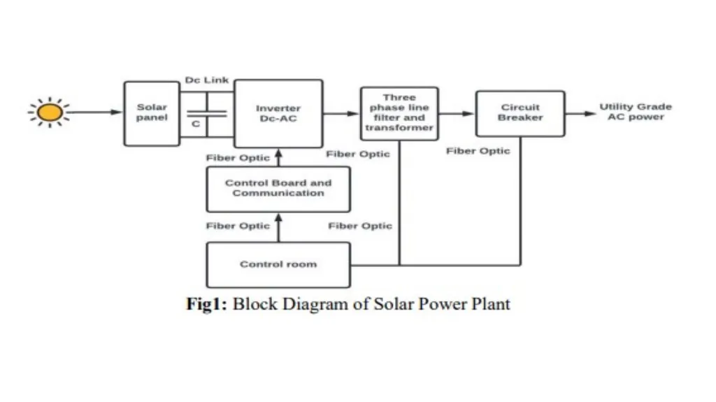
Solar photovoltaic (PV) systems are one of the most common types of DG systems. Solar PV panels convert sunlight into electricity, which can then be used to power homes and businesses.<br>
Solar photovoltaic (PV) systems are one of the most common types of DG systems. Solar PV panels convert sunlight into electricity, which can then be used to power homes and businesses.<br>
08
Wind Turbines
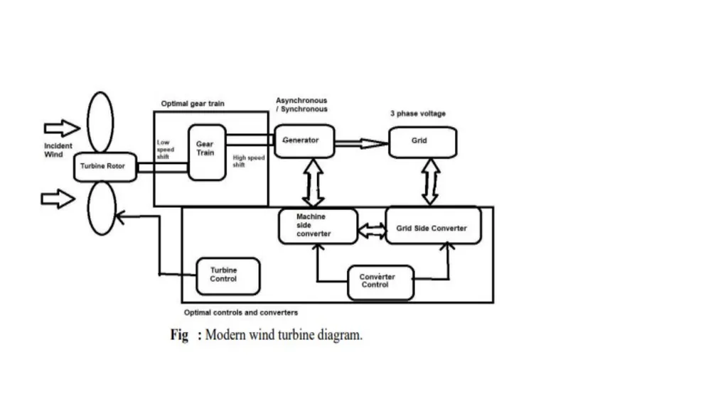
Wind turbines are another type of DG system that can be used to generate electricity. Wind turbines work by spinning blades in the wind, which turns a generator to produce electricity.<br>
Wind turbines are another type of DG system that can be used to generate electricity. Wind turbines work by spinning blades in the wind, which turns a generator to produce electricity.<br>
09
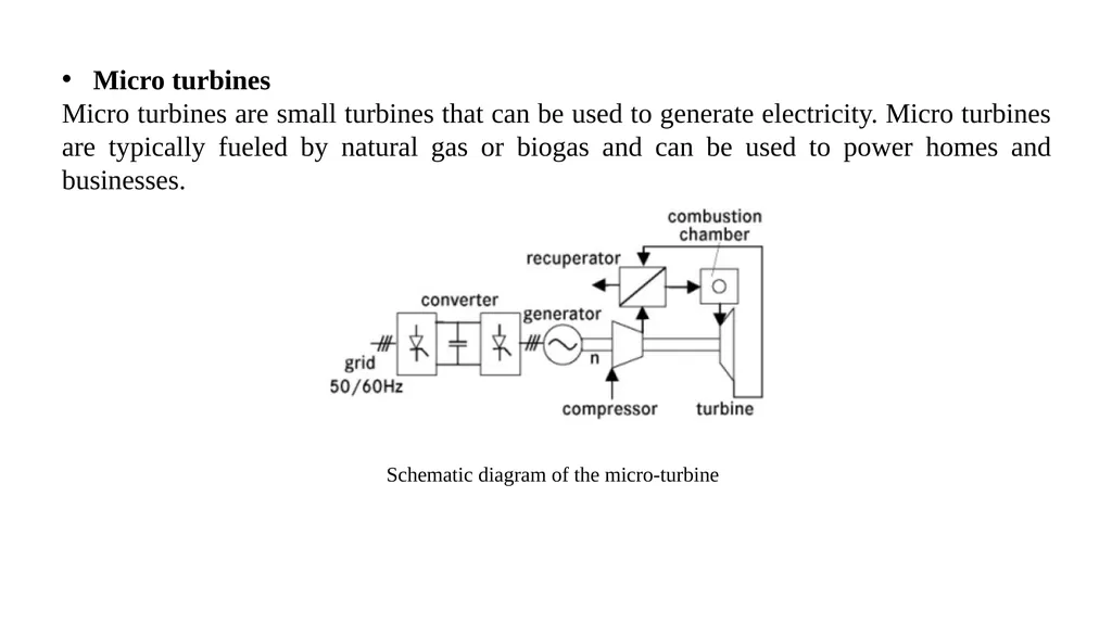
Schematic diagram of the micro-turbine Micro turbines
Micro turbines are small turbines that can be used to generate electricity. Micro turbines are typically fueled by natural gas or biogas and can be used to power homes and businesses.<br>
Micro turbines are small turbines that can be used to generate electricity. Micro turbines are typically fueled by natural gas or biogas and can be used to power homes and businesses.<br>
10
Combined Heat and Power (CHP)
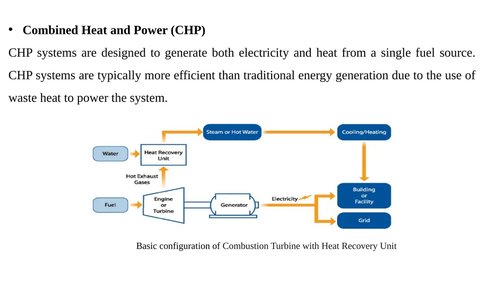
CHP systems are designed to generate both electricity and heat from a single fuel source. CHP systems are typically more efficient than traditional energy generation due to the use of waste heat to power the system. Basic configuration of Combustion Turbine with Heat Recovery Unit<br>
CHP systems are designed to generate both electricity and heat from a single fuel source. CHP systems are typically more efficient than traditional energy generation due to the use of waste heat to power the system. Basic configuration of Combustion Turbine with Heat Recovery Unit<br>
11
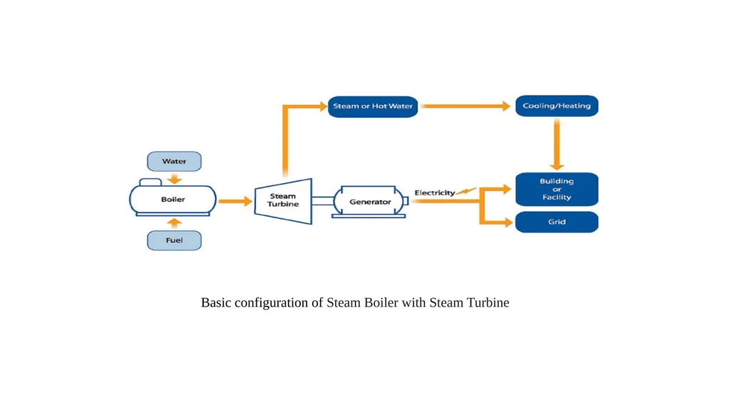
Basic configuration of Steam Boiler with Steam Turbine<br>
12
A CHP power plant can deliver multiple benefits and advantages compared to conventional energy production:
(i)Increased efficiency: CHP produces both electricity and heat and does so using less fuel compared to other energy plants. Plus, it captures heat and steam to generate additional power, further lowering the need for fuel.
(ii) Reduced emissions: Because CHP systems burn less fuel, they can reduce emission of greenhouse gases and other air pollutants.<br>
(i)Increased efficiency: CHP produces both electricity and heat and does so using less fuel compared to other energy plants. Plus, it captures heat and steam to generate additional power, further lowering the need for fuel.
(ii) Reduced emissions: Because CHP systems burn less fuel, they can reduce emission of greenhouse gases and other air pollutants.<br>
13
Natural-gas-Fired Fuel Cells
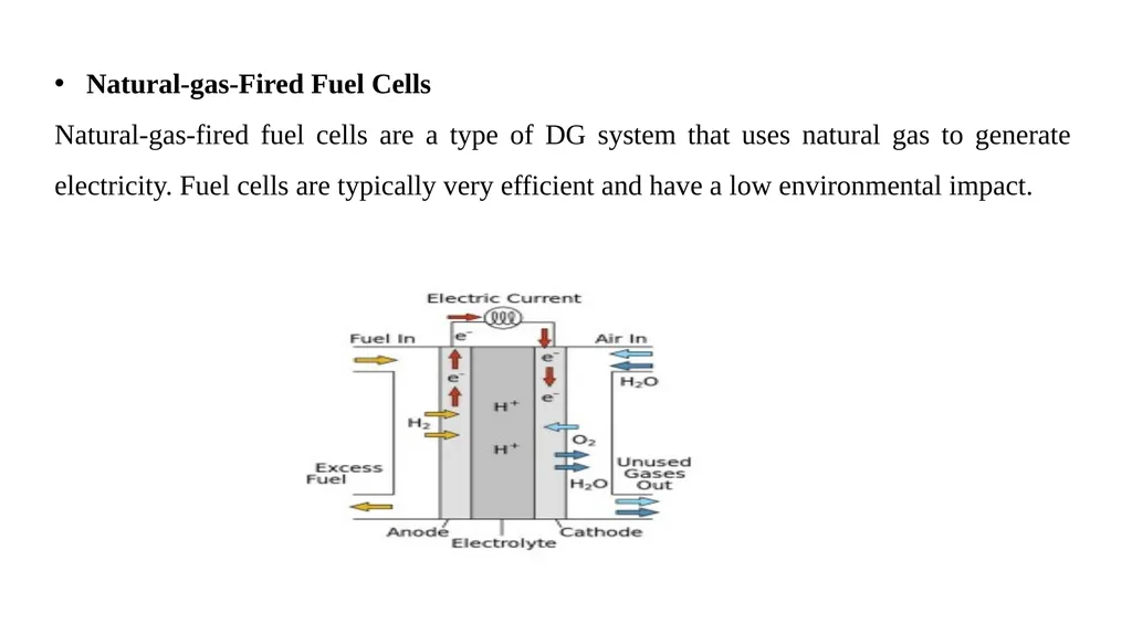
Natural-gas-fired fuel cells are a type of DG system that uses natural gas to generate electricity. Fuel cells are typically very efficient and have a low environmental impact.<br>
Natural-gas-fired fuel cells are a type of DG system that uses natural gas to generate electricity. Fuel cells are typically very efficient and have a low environmental impact.<br>
14
Fuel cells convert the chemical energy of a fuel directly to electrical energy by an electrochemical process.
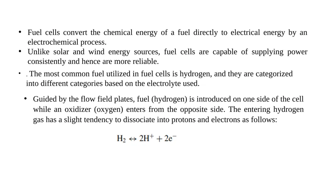
Unlike solar and wind energy sources, fuel cells are capable of supplying power consistently and hence are more reliable. . The most common fuel utilized in fuel cells is hydrogen, and they are categorized into different categories based on the electrolyte used. Guided by the flow field plates, fuel (hydrogen) is introduced on one side of the cell while an oxidizer (oxygen) enters from the opposite side. The entering hydrogen gas has a slight tendency to dissociate into protons and electrons as follows:<br>
Unlike solar and wind energy sources, fuel cells are capable of supplying power consistently and hence are more reliable. . The most common fuel utilized in fuel cells is hydrogen, and they are categorized into different categories based on the electrolyte used. Guided by the flow field plates, fuel (hydrogen) is introduced on one side of the cell while an oxidizer (oxygen) enters from the opposite side. The entering hydrogen gas has a slight tendency to dissociate into protons and electrons as follows:<br>
15
Emergency Backup Generators
Emergency backup generators are typically used to power homes and businesses in the event of a power outage. Backup generators can run on various fuel sources, including natural gas, propane, and diesel.<br>
Emergency backup generators are typically used to power homes and businesses in the event of a power outage. Backup generators can run on various fuel sources, including natural gas, propane, and diesel.<br>
16
Advantages and Disadvantages of DG
There are several advantages and disadvantages of DG, which include:
Advantages:
Reduced transmission and distribution losses
Improved grid stability and security
Reduced environmental impact
Increased efficiency Disadvantages:
Initial investment cost
Maintenance cost<br>
There are several advantages and disadvantages of DG, which include:
Advantages:
Reduced transmission and distribution losses
Improved grid stability and security
Reduced environmental impact
Increased efficiency Disadvantages:
Initial investment cost
Maintenance cost<br>
17
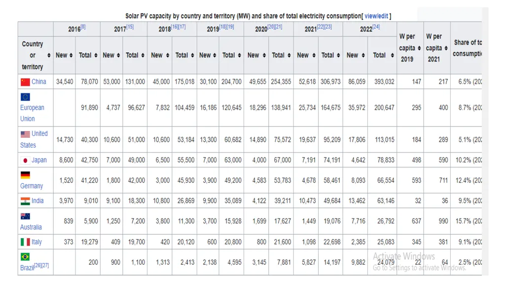
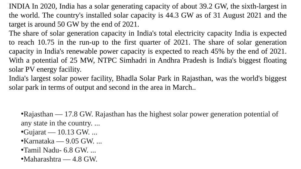
INDIA In 2020, India has a solar generating capacity of about 39.2 GW, the sixth-largest in the world. The country's installed solar capacity is 44.3 GW as of 31 August 2021 and the target is around 50 GW by the end of 2021.
The share of solar generation capacity in India's total electricity capacity India is expected to reach 10.75 in the run-up to the first quarter of 2021. The share of solar generation capacity in India's renewable power capacity is expected to reach 45% by the end of 2021. With a potential of 25 MW, NTPC Simhadri in Andhra Pradesh is India's biggest floating solar PV energy facility.
India's largest solar power facility, Bhadla Solar Park in Rajasthan, was the world's biggest solar park in terms of output and second in the area in March.. Rajasthan — 17.8 GW. Rajasthan has the highest solar power generation potential of any state in the country. ...
Gujarat — 10.13 GW. ...
Karnataka — 9.05 GW. ...
Tamil Nadu- 6.8 GW. ...
Maharashtra — 4.8 GW.<br>
The share of solar generation capacity in India's total electricity capacity India is expected to reach 10.75 in the run-up to the first quarter of 2021. The share of solar generation capacity in India's renewable power capacity is expected to reach 45% by the end of 2021. With a potential of 25 MW, NTPC Simhadri in Andhra Pradesh is India's biggest floating solar PV energy facility.
India's largest solar power facility, Bhadla Solar Park in Rajasthan, was the world's biggest solar park in terms of output and second in the area in March.. Rajasthan — 17.8 GW. Rajasthan has the highest solar power generation potential of any state in the country. ...
Gujarat — 10.13 GW. ...
Karnataka — 9.05 GW. ...
Tamil Nadu- 6.8 GW. ...
Maharashtra — 4.8 GW.<br>
18
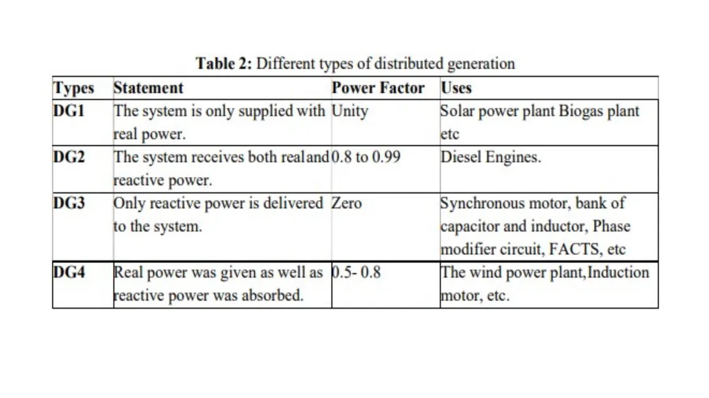
The distributed generations are basically real, and reactive power supported to distribution power system networks. The real and reactive power delivered to the system depends on the type of DGs are used. On the basis of real and reactive power delivery, the DGs are classified in four categories are as follows: DG1 (named as T1): DG1 only real power supported to system at unity power factor. For example, photovoltaic cell, solar systems, biogas, etc.
DG2 (named as T2): DG2 real and reactive power supported to system and operating at 0.80–0.99 leading power factors. For examples wind, tidal, wave, geo-thermal etc.
DG3 (named as T3): DG3 only reactive power supported for the system and operating at 0.00 power factor. For example, synchronous condenser, bank of inductor and bank of capacitors etc.
DG4 (named as T4): DG4 delivered reactive power to the system and absorb real power from system and operating at 0.80–0.99 lagging power factor. For example doubly fed induction generators based wind etc.<br>
DG2 (named as T2): DG2 real and reactive power supported to system and operating at 0.80–0.99 leading power factors. For examples wind, tidal, wave, geo-thermal etc.
DG3 (named as T3): DG3 only reactive power supported for the system and operating at 0.00 power factor. For example, synchronous condenser, bank of inductor and bank of capacitors etc.
DG4 (named as T4): DG4 delivered reactive power to the system and absorb real power from system and operating at 0.80–0.99 lagging power factor. For example doubly fed induction generators based wind etc.<br>
19
Besides the advantages, DG technology is also associated with some disadvantages if not installed at the optimal locations .
DG may lead to stability problems. Bidirectional power flow may lead to problems of protection. Furthermore, problems of frequency may occur along with islanding difficulties. Therefore, the following important issues and facts need to be considered visà-vis installation and sizing of DGs i. The types of DGs are a crucial factor to achieve optimal performance of the distribution system. The nature of injected power from DG units is exclusively depends upon type of DG is to be installed as requirement of load ii. The sizing and location parameters of DG have to be carefully determined to improve the overall performance and efficiency of the system technically.
iii. Evaluate the number and rating (size) of DGs to be placed in the power system for economic operation of the system. Since over size DG cause bidirectional power flow.<br>
DG may lead to stability problems. Bidirectional power flow may lead to problems of protection. Furthermore, problems of frequency may occur along with islanding difficulties. Therefore, the following important issues and facts need to be considered visà-vis installation and sizing of DGs i. The types of DGs are a crucial factor to achieve optimal performance of the distribution system. The nature of injected power from DG units is exclusively depends upon type of DG is to be installed as requirement of load ii. The sizing and location parameters of DG have to be carefully determined to improve the overall performance and efficiency of the system technically.
iii. Evaluate the number and rating (size) of DGs to be placed in the power system for economic operation of the system. Since over size DG cause bidirectional power flow.<br>
20
iv. Analyze the system security elements for carrying out continuous duty and maintain the appropriate indices (voltage profile index, power loss index, penetration level index and short-circuit level index) within acceptable limits Therefore, the installation of the DG becomes very crucial for reliable operation and to meet the demand of the consumers. Subsequently, these aspects need to be considered in detail for optimum sizing and siting of DG.<br>
21
The DG planning is a very important issue with installation of DG in all over world for delivering real and reactive power to the system.
The DG planning means the proper location and size as well as properly coordinated control of multiple DGs in the distribution power system networks.
The various combinations of DG planning as follows: (i) size only (ii) location only (iii) size and location (iv) size, location and numbers, (v) size, location, number and type.<br>
The DG planning means the proper location and size as well as properly coordinated control of multiple DGs in the distribution power system networks.
The various combinations of DG planning as follows: (i) size only (ii) location only (iii) size and location (iv) size, location and numbers, (v) size, location, number and type.<br>
22
The various advantages of optimal DG planning are as follows:
reduce real and reactive power loss
reduces power system oscillations
enhance power system stability, such as voltage, frequency and rotor angle stability
enhance power system reliability and security
enhance power system loadability
enhance available power transfer capacity
reduce power conjunction of line
increase band of operation of system hence system is more flexible operation.<br>
reduce real and reactive power loss
reduces power system oscillations
enhance power system stability, such as voltage, frequency and rotor angle stability
enhance power system reliability and security
enhance power system loadability
enhance available power transfer capacity
reduce power conjunction of line
increase band of operation of system hence system is more flexible operation.<br>
23
The DG planning are achieved by conventional and optimization techniques such as eigen-values, eigen-vector, modal index, residues, optimal power flow (OPF), sensitivity, linear programming (LP), nonlinear programming (NLP), mixed integer programming (MIP), ordinal optimization programming (OOP), dynamic programming (DYP), dual programming (DP) stochastic programming (SP) etc. The DG planning are also achieved by different artificial intelligence computational techniques such as genetic algorithm (GA), artificial neural network (ANN), fuzzy logic (FL), particle swarm optimization (PSO) technique, tabu-search (TS), simulated annealing (SA) algorithm, ant colony search (ACS), Monte Carlo algorithm (MCA), ant bee colony (ABC), hybrid techniques etc.<br>
24
Problem objectives
A general procedure and necessary steps need to be considered for optimum sizing and siting of DG units in distribution network.
Subsequently arrange the associated group of parameters in logical manner to form the objective function with suitable constraints.
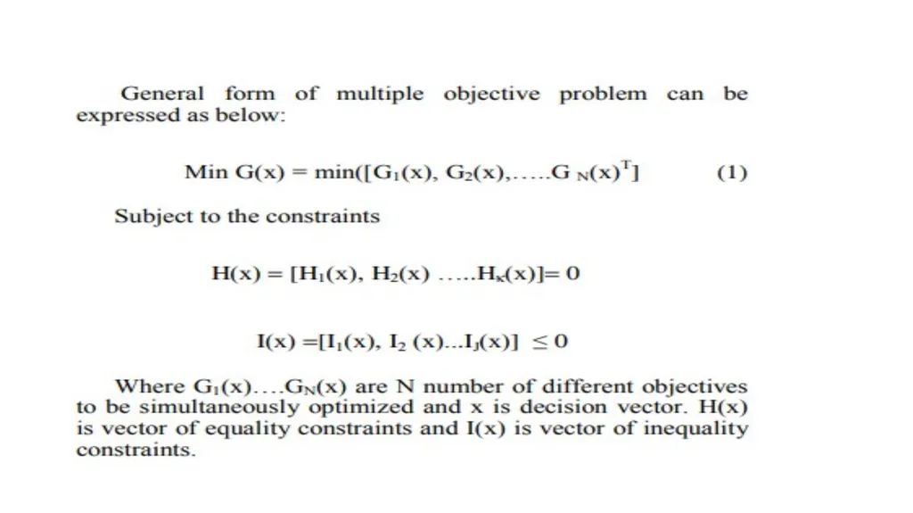
Define problem objective, it may be of single objective or multiobjective (the single objective functions are such as to minimize system power losses, system voltage profile improvement, cost minimization, improvement of system reliability, etc. and multiobjective function would be the combination of two or more single objective function) by considering suitable parameters and constitute the objective function, the objective function may be as follows<br>
A general procedure and necessary steps need to be considered for optimum sizing and siting of DG units in distribution network.
Subsequently arrange the associated group of parameters in logical manner to form the objective function with suitable constraints.
Define problem objective, it may be of single objective or multiobjective (the single objective functions are such as to minimize system power losses, system voltage profile improvement, cost minimization, improvement of system reliability, etc. and multiobjective function would be the combination of two or more single objective function) by considering suitable parameters and constitute the objective function, the objective function may be as follows<br>
25
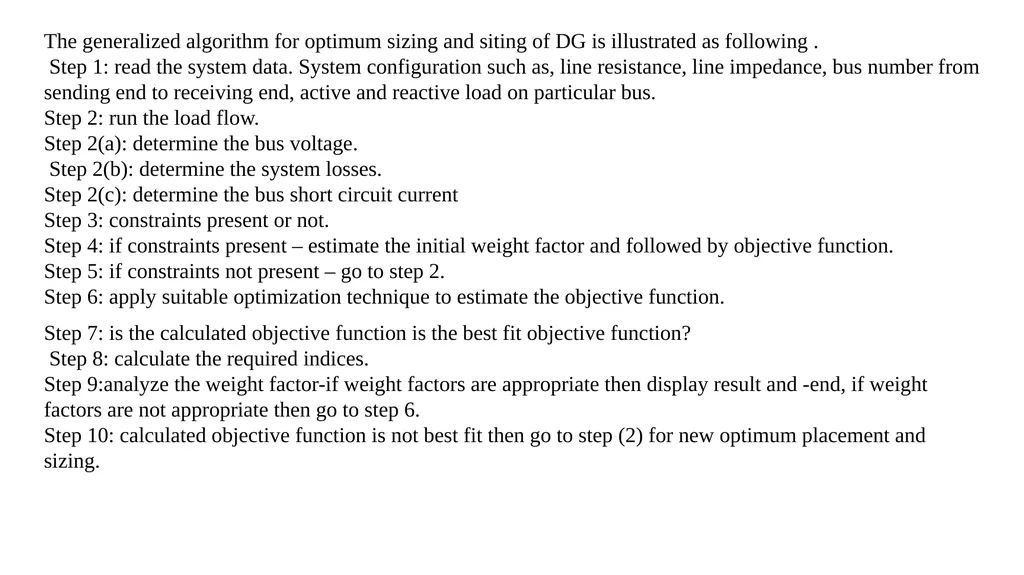
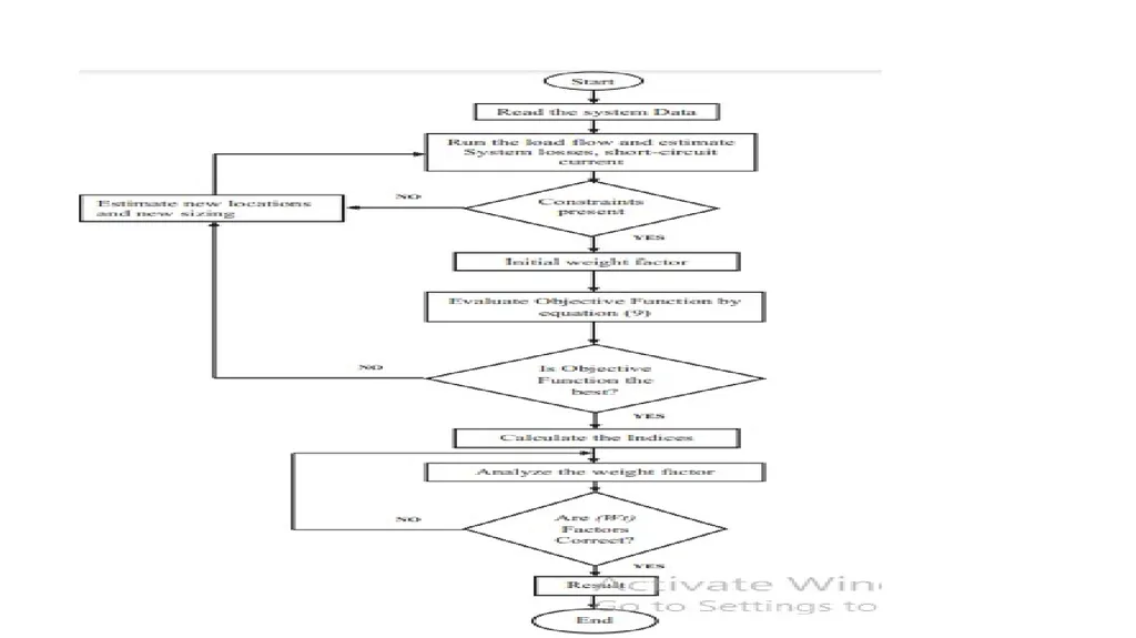
The generalized algorithm for optimum sizing and siting of DG is illustrated as following .
Step 1: read the system data. System configuration such as, line resistance, line impedance, bus number from sending end to receiving end, active and reactive load on particular bus.
Step 2: run the load flow.
Step 2(a): determine the bus voltage.
Step 2(b): determine the system losses.
Step 2(c): determine the bus short circuit current
Step 3: constraints present or not.
Step 4: if constraints present – estimate the initial weight factor and followed by objective function.
Step 5: if constraints not present – go to step 2.
Step 6: apply suitable optimization technique to estimate the objective function. Step 7: is the calculated objective function is the best fit objective function?
Step 8: calculate the required indices.
Step 9:analyze the weight factor-if weight factors are appropriate then display result and -end, if weight factors are not appropriate then go to step 6.
Step 10: calculated objective function is not best fit then go to step (2) for new optimum placement and sizing.<br>
Step 1: read the system data. System configuration such as, line resistance, line impedance, bus number from sending end to receiving end, active and reactive load on particular bus.
Step 2: run the load flow.
Step 2(a): determine the bus voltage.
Step 2(b): determine the system losses.
Step 2(c): determine the bus short circuit current
Step 3: constraints present or not.
Step 4: if constraints present – estimate the initial weight factor and followed by objective function.
Step 5: if constraints not present – go to step 2.
Step 6: apply suitable optimization technique to estimate the objective function. Step 7: is the calculated objective function is the best fit objective function?
Step 8: calculate the required indices.
Step 9:analyze the weight factor-if weight factors are appropriate then display result and -end, if weight factors are not appropriate then go to step 6.
Step 10: calculated objective function is not best fit then go to step (2) for new optimum placement and sizing.<br>
26
The penetration of the DER is growing day by day in the distribution system.
The aim of the distribution company (DISCOM) is to supply electric power with reliability, safety and security duly maintaining desired power quality indicators. At the same time the operational constraints viz. voltage, current and reactive power etc. should also be met with minimum loss.
If due care is not taken then introduction of DER may adversely affect the aims enumerated above.
The major challenges are:
Inaccurate voltage setting can result into the circulating currents if many small local DGs are being used
Large DG may change direction of power flow in the distribution system thus changing the voltage profile
The integration of DG changes the system state from passive to active and affects the reliability<br>
The aim of the distribution company (DISCOM) is to supply electric power with reliability, safety and security duly maintaining desired power quality indicators. At the same time the operational constraints viz. voltage, current and reactive power etc. should also be met with minimum loss.
If due care is not taken then introduction of DER may adversely affect the aims enumerated above.
The major challenges are:
Inaccurate voltage setting can result into the circulating currents if many small local DGs are being used
Large DG may change direction of power flow in the distribution system thus changing the voltage profile
The integration of DG changes the system state from passive to active and affects the reliability<br>
27
iv) It changes the fault current during unusual operation of the grid affecting protective system.
v) Islanding situation may deteriorate the reliability and system parameters like voltage and frequency.
vi) The maximum size of the DG is dependent on the interconnection location and the operational pf.
vii) There is a variation of the voltage profile with the change of location of the DG<br>
v) Islanding situation may deteriorate the reliability and system parameters like voltage and frequency.
vi) The maximum size of the DG is dependent on the interconnection location and the operational pf.
vii) There is a variation of the voltage profile with the change of location of the DG<br>
28
Objective function
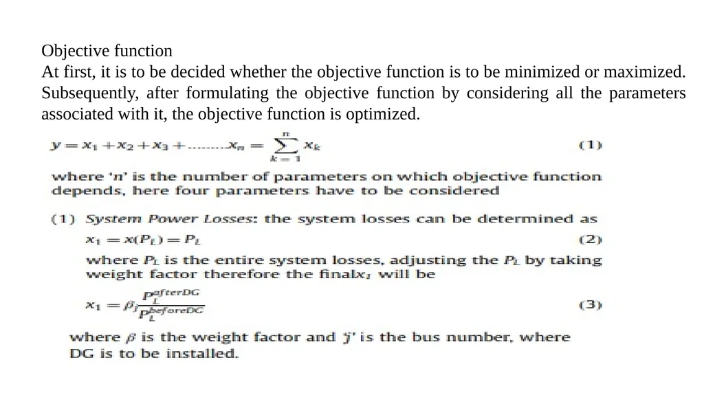
At first, it is to be decided whether the objective function is to be minimized or maximized. Subsequently, after formulating the objective function by considering all the parameters associated with it, the objective function is optimized.<br>
At first, it is to be decided whether the objective function is to be minimized or maximized. Subsequently, after formulating the objective function by considering all the parameters associated with it, the objective function is optimized.<br>
29
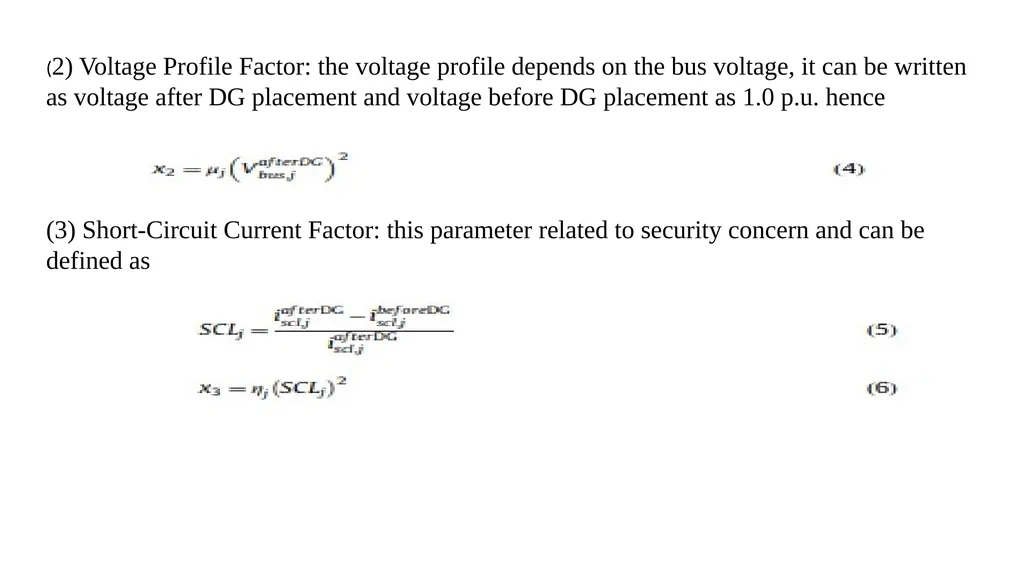
(2) Voltage Profile Factor: the voltage profile depends on the bus voltage, it can be written as voltage after DG placement and voltage before DG placement as 1.0 p.u. hence (3) Short-Circuit Current Factor: this parameter related to security concern and can be defined as<br>
30
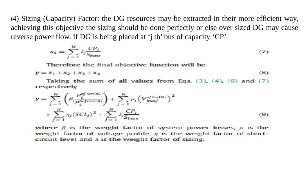
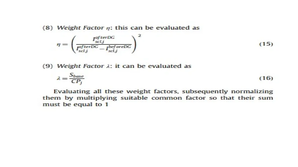
(4) Sizing (Capacity) Factor: the DG resources may be extracted in their more efficient way, achieving this objective the sizing should be done perfectly or else over sized DG may cause reverse power flow. If DG is being placed at ‘j th’ bus of capacity ‘CP’<br>
31
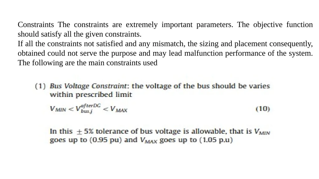
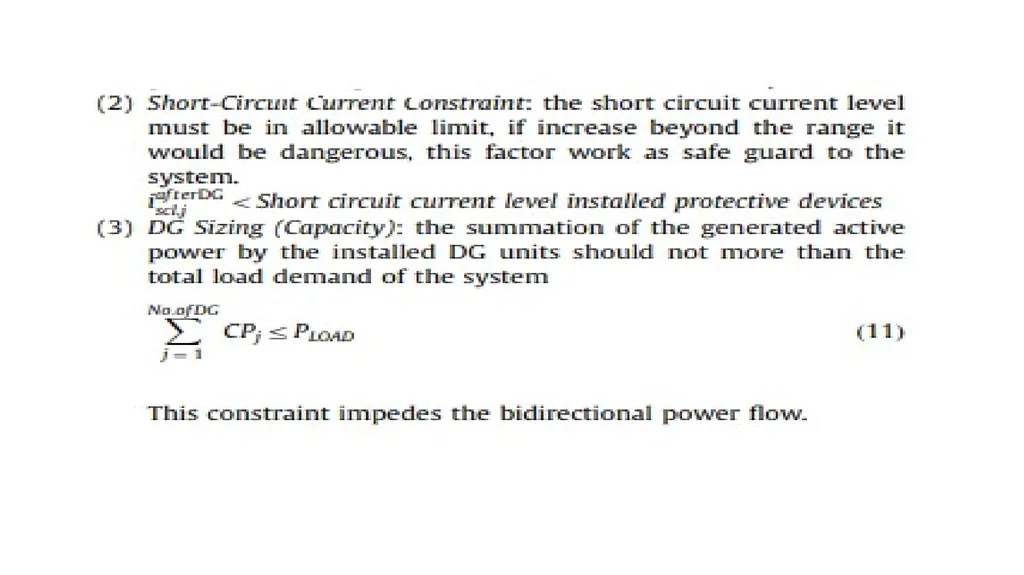
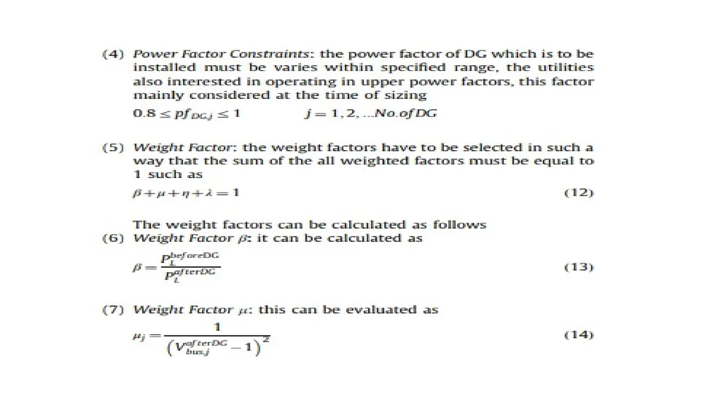
Constraints The constraints are extremely important parameters. The objective function should satisfy all the given constraints.
If all the constraints not satisfied and any mismatch, the sizing and placement consequently, obtained could not serve the purpose and may lead malfunction performance of the system. The following are the main constraints used<br>
If all the constraints not satisfied and any mismatch, the sizing and placement consequently, obtained could not serve the purpose and may lead malfunction performance of the system. The following are the main constraints used<br>
32
Required indices
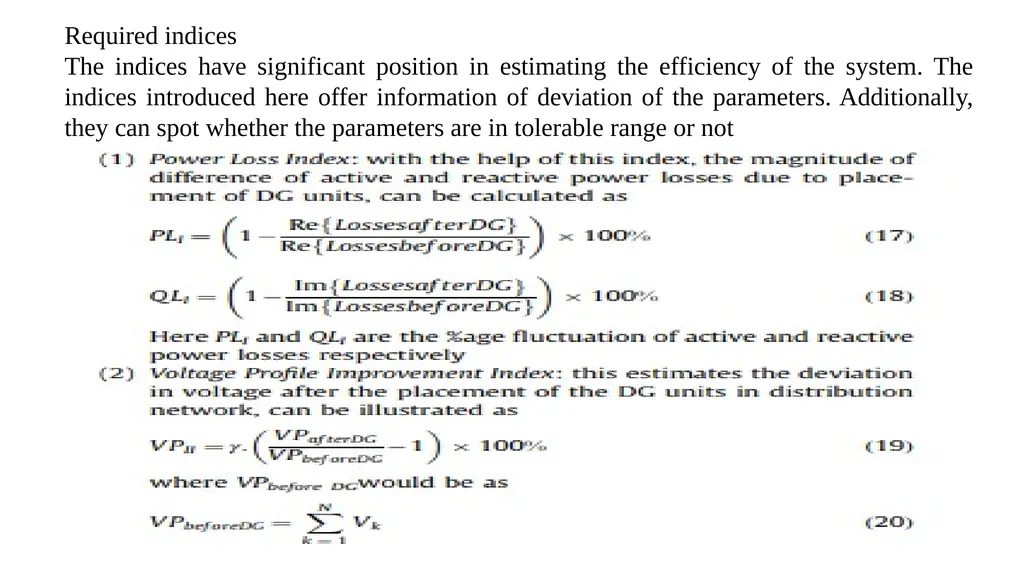
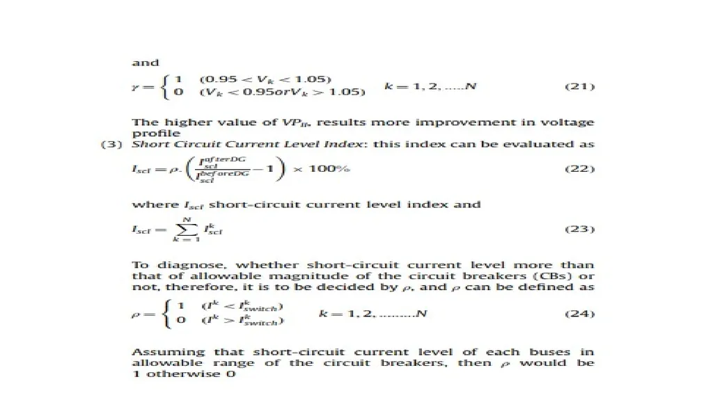
The indices have significant position in estimating the efficiency of the system. The indices introduced here offer information of deviation of the parameters. Additionally, they can spot whether the parameters are in tolerable range or not<br>
The indices have significant position in estimating the efficiency of the system. The indices introduced here offer information of deviation of the parameters. Additionally, they can spot whether the parameters are in tolerable range or not<br>
33
Types of DG Planning Methods
Distributed and dispersed generation can be studied in a variety of ways, each with different levels of detail, and each method focused on certain aspects of DG performance.
Generally, planners focus on two aspects of performance: cost and availability. Both can be studied with varying levels of detail. Cost is typically expressed in cost per kilowatt hour of power output ,but often the expected outgoing expense stream when and how what has to be spent is also important. Availability is typically expressed as percentage of time the unit is available. Outage time is the percent of time the DG unit is not available. Basic Cost Screening
DG "screening studies" are done to identify what types, sizes, and configurations of DG appear feasible and thus are worthy of more detailed study. Typically, these usually involve looking at the unit's performance only on an annual basis "the unit runs so many hours in the year and produces so many kWhr, with a peak of such and such kW.<br>
Distributed and dispersed generation can be studied in a variety of ways, each with different levels of detail, and each method focused on certain aspects of DG performance.
Generally, planners focus on two aspects of performance: cost and availability. Both can be studied with varying levels of detail. Cost is typically expressed in cost per kilowatt hour of power output ,but often the expected outgoing expense stream when and how what has to be spent is also important. Availability is typically expressed as percentage of time the unit is available. Outage time is the percent of time the DG unit is not available. Basic Cost Screening
DG "screening studies" are done to identify what types, sizes, and configurations of DG appear feasible and thus are worthy of more detailed study. Typically, these usually involve looking at the unit's performance only on an annual basis "the unit runs so many hours in the year and produces so many kWhr, with a peak of such and such kW.<br>
34
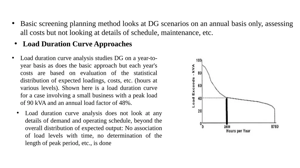
Basic screening planning method looks at DG scenarios on an annual basis only, assessing all costs but not looking at details of schedule, maintenance, etc. Load Duration Curve Approaches Load duration curve analysis studies DG on a year-to-year basis as does the basic approach but each year's costs are based on evaluation of the statistical distribution of expected loadings, costs, etc. (hours at various levels). Shown here is a load duration curve for a case involving a small business with a peak load of 90 kVA and an annual load factor of 48%. Load duration curve analysis does not look at any details of demand and operating schedule, beyond the overall distribution of expected output: No association of load levels with time, no determination of the length of peak period, etc., is done<br>
35
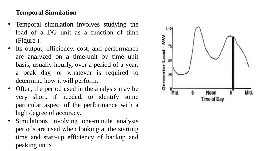
Temporal Simulation Temporal simulation involves studying the load of a DG unit as a function of time (Figure ).
Its output, efficiency, cost, and performance are analyzed on a time-unit by time unit basis, usually hourly, over a period of a year, a peak day, or whatever is required to determine how it will perform.
Often, the period used in the analysis may be very short, if needed, to identify some particular aspect of the performance with a high degree of accuracy.
Simulations involving one-minute analysis periods are used when looking at the starting time and start-up efficiency of backup and peaking units.<br>
Its output, efficiency, cost, and performance are analyzed on a time-unit by time unit basis, usually hourly, over a period of a year, a peak day, or whatever is required to determine how it will perform.
Often, the period used in the analysis may be very short, if needed, to identify some particular aspect of the performance with a high degree of accuracy.
Simulations involving one-minute analysis periods are used when looking at the starting time and start-up efficiency of backup and peaking units.<br>
36
Costs are characterized in two ways: depending on whether they are initial, or continuing costs, and depending on Whether they are fixed or variable costs Initial costs must be dealt with before a DG unit or energy resource can be used. For example, the DG unit, itself, must be obtained, a site must be prepared for it (foundation, sound abatement walls, etc.), fuel delivery systems installed, electrical connections made, etc. Costs associated with accomplishing all these tasks are the initial costs. Continuing costs are those associated with keeping the unit available and in service. These include taxes, annual inspections or certifications, fuel, repairs, labor costs for service personnel, etc. Usually, these are periodic monthly, annual, bi-annual, every five years, etc. expenses that continue as long as the unit is left in service.<br>
37
Fixed costs do not vary as a function of the amount or patterns of usage. The cost of the basic DG unit, itself, is usually a fixed cost: One must buy or lease the unit regardless of whether it is used every hour of every day, or not at all. Likewise, annually required inspections or certifications, as well as annual property taxes, are based off the value of the property, and are "fixed," even if they vary year-by-year, because the unit depreciates in value Variable costs are those that do vary as a function of the amount or type of usage. Fuel is a big component of variable cost: the more power produced, the more fuel used. Other variable costs include certain parts of O&M those that increase or change depending on the amount of usage.<br>