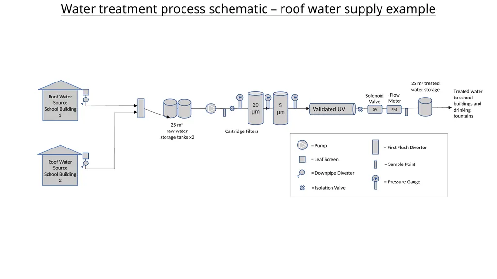
Water treatment process schematic roof water supply example Roof Water Source School Building 1 Roof Water Source School Building 2 25 m3 raw water storage tanks x2 25 m3 treated water storage 20 μm 5 μm Validated UV Cartridge Filters SV
"Water treatment process schematic – roof water" is the property of its rightful owner. Permission is granted to
download and print the materials on this website for personal, non-commercial use only, and to display it
on your personal computer provided you do not modify the materials and that you retain all copyright
notices contained in the materials. By downloading content from our website, you accept the terms of this
agreement.
Presentation Transcript
01
Water treatment process schematic – roof water supply example Roof Water Source
School Building 1 Roof Water Source
School Building 2 25 m3
raw water storage tanks x2 25 m3 treated water storage 20 μm 5
μm Validated UV Cartridge Filters SV FM Treated water to school buildings and drinking fountains Flow Meter Solenoid Valve = Leaf Screen = Pressure Gauge = Pump = Isolation Valve = Downpipe Diverter = First Flush Diverter = Sample Point<br>
02
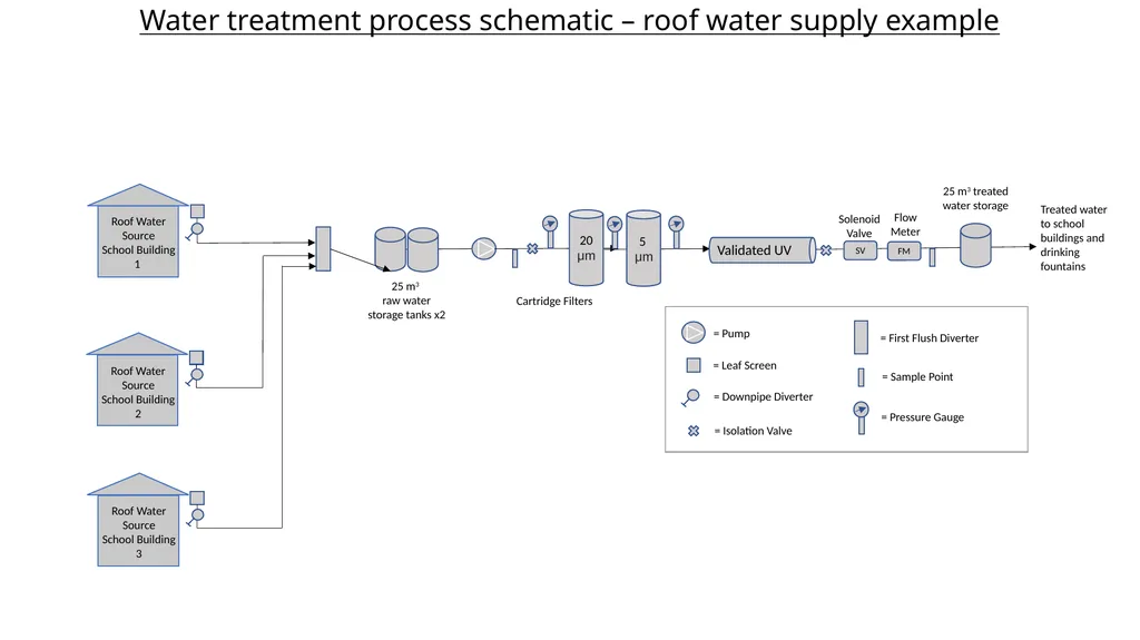
Water treatment process schematic – roof water supply example Roof Water Source
School Building 1 Roof Water Source
School Building 2 25 m3
raw water storage tanks x2 25 m3 treated water storage 20 μm 5
μm Validated UV Cartridge Filters SV FM Treated water to school buildings and drinking fountains Flow Meter Solenoid Valve = Leaf Screen = Pressure Gauge = Pump = Isolation Valve = Downpipe Diverter = First Flush Diverter = Sample Point Roof Water Source
School Building 3<br>
03
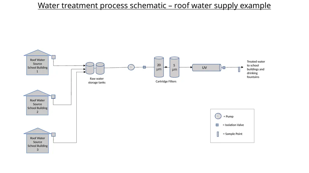
Water treatment process schematic – roof water supply example Roof Water Source
School Building 1 Roof Water Source
School Building 2 Raw water storage tanks 20 μm 5
μm UV Cartridge Filters Treated water to school buildings and drinking fountains = Pump = Isolation Valve = Sample Point Roof Water Source
School Building 3<br>
04
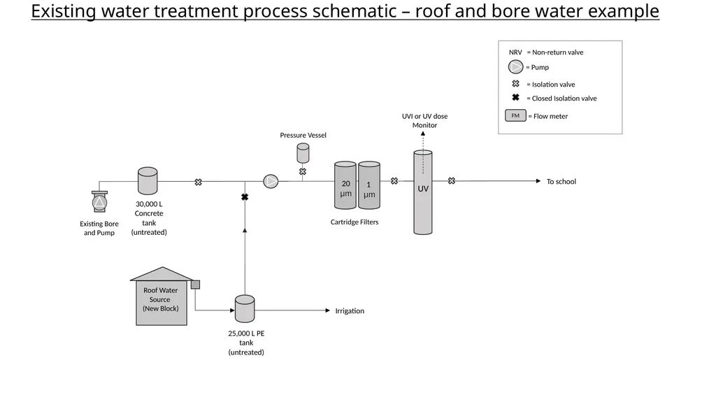
Existing Bore and Pump 25,000 L PE tank (untreated) Cartridge Filters 1
μm = Pump = Isolation valve UV UVI or UV dose Monitor To school NRV = Non-return valve Existing water treatment process schematic – roof and bore water example 20 μm 30,000 L Concrete tank (untreated) Roof Water Source
(New Block) Pressure Vessel FM = Flow meter = Closed Isolation valve Irrigation<br>
05
Existing Bore and Pump Cartridge Filters 1
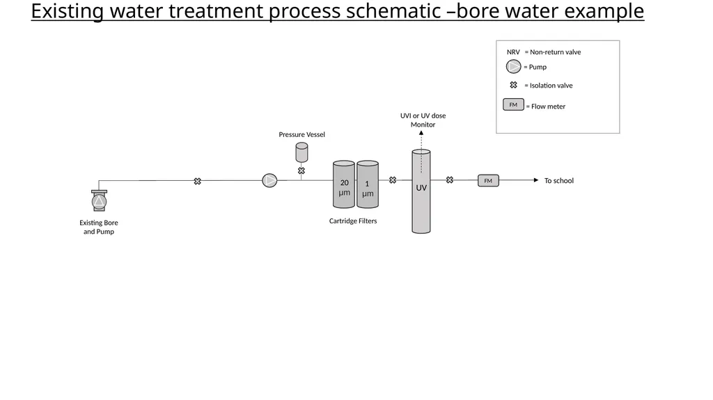
μm = Pump = Isolation valve UV UVI or UV dose Monitor To school NRV = Non-return valve Existing water treatment process schematic –bore water example 20 μm Pressure Vessel FM = Flow meter FM<br>
06
Existing Bore and Pump Cartridge Filters 1
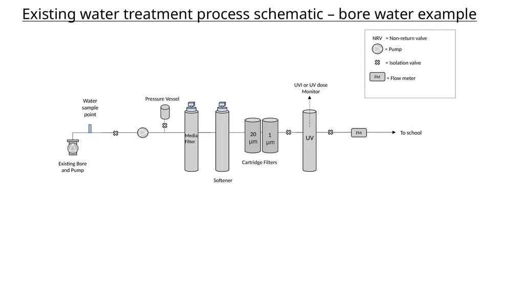
μm = Pump = Isolation valve UV UVI or UV dose Monitor To school NRV = Non-return valve Existing water treatment process schematic – bore water example 20 μm Pressure Vessel FM = Flow meter FM Media Filter Water sample point Softener<br>
07
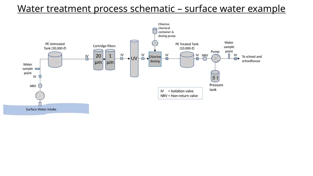
Water treatment process schematic – surface water example 20 μm NRV 1 μm Cartridge filters UV To school and schoolhouse IV IV IV Chlorine dosing Water sample point Water sample point IV = Isolation valve
NRV = Non-return valve IV IV PE Untreated Tank (30,000 ℓ) Pump Pressure tank 8 ℓ Chlorine chemical container & dosing pump Surface Water Intake PE Treated Tank (10,000 ℓ) NRV IV IV<br>