/
Technique GuideOVOMotion Technique GuideOVOMotion

Technique GuideOVOMotion - PDF document

willow
willow . @willow
Follow
345 views
Uploaded On 2020-11-24

Technique GuideOVOMotion - PPT Presentation

OVO OVOMotion InlayShoulder Arthroplasty Systems
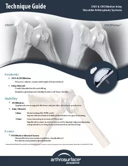
 Anatomic OVO OVOMotionPreserves volume version and height of humeral head Inlay GlenoidAvoids lateralization overstungMaintains glenohumeral st ID: 823270

component glenoid taper humeral glenoid component humeral taper trial implant shoulder bone guide articular post surface drill place advance

Share:

Link:

Embed:

Download Presentation from below link

Download Pdf The PPT/PDF document "Technique GuideOVOMotion" is the property of its rightful owner. Permission is granted to download and print the materials on this web site for personal, non-commercial use only, and to display it on your personal computer provided you do not modify the materials and that you retain all copyright notices contained in the materials. By downloading content from our website, you accept the terms of this agreement.


Presentation Transcript

Technique GuideOVOMotionOVO & OVOMotion
Technique GuideOVOMotionOVO & OVOMotion InlayShoulder Arthroplasty SystemsAnatomicOVO & OVOMotionPreserves volume, version and height of humeral headInlay GlenoidAvoids lateralization & overstungMaintains glenohumeral stability & native soft tissue tensionAccessOVOMotion Glenoid AccessHumeral head access reamer optimizes visualization of the inferior and posterior glenoid borderStabilityOVOMotionEpiphyseal crown supports the base and provides shear force protectionInlay Glenoid Inlay: No loosening after 4000 cyclesSuperior biomechanical stability and resistance to gross looseningOnlay: Gross loosening at a mean of 1126 cycles Signicant increase in contact forces on the implant edge predisposing components to rocking horse phenomenon and loosening1) Gagliano JR, Helms SM, Colbath GP, Przestrzelski BT, Hawkins RJ, DesJardins JD. A comparison of onlay versus inlay glenoid component loosening in total shoulder arthroplasty. J Shoulder Elbow Surg. 2017 Jul;

26(7):1113-1120.21. Beachchair positio
26(7):1113-1120.21. Beachchair position(tilt back to 45 degree angle).2. Short deltopectoral incision (from coracoid tip to pectoralis major insertion).3. This incision is utilitarian and can beconverted to an extensile approach ifnecessary.4. Develop skin aps over pectoralis& deltoid.5. Develop deltopectoral interval. a. The cephalic vein may go eithermedially or laterally. Lateral retraction of the cephalic vein can be benecial because it preserves the venous outow from the deltoid. b. Identify coracoid tip. c. Identify pectoralis major insertion.6.Release subdeltoid and subacromialadhesions. Abducting the shoulder in order to relax the deltoid facilitates this step.7.Retract the deltoid and pectoralis majormuscles. This step is facilitated by the use of a blunt, multi-pronged self-retaining retractor.8.Identify and develop the lateral border of the conjoined tendon. This step is assisted by exion of the shoulder, which relaxes the conjoined

tendon & facilitates exposure.9.Retract
tendon & facilitates exposure.9.Retract the conjoined tendon medially. Take care to not injure the musculo- cutaneous nerve. A blunt, non self-retaining retractor under the conjoined tendon facilitates exposure while minimizing risk to the nerve.10. Remove bursa from atop the subscapularisinsertion.11. Identify the anterior humeral circumexvessels, which dene the inferior aspect ofthe subscapularis. As needed, a 90 degreepediatric clamp is a useful tool to isolate the vessels. If necessary, a suture can be used to ligate the vessels.12. Identify and protect axillary nerve. The axillary nerve lies deep to the anteriorhumeral circumex vessels and supercial to the subscapularis muscle at the level of the glenoid. A rubber vessel loop can be used to protect/isolate the axillary nerve, if necessary.13. Incise the subscapularis. Use of a needle tip electrocautery 1 cm lateral to themusculotendinous junction facilitatesthis step. a. Patients with anterior-inferi

or instability may be candidates for
or instability may be candidates for capsular shift and/or Bankart repair. In such cases, begin the subscapularis incision inferiorly and proceed superiorly in order to best dierentiate the tendon from the underlying capsule. b. Alternatively, the subscapularis and capsule can be incised in one layer.c.Alternatively, the lesser tuberosity may be osteotomized with a sharp, 1 inch straight osteotome. This will allow bone to bone healing at the conclusion of the procedure.Anterior Deltopectoral Approach314. Place #2 sutures using a Mason-Allenconguration into the edge of thesubscapularis to help retract the tendonand for denitive repair at the conclusionof the procedure.a.A medium Cobb elevator and/or Metzenbaum scissors help to bluntly develop the layer between the subscapularis and the joint capsule. It is important to separate the to the joint line in order to address (if necessary) a Bankart lesion.15. Release the

rotator interval capsulebetween the uppe
rotator interval capsulebetween the upper border of thesubscapularis and the anterior edgeof the supraspinatus.16. Incise the glenohumeral joint capsule along the anatomic neck with electrocautery.17. If necessary, place a blunt CobraŽ or Hohman retractor between the axillary nerve and subscapularis/capsule in order to protect the axillary nerve.18. Release the glenohumeral capsule from itsinsertion on the anatomic neck of the humerus anteriorly and inferiorly. External rotation and exion of the shoulderfacilitates capsular release and improves humeral head exposure.19. Release the capsule completely o theanatomic neck until adequate exposure ofthe humeral head defect is achieved.20. Place a humeral head retractor (i.e. Fukuda) to evaluate the glenoid and check for a Bankart lesion.21. Perform the implantation of the OVOMotion’ Shoulder Arthroplasty System components as indicated.22. Repair glenohumeral joint capsule andsubscapularis as indicated.23. Closu

re utilizing accepted practices.ason-A
re utilizing accepted practices.ason-Ane of thect the tendonthe conclusionator and/help to bluntlyween thee joint capsule. arate thee capsule medialer to address (if esion4Shoulder ArthroplastySystemChapter One: 5The OVOMotion’ Shoulder Arthroplasty System includes:1. Humeral articular component and a taper post xation component that mate together via a taper interlock to provide stable and immobile xation of the implant and stress bearing contact at the bone/prosthetic interface;2. Glenoid component intended to articulate with the humeral component when both articular surfaces of the shoulder joint are aected.The enclosed humeral articular component may be used with an appropriate Arthrosurface glenoid component (sold separately).MaterialsArticular Component: Cobalt-Chronium Alloy (Co-Cr-Mo)Undersurface Coating: Titanium (CPTi)Taper Post: Titanium Alloy (Ti-6Al-4V) IndicationsFor the reconstruction of painful an

d/or severely disabled shoulder joints r
d/or severely disabled shoulder joints resulting from post-traumatic degenerative disease or avascular necrosis. The humeral head and neck and glenoid vault should be of sucient bone stock to support loading. The rotator cu should be intact or reconstructable.The device is a single-use implant intended to be used for hemiarthroplasty or in conjunction with the Arthrosurface glenoid component for total shoulder arthroplasty. Both humeral and glenoid components of the OVOMotion’ Shoulder Arthroplasty System are intended for cemented use only.OVOMotion’ System Components€ Cobalt Chrome Component (Ovoid shapes, 7 oset choices)€ Ti Plasma Spray Undercoating€ Morse Taper: Interlocks the two components€ Titanium Fixation Component (Cannulated, Bead blasted)OVOMotion Shoulder Arthroplasty SystemChapter One: OVOMotion Shoulder Arthroplasty System6Remove osteophytes around the humeral head using a 3/4 inch osteotome and/or rongeur. There should be a smooth transition fro

m the humeral neck to the humeral head.2
m the humeral neck to the humeral head.2. Place the appropriate Mapping Templates over the articular surface and map the surface in both superior/inferior and anterior/posterior planes. Utilize Templatesto obtain the superior/ inferior diameter and anterior/posterior diameter that best replicate the anatomy. Use the sizing card to record the diameters. The Surface Reamer will be selected based on the anterior/posterior value. Place the Surface Reamer onto the humeral head to verify the Surface Reamer size and placement.3. Utilizing the Surface Reamerguide, advance the 2.5mm Guide Pin into the bone using a Cannulated Powered Drill. Advance Guide Pin into bone until lateral humeral cortex is reached, with care to avoid penetrating through the lateral humeral cortex. Start all Reamers and Drills o of the surface of the bone to avoid chipping.Surgical Technique Chapter One: OVOMotion Shoulder Arthroplasty System4. Using a powered drill, advance the Centering Shaft over

Guide Pin until the depth shoulder mark
Guide Pin until the depth shoulder marking is at the height of the articular surface. The Centering Shaftbe placed slightly proud of the surface to compensate for surface attening of the humeral head. The shoulder of Centering Shaft represents the location of the crown 5. Using the Surface Reamer that matches the anterior/posterior value, advance Surface Reamer over Centering Shaft until it reaches the stop on the Centering Shaft6. a) Repeat using the Access Reamer. Advance Access over Centering Shaft until it reaches the stop on Centering Shaftb) Or if preferred, utilize the Sagittal Guide to locate the sagittal saw cutting plane. Be sure all are started before engaging the humeral head.If performing the Inlay Glenoid GRS System proceed to Chapter Three prior to proceeding to next step. Refer to GRS Component label to select appropriate glenoid implant for use with the humeral component.88. With the Preparation Trial xed in place, insert the Pilot Drill th

rough the center of the and advance unti
rough the center of the and advance until the laser mark indicated on the Pilot Drillof the handle. Leave Pilot Drill in place and unscrew and remove the 9 . Advance the Tap over the Pilot Drill Tap is even with the height Preparation Trial. Remove Tapand remove Pilot Drill. Prior to inserting the Taper Post, thoroughly cleanse the pilot hole of any debris and then inject the cement in a retrograde fashion from the end of the hole upwards. *Surgeon preference pending bone quality7. Assemble the onto the Preparation Trial and secure the Preparation Trial into position using the Short Guide PinsThe pins are critical to maintain the correct rk ae Pins. rect Laser Marktheght Taphe holen a le910. Load the Taper Post into the distal end of the to Preparation Trial. Place the Hex Driver through the and advance the Taper Postthe stop on the shaft of the Hex Driver comes in contact with the back of the stopon the shaft of thethe s

Hex Driver comes in tact with t
Hex Driver comes in tact with the back of the conte.11. Use the Alignment Gauge to ensure that the Taper Post is seated at the proper depth. The Alignment Gauge is inserted into the Preparation Trial. The Gauge should meet resistance from the Taper Post Preparation TrialIf the Gauge is sitting proud then leave it in place Hex Driver to rotate it until ush with the Trial. If the Alignment Gauge does not connect Taper PostTaper Postinserted too far into the bone. To address this situation, rotate the Taper Post counterclockwise and check placement with the Alignment GaugeChapter One: OVOMotion Shoulder Arthroplasty System1013. Firmly mallet the Impactor until the Humeral Articular Component is completely seated onto Taper Post12. Prior to placing the Humeral Articular Component Implant Holder make sure that sucient suction is present to hold the device onto the distal suction cup. Align the Humeral Articular ComponentImplant Holderthe etch mark in lin

e with the superior oset of the Humeral
e with the superior oset of the Humeral Articular Component. Use the Implant mark to align the implant in the proper orientation and insert onto taper of Taper PostMatching OVOMotion’ Implant Diameters to Appropriate GlenoidMore CurvedOVOMotion’ Diameters54 x 50Less Curvedl d onto sue deraet ompopeplantDiameterstoApure eviceal er with of the planter ost.propriate GlenoidpropriateGlenoidOVO® InstrumentationSystem Catalog (OVOMotion’)Instrumentation System8000-5000OVO Instrumentation Kit8000-5100OVOMotion Instrumentation KitTaper Post (Fixation Component)8156-0032-A12.0mm x 32mmIncludes 2.5mm guide wire, 2.0mmshort guide pins and taper cleaner8H00-0100Pin Kit, Shoulder, OVOCENTERINGSHAFTTEMPLATESREDUCTION TRIALS (7) & SIZING TRIALS (7)SPOTFACEHANDLEPILOTTAPGAUGESUCTIONIMPACTORHEXDRIVEROvo Humeral Articular Components8HM2-464246mm x 42mm Oset8HM2-484448mm x 44mm Oset8HM2-504650mm x 46mm Oset8HM2-524852mm x 48m

m Oset8HM2-545054mm x 50mm Oset8HM2-56
m Oset8HM2-545054mm x 50mm Oset8HM2-565256mm x 52mm Oset8HM2-585458mm x 54mm OsetOVOMotion’ InstrumentationACCESS REAMERSAGITTAL GUIDESADAPTER,QUICK CONNECT (2)SHAFT (2)PREPARATIONChapter One: OVOMotion Shoulder Arthroplasty System12Shoulder ArthroplastySystemChapter Two: ®13The OVO Contoured Articular Prosthetic incorporates an articular component and a taper post component that mate together via a morse taper interlock to provide stable and immobile fixation of the implant and stress bearing contact at the bone/prosthetic interface.MaterialsArticular Component: Cobalt-Chromium Alloy (Co-Cr-Mo)Undersurface Coating: Titanium (CPTi)Taper Post: Titanium Alloy (Ti-6Al-4V) IndicationsFor the reconstruction of painful and/or severely disabled shoulder joints resulting from post-traumatic degenerative disease or avascular necrosis. The humeral head and neck should be of sucient bone stock to support loading. The rotator cu should be intact or recons

tructable. The device is a single-use im
tructable. The device is a single-use implant intended to be used with bone cement. System Components€ Cobalt Chrome Component(Ovoid shapes, 7 oset choices)€ Ti Plasma Spray Undercoating€ Morse Taper:Interlocks the two components€ Titanium Fixation Component(Cannulated, Bead blasted)Chapter One Shoulder Arthroplasty SystemChapter Two: OVO Shoulder Arthroplasty System14Remove all osteophytes around the humeral head using a 3/4 inch osteotome and/or rongeur. There should be a smooth transition from the humeral neck to the humeral head. Use the Reduction Trial to ascertain that all osteophytes have been adequately removed.2. Place the appropriate Mapping Templates over the articular surface and map the surface in both superior/inferior and anterior/posterior planes. Utilize the Templates to obtain the superior/inferior diameter and anterior/posterior diameter that best replicate the anatomy. Use the Sizing Card to record the diameters. The Surface Reamer will be sel

ected based on the anterior/posterior va
ected based on the anterior/posterior value. Place the Reduction Trial onto the humeral head to verify the Reduction Trial size and placement. Note: The Surface Reamerbe used to assess correct pin location.3. Locate the Guide Pinbelow). Place the 2.5 mm Guide Pin into a cannulated powered drill and secure at the etch marking on the Guide Pin. Advance the Guide Pin into the bone with care to avoid penetrating through the lateral humeral cortex.Surgical Technique23Drill GuideReduction TrialShaft & Reamerd usingd be aumera154. Using a cannulated powered drill, advance the Centering Shaft over the Guide PinCentering Shaft marking is at the height of the articular surface. The Centering Shaft can be placed slightly proud to the surface to compensate for a attened humeral head. The shoulder of the Centering Shaft height representing the location of the crown of the 5. Using the OVO Reamer that matches the anterior/posterior value, advance the OVO Reamer ove

r the Centering Shaft until it reaches t
r the Centering Shaft until it reaches the stop on the Centering Shaft. If using an Inlay Glenoid Componentrepeat using the Crown Reamer to provide additional access for the instruments. Be sure the OVO is started before engaging the humeral head.6. Place the appropriate Reduction Trial onto the prepared humeral surface and perform a range of motion evaluation. Assemble the onto the Preparation Trial and secure the Preparation Trial into position using at least two Short Guide Pins. The pins are critical, keeping the trial stable so that the correct orientation of the nal implant can be maintained.Chapter Two: OVO Shoulder Arthroplasty System168. Advance the over the Pilot Drilluntil the proximal shoulder of the even with the height marker on the Preparation Trial collar.9 . Advance the Tap over the Pilot DrillTap is even with the height Preparation Trial collar. Remove TapPilot Drill*Surgeon preference pending bone quality7. With the Preparation Trial xed in

place, insert the Pilot Drill through t
place, insert the Pilot Drill through the center of the and advance until the laser mark indicated on the Pilot Drillhandle. Leave the Pilot Drill in place and unscrew and remove the Laser MarkPreparationTrial CollarLaser Mark17Chapter Two: OVO Shoulder Arthroplasty System11. Use the Alignment Gauge to ensure that the Taper Post is seated at the proper depth. The Alignment Gauge is inserted into the Preparation Trial. TheGauge should meet resistance from the Taper PostPreparation TrialIf the Gauge is sitting proud then leave it in place Hex Driver to rotate it ush with the Trial. If the Alignment Gauge does not connect Taper Post Taper Postinserted too far into the bone. To address this situation, rotate the Taper Post counterclockwise and check placement with the Alignment GaugePlace the Reduction Trial into the defect that matches the oset prole of the chosen OVO Articular Component. Conrm the t of the Reduction Trial so that it is congruent with the edg

e of the surrounding articular surface o
e of the surrounding articular surface or slightly recessed. If the Reduction Trial is proud at the edge of the articular cartilage, re-ream the area until the Reduction Trial is ush or slightly recessed. IF PERFORMING THE GLENOID: Proceed to Step 1 in Chapter Three10. Prior to inserting the Taper Post, thoroughly cleanse the pilot hole of any debris and inject the cement in a retrograde fashion from the end of the hole upwards. Load the Taper Post into the distal to the Preparation Trial. Place the Hex Driver through the and advance the Taper Post until the stop in the shaft of the Hex Driver comes in contact with the back of the . Be careful NOT to advance the screwdriver once it contacts the handle as it will move the screw in and away from the Morse Taper1813. Firmly mallet the ImpactorOVO Component is completely seated onto the Taper Post12. Prior to placing the OVO ComponentImplant Holder, make sure that sucient suction is present to hold the device onto

the distal suction cup. Align the OVO Co
the distal suction cup. Align the OVO ComponentImplant with the etch mark inline with the superior oset of the OVO Component. Use the Implant mark to align the implant in the proper orientation and insert onto the taper of the Taper PostMatching OVO Implant Diameters to Appropriate Glenoid48 x 44More Curved Diameters54 x 50Less CurvedotrioterDiameterstoApproprin on or rateGlenoid InstrumentationSystem Catalog (OVO)Instrumentation System8000-5000OVO Instrumentation KitTaper Post (Fixation Component)8156-0032-A12.0mm x 32mmincludes 2.5mm guide wire, 2.0mmshort guide pins and taper cleaner8156-0032-W15.6mm x 32mmincludes 2.5mm guide wire, 2.0mmshort guide pins and taper cleanerSHAFTTEMPLATESREDUCTION TRIALS (7) & SIZING TRIALS (7)SPOTFACEHANDLEPILOTTAPGAUGESUCTIONIMPACTORHEXDRIVEROvo Humeral Articular Components8H02-464246mm x 42mm Oset8H02-484448mm x 44mm Oset8H02-504650mm x 46mm Oset8H02-524852mm x 48mm Oset8H02-545054mm x 50m

m Oset8H02-565256mm x 52mm Oset8H02-58
m Oset8H02-565256mm x 52mm Oset8H02-585458mm x 54mm OsetUpper TrayLower TrayChapter Two: OVO Shoulder Arthroplasty System20Inlay GlenoidChapter Three: 21The Inlayglenoid component is intended to interface and articulate with the humeral component when both articular surfaces of the joint are aected.MaterialsGlenoid Component: Ultra High Molecular Weight Polyethylene (UHMWPE)IndicationsFor the reconstruction of painful and/or severely disabled shoulder joints resulting from post-traumatic degenerative disease or avascular necrosis. The humeral head and neck should be sucient bone stock to support loading. The rotator cu should be intact or reconstructible. The device is a single-use implant intended to be used with bone cement. Inlay Glenoid System Components€ Ultra High Molecular Weight Polyethylene (UHMWPE)€ Inlay design€ Labrum preserving€ Two oset choices per componentSinglePartial Glenoid ComponentDoubleFull Glenoid ComponentInlay Glenoid

ReplacementChapter Three: Inlay Glenoid
ReplacementChapter Three: Inlay GlenoidSurgical TechniqueUse the to locate the intended implant position on the glenoid surface. Position the central to the inferior aspect of the glenoid lesion. Place the tip of the Guide Pin into the and advance the Guide Pininto the bone to the depth of the single etch mark using a cannulated power drill. The Guide Pinslightly oset posteriorly. This is normal for the system as the begins to cut anterior rst.2. Introduce the Inferior Glenoid Reamer over the Pin and carefully advance under power until the Inferior depth stop makes contact with the proximal end of the Guide Pin. Be sure to ream and visually check the depth of the reamer using the Inferior Glenoid Trial.º approach for spherical reamingºAngled approach & ream creates a spherical socketChapter Three: Inlay GlenoidFlexible Peg Drill3. With the Inferior Glenoid Trial in place over the Pin, conrm that the trial is ush or slightly recessed t

o the remaining glenoid fossa. Position
o the remaining glenoid fossa. Position the Inferior Glenoid Trial and place the Flexible Peg Drill into the central hole. Advance the Flexible Peg Drill to the stop to make the tunnel for the peg of the ComponentDo not allow the Flexible Peg Drill to engage with any other hardware. Do not run the Flexible Peg in reverse. These actions can cause the Flexible Peg Drill to break.*If using the Single Glenoid Component only, proceed to Step 74. If using the larger Double Glenoid Implant, place the Inferior Glenoid Trial in its proper orientation. Advance Guide Pin into the superior hole of the Inferior Glenoid Trial and drill to the proximal line of the double etch mark using a cannulated powered drill.5. a) Introduce the over the Guide Pin and carefully advance under power until the depth stop makes contact with the proximal end of the Guide Pin. Be sure to ream carefully and visually check the depth of the reamer Double Glenoid Trialb) Position the Double Glenoid T

rial and conrm that Double Glenoid Tria
rial and conrm that Double Glenoid Trial is ush or slightly recessed to the remaining glenoid fossae m o 5b.247. Use the Angled Gouge and mallet to create several small cement channels around the periphery of the glenoid fossa to aid with cement xation.8 . Apply a small amount of low-viscosity bone cement into the prepared glenoid surface. Using Cement Finger Cap, apply pressure to the cement in the glenoid fossa to make sure the cement lls the peg holes and gouge channels.9 . Place the Inlay Glenoid Implant into position Glenoid Impactor to secure the glenoid implant into position making sure the implant ts ush or slightly recessed to the surrounding glenoid fossa. The Impactor is created by sliding the Impactor Tip over the end of the Angled Gouge. Maintain rm pressure on the implant until the bone cement sets. Remove any excess bone cement.Angled GougeCement Finger CapTipAngled GougeImpactor6. With the Double Glenoid Trial in position, advance

Flexible Peg Drill into both central hol
Flexible Peg Drill into both central holes of theDouble Glenoid Trial to make bone tunnels for the Double Glenoid Component pegs.Inlay Glenoid Replacement InstrumentationSystem CatalogFINGER CAPUNIVERSALINSTRUMENT HANDLEETCHEDGUIDEWIREINFERIORGOUGEFLEXIBLEPEG DRILLETCHEDGUIDEWIREInlay Glenoid Instrumentation SystemG007-14002.0mm Glenoid Guide Pin (sterile)G000-0100Inferior Glenoid Instrument Kit (sterile, disposable)G000-0200Superior Glenoid Instrument Kit(sterile, disposable)G000-030015mm Reamer Pack, Glenoid(sterile, disposable)Inlay Glenoid ComponentInferior Glenoid Component - SingleG203-201019mm x 20mm Glenoid Comp. 1.0mm Oset(58-54mm)G203-201519mm x 20mm Glenoid Comp. 1.5mm Oset(52-46mm)Superior Glenoid Component - DoubleG203-251520mm x 25mm Glenoid Comp. 1.0mm Oset(58-54mm)G203-252020mm x 25mm Glenoid Comp. 1.5mm Oset(52-46mm)Matching Ovo Inferior TraySuperior TrayREDUCTION TRIALS(Packaged sterile separately in disposable instrument boxwith sucti

on)DRILLGUIDEGUIDES(L,R)REDUCTION TRI
on)DRILLGUIDEGUIDES(L,R)REDUCTION TRIALSIMPACTORChapter Three: Inlay Glenoid26AsymmetricalOVOMotionArthrosurface Shoulder SystemsInlayWarningsImproper selection, placement, positioning, alignment, and xation of the implant components may reduce the service life of the prosthetic components. Inadequate preparation and cleaning of the implant components mating surfaces may result in improper xation of the device. Improper handling of the implants can produce scratches, nicks or dents that may have adverse clinical eects on mating joint surfaces. Do not modify im-plants. The surgeon shall be thoroughly familiar with the implants, instruments, and surgical technique prior to performing surgery.When dening osets of articular surfaces, care should be taken to ensure that instruments are properly aligned. When placing implant, carefully trim articular cartilage debris or osteophytes around margin of implant. Remove bone particles and lavage thoroughly. To ensu

re me-chanical interlock of the Taper Po
re me-chanical interlock of the Taper Post and implant, care-fully clean Taper Post taper with provided instruments. All drilling or reaming should be done at slowest speeds possible with vigorous lavage to minimize heat eects to adjacent bone and cartilage tissues.Accepted practices in postoperative care should be used. The patient is to be instructed and monitored to ensure a reasonable degree of compliance to postoperative instructions and activity restrictions. Excessive activity, impact, and weight gain have been implicated in the reduction of the benet and service life of prosthetic devices.These implants have not been evaluated for safety and compatibility in the MR environment. They have not been tested for heating, migration, or image artifact in the MR environment. Their safety in the MR environment is unknown. Scanning a patient who has this device may result in patient injury.PrecautionsThese implants are intended to be tted and installed with the corr

esponding instrument set. Use of instrum
esponding instrument set. Use of instruments from other systems may result in improper implant selection, tting and placement, which could result in implant failure or poor clinical outcome. Instruments should be regularly inspected for any signs of wear or damage. Surgeon or Physician should discuss general risks and potential complications associated with this and any surgical procedure with the patient prior to patient consent.Possible Adverse Eects1. Material sensitivity reactions. Implantation of foreign material in tissues can result in histological reactions. Particulate wear debris and mild tissue discoloration from metallic components have been noted in other prosthetic devices constructed of similar materials. Some types of wear debris have been associated with osteolysis and implant loosening.2. Infection or allergic reaction.3. Loosening, migration or loss of xation of implant.4. Fretting and crevice corrosion can occur at the interface between the imp

lant components.5. Fatigue fracture of t
lant components.5. Fatigue fracture of the implants as a result of bone resorption around the implant components.6. Wear and damage to the implant articulating surface.7. Wear and damage to the adjacent and opposed articular cartilage surfaces or soft tissue support structures.8. Intraoperative or postoperative bone fracture.9. Postoperative pain or incomplete resolution of preoperative symptoms.10. Periarticular calcication or ossication, with or withimpediment of joint mobility.11. Incomplete range of motion due to improper selecor positioning of components.12. Transient nerve palsy.28 Forge Parkway € Franklin, MA 02038For more information, visit our website: www.arthrosurface.comThis product is covered by one or more of U.S. Patent Nos. 6,520,964; 6,610,067; 6,679,917 and other patents pending.Arthrosurface, Inc. All rights reserved. Printed in U.S.A.This pamphlet and information is intended for markets where regulatory approval has been granted.PN 3001-3013 R