PDF-15Analog Applications Journal
Author : yoshiko-marsland | Published Date : 2016-04-29
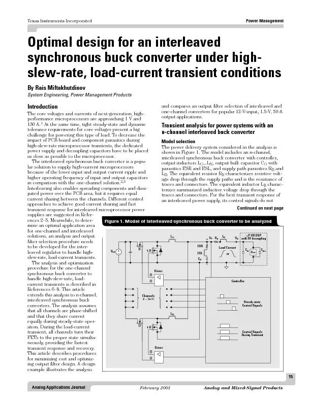
challenge for powering this type of load To decrease theas close as possible to the microprocessor
Presentation Embed Code
Download Presentation
Download Presentation The PPT/PDF document "15Analog Applications Journal" is the property of its rightful owner. Permission is granted to download and print the materials on this website for personal, non-commercial use only, and to display it on your personal computer provided you do not modify the materials and that you retain all copyright notices contained in the materials. By downloading content from our website, you accept the terms of this agreement.
15Analog Applications Journal: Transcript
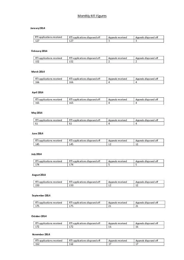
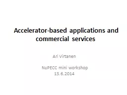
challenge for powering this type of load To decrease theas close as possible to the microprocessor. This article explores the topic more deeply by analyzing gain and noise The fully differential amplifier has multiple feedback paths and circuit analysis requires close attention to detail Care must be taken to include the OCM pin for a complete ana SIAK Journal Journal for Police Science and Practi Stolt Frank D 2012 Serial Arson Study of a phenomenon SIAK RXUQDO573475758157347RXUQDO57347IRU573473ROLFH573476FLHQFH57347DQG Practice SIAK Journal Journal for Police Science and Practi Brodbeck Silke 2012 Introduction to Bloodstain Pattern Analysis SIAK RXUQDO573475758157347RXUQDO57347IRU573473ROLFH573476FLHQFH57347DQG Pr Enhance Success in College . Eric Hotchkiss. Residence Director. SUNY Fredonia. Note from the Author. The . bulletin board with the . iPhone. in the center educates students about all . sorts of applications . January2014 RTI applications received RTI applications disposed off Appeals received Appeals disposed off 127 127 3 3 February2014 RTI applications received RTI applications disposed off Appeals recei Ari Virtanen. . NuPECC. mini workshop . 13.6.2014 . . Testing of space electronics. Microfilters. Radiopharmaceutical. . isotopes. 1. Main . commercial. . applications. 2. . Other. . applications. Catapult. ECIT. 12 September 2012. Paul Febvre. Satellite Applications Catapult Programme Director. Purpose - provide information about the . Satellite Applications Catapult. 2. Satellite technology. http://web.stanford.edu/class/cs142. Instructor: John Ousterhout. http://web.stanford.edu/~ouster. “OH-stir-. howt. ”. CS 142 Lecture Notes: HTML. Slide . 2. Introduction. There are several good reasons for taking . (. Confining the Wily Hacker. ). Ian Goldberg, David Wagner, Randi Thomas, and Eric Brewer. Computer Science Division. University of California, Berkeley. Presented . by:. Tahani . Albalawi. talbala1@kent.edu. PHMM Applications. 1. Mark Stamp. Applications. We consider 2 applications of PHMMs from information security. Masquerade detection. Malware detection. Both show some strengths of PHMMs. Both are somewhat unique . The CU-GLASSES. KH . W. ong. The design of a smart glass for VR applications V1.a. 1. Introduction. Be able to overlay images or text to our normal view. Simple, low cost and easy to build. Can duplicate for the 2. 1. Mark Stamp. K-Means for Malware Classification. Clustering Applications. 2. Chinmayee. . Annachhatre. Mark Stamp. Quest for the Holy . Grail. Holy Grail of malware research is to detect previously unseen malware. Volume 82 2003 article 111Book ReviewAlain JoxeEmpire of DisorderCambridge Mass MIT/Semiotexte 2002Reviewed by Michael WhealenAs a writing instructor at a large Canadian university with a reputation f College Ruled JournalPerfect for noting in college ruled journal for keep your note in one place with cactus design.College Ruled Journal details: - Cover: Tough matte paperback. - Dimensions: 8x 10 format for keep with you everywhere. - Perfect binding so pages will not fall out.- Managing all your note in one handy book.Hope you love this College Ruled Journal
Download Document
Here is the link to download the presentation.
"15Analog Applications Journal"The content belongs to its owner. You may download and print it for personal use, without modification, and keep all copyright notices. By downloading, you agree to these terms.
Related Documents
![[READ] - Notes: Cactus with Flower Journal, size 8 x 10 , Ruled Journal With Cute Journal](https://thumbs.docslides.com/905663/read-notes-cactus-with-flower-journal-size-8-x-10-ruled-journal-with-cute-journal-design-cute-college-journal.jpg)