/
521 CMR:   ARCHITECTURAL ACCESS BOARD    1/27/06 521 CMR - 111 521 CMR:   ARCHITECTURAL ACCESS BOARD    1/27/06 521 CMR - 111

521 CMR: ARCHITECTURAL ACCESS BOARD 1/27/06 521 CMR - 111 - PDF document

yoshiko-marsland
yoshiko-marsland . @yoshiko-marsland
Follow
437 views
Uploaded On 2017-11-22

521 CMR: ARCHITECTURAL ACCESS BOARD 1/27/06 521 CMR - 111 - PPT Presentation

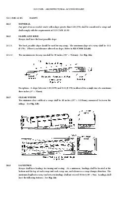
2400 RAMPS 245 HANDRAILS Handrails shall be provided at all ramps Handrails shall have the following features 2451 Location Handrails shall be provided along both sides of ramp segmen ID: 607560

24.00: RAMPS 24.5

Share:

Link:

Embed:

Download Presentation from below link

Download Pdf The PPT/PDF document "521 CMR: ARCHITECTURAL ACCESS BOARD ..." is the property of its rightful owner. Permission is granted to download and print the materials on this web site for personal, non-commercial use only, and to display it on your personal computer provided you do not modify the materials and that you retain all copyright notices contained in the materials. By downloading content from our website, you accept the terms of this agreement.


Presentation Transcript

521 CMR: ARCHITECTURAL ACCESS BOARD 521 CMR 24.00:RAMPS 24.1GENERAL Any part of an accessible route with a slope greater than 1:20 (5%) shall be considered a ramp and shall comply with the requirements of 521 CMR 24.00 24.2SLOPE AND RISE Ramps shall have the least possible slope. 24.2.1The least possible slope should be used for any ramp. The maximum slope of a ramp shall be 1:12 (8.3%). (There is no tolerance allowed on slope, Refer to 521 CMR 2.4.4d) 24.2.2The maximum rise for any run shall be 30 inches (30" = 762mm). See Fig. 24a. Exceptions: A slope between 1:10 (10%) and 1:12 (8.3%) is allowed for a single rise of a maximum three inches (3" = 76mm). 24.3CLEAR WIDTH The minimum clear width of a ramp shall be 48 inches (48" = 1219mm), measured between the railings. See Fig. 24b. 24.4LANDINGS amps shall have landings for turning and resting. At a minimum, landings shall be located at the bottom and the top of each ramp and each ramp run, and whenever a ramp changes direction. The maximum length of a ramp run between landings shall not exceed 30 feet (30' = 9m). Landings shall have the following features: Fig. 24c. 521 CMR: ARCHITECTURAL ACCESS BOARD 24.00: continued 24.4.1General: Landings shall be level and unobstructed by projections and door swings, except as permitted by 521 CMR 24.4.6. 24.4.2Width: The landing shall be at least as wide as the ramp run leading to it. 24.4.3Length: The landing length shall be a minimum of 60 inches (60" = 1524mm) clear. 24.4.5Dimensions for turning: If ramps change direction at landings, the minimum landing size shall be 60 inches by 60 inches (60" by 60" = 1524mm by 1524mm). See Fig. 24c. 24.4.6Doorways at Landings: If a doorway is located at a landing, then the level area in front of the doorway shall also comply with maneuvering clearances in Fig. 26d and 26e. 24.5HANDRAILS Handrails shall be provided at all ramps. Handrails shall have the following features: 24.5.1Location: Handrails shall be provided along both sides of ramp segments. 521 CMR: ARCHITECTURAL ACCESS BOARD 24.00: continued 24.5.2Heights: Handrails shall be provided in pairs, one at a height between 34 inches and 38 inches (34" - 38" = 864mm - 965mm), and a lower one at a height between 18 and 20 inches (18"- 20" = 457mm - 508mm), measured vertically from the surface of the ramp to top of handrail. 24.5.3Continuous surface: Handrails shall be continuous without interruption, except by doorways and openings, so that a hand can move from end to end without interruption. 24.5.4Extensions: Handrails shall extend at least 12 inches (12" = 305mm) beyond the top and bottom of the ramp and shall be parallel with the floor or ground surface ( Fig. 24d), except where the extension would cause a safety hazard. 24.5.5Size: Handrails shall have a circular cross section with an outside diameter of 1¼ inches (32mm) minimum and two inches (51mm) maximum. 24.5.6Shape: The handgrip portion of the handrail shall be round or oval in cross-section. See Fig. 24e. 24.5.7Surface: The gripping surface shall be free of any sharp or abrasive elements. 24.5.8Clearance: When a handrail is mounted adjacent to a wall, the clear space between the handrail and the wall shall be 1½ inches (1½" = 38mm). Handrails may be located in a wall recess if the recess is a maximum of three inches (3" = 76mm) deep and extends at least 18 inches (18" = 457mm) above the top of the rail. See Fig. 24e. 521 CMR: ARCHITECTURAL ACCESS BOARD 24.00: continued 24.5.9End condition: Ends of handrails shall be either rounded or returned smoothly to floor, wall, or post. 24.5.10Handrails shall not rotate within their fittings. 24.6CROSS SLOPE The cross slope of ramp surfaces shall be no greater than 1:50 (2%) 24.7SURFACES amp surfaces shall be stable, firm, and slip resistant. Ramps may be carpeted only if carpeting is installed in accordance with 521 CMR 29.3, Carpets. 24.8EDGE PROTECTION amps and landings with drop-offs shall have edge curbs, walls, railings, or projecting surfaces that prevent people from slipping off the ramp. Edge curbs shall be a minimum of two inches (2" = 51mm) high. 24.9OUTDOOR CONDITIONS Outdoor ramps and their approaches shall be designed so that water will not accumulate on walking surfaces. If gratings are used to disperse water, they shall comply with 521 CMR 22.00: WALKWAYS. 24.10CIRCULAR RAMPS Circular ramps are not permitted, except with the approval of this Board �� ��521 CMR: ARCHITECTURAL ACCESS BOARD 24.00: continued 24.5.9 End condition: Ends of handrails shall be either rounded or returned smoothly to floor, wall, or post. Handrails shall not rotate within their fittings. 24.6 CROSS SLOPE The cross sloperamp surfaces shall be no greater than 1:50 (2%) 24.7 SURFACES Ramp surfaces shall be stable, firm, and slip resistant. Ramps may be carpeted only if carpeting is installed in accordance with 521 CMR 29.3, Carpets24.8 EDGE PROTECTION Ramps and landings with drop-offs shall have edge curbs, walls, railings, or projecting surfaces that prevent people from slipping off the ramp. Edge curbs shall be a minimumoftwo inches(2"= 51mm) high. 24.9 OUTDOOR CONDITIONS Outdoor ramps and their approaches shallbe designed so that water will not accumulate on walking surfaces. If gratings are used to disperse water, they shall comply with 521 CMR 22.00: WALKWAYS24.10 CIRCULAR RAMPS Circular ramps are not permitted, except with the approval of this Board �� ��521 CMR: ARCHITECTURAL ACCESS BOARD 24.00: continued Heights: Handrails shall be provided in pairs, one at aheightbetween34 inchesand 38 inches (34" 38"= 864mm-965mm), and a lower one at a height between 18 and 20 inches (18"- 20" = 457mm - 508mm), measured vertically from the surface of the ramp to top of handrail. Continuous surface: Handrails shall be continuous without interruption, except by doorways and openings, so that a hand can move from end to end without interruption. Extensions: Handrails shall extend at least 12 inches (12" = 305mm) beyond the top and bottom of the ramp and shall be parallel with the floor or ground surface ( Fig. 24d), except where the extension would cause a safety hazard. Size: Handrails shall have a circular cross section with an outside diameter of 1¼ inches (32mm) minimum and two inches (51mm) maximum. Shape: The handgrip portion of the handrail shall be round or oval in cross-section. Fig. 24e24.5.7 Surface: The gripping surface shall be free of any sharp or abrasive elements24.5.8 Clearance:Whena handrail is mounted adjacent to a wall, the clear space between the handrailand the wall shall be 1½ inches (1½" = 38mm). Handrails may be located in a wallrecess if the recess is a maximum of three inches (3" = 76mm) deep and extends at least 18 inches (18" = 457mm) above the top of the rail. Fig. 24e �� ��521 CMR: ARCHITECTURAL ACCESS BOARD 24.00: continued 24.4.1 General: Landings shall be level and unobstructed by projections and door swings, except as permitted by 521 CMR 24.4.624.4.2 Width: The landing shall be at least as wide as the ramp run leading to it. 24.4.3 Length: The landing length shall be a minimum of 60 inches (60" = 1524mm) clear24.4.5 Dimensions for turning: If ramps change direction at landings, the minimum landing size shall be 60 inches by 60 inches (60" by 60" = 1524mm by 1524mm). Fig. 24c24.4.6 Doorways at Landings: If a doorway is located at a landing, then the level area in front of the doorway shall also comply with maneuvering clearances in Fig. 26d and 26e24.5 HANDRAILS Handrails shall be provided at all ramps. Handrails shall have the following features: Location: Handrails shall be provided along both sides of ramp segments. �� ��521 CMR: ARCHITECTURAL ACCESS BOARD 521 CMR 24.00: RAMPS 24.1 GENERAL Any part of an accessible route with a slope greater than 1:20 (5%) shall be considered a ramp and shall comply with the requirements of 521 CMR 24.00 24.2 SLOPE AND RISE Ramps shall have the least possible slope. 24.2.1 The least possible slope should be used for any ramp. The maximum slope of a ramp shall be 1:12 (8.3%). (There is no tolerance allowed on slope, Refer to 521 CMR 2.4.4dThe maximum rise for any run shall be 30 inches (30" = 762mm). Fig. 24a Exceptions: A slope between 1:10 (10%) and 1:12 (8.3%) is allowed for a single rise of a maximum three inches (3" = 76mm). 24.3 CLEAR WIDTH The minimum clear width of a ramp shall be 48 inches (48" = 1219mm), measured between the railings. Fig. 24b 24.4 LANDINGS Ramps shall have landings for turning and resting. At a minimum, landings shall be located at the bottom and the top of each ramp and each ramp run, and whenever a ramp changes direction. The maximum length of a ramp run between landings shall not exceed 30 feet (30' = 9m). Landings shall have the following features: Fig. 24c