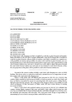
/
cycle) is shown on Fig. 4. At this moment blades 1 rotate about axes 2 cycle) is shown on Fig. 4. At this moment blades 1 rotate about axes 2

cycle) is shown on Fig. 4. At this moment blades 1 rotate about axes 2 - PDF document

yoshiko-marsland
yoshiko-marsland . @yoshiko-marsland
Follow
423 views
Uploaded On 2015-09-09

cycle) is shown on Fig. 4. At this moment blades 1 rotate about axes 2 - PPT Presentation

The purpose of this work is development of wind wheel design which blades can perform additional movements in the direction of the projection action of lift force perpendicular on wind wheel blade rot ID: 125394

The purpose this work

Share:

Link:

Embed:

Download Presentation from below link

Download Pdf The PPT/PDF document "cycle) is shown on Fig. 4. At this momen..." is the property of its rightful owner. Permission is granted to download and print the materials on this web site for personal, non-commercial use only, and to display it on your personal computer provided you do not modify the materials and that you retain all copyright notices contained in the materials. By downloading content from our website, you accept the terms of this agreement.


Presentation Transcript

cycle) is shown on Fig. 4. At this moment blades 1 rotate about axes 2 with angle rate counterclockwise, and wind wheel element 3 under action of wind-driven plant elements in which it is installed, begins rotating with angle rate 2 about axes 4 counterclockwise, at that, axes 2 being rotation center of blades 1 and rotating about axis 4 move rotating center through an arc about axis 4, as well as rotate about axes 2 with advanced angular rate (2 – ), at that, each blade 1 occupies such position as regard to axis 2 that corresponds to Fig. 1. After rotation of blades through 45º from its original position and wind wheel element through 90º, wind wheel will occupy position shown on Fig. 5. At further rotation of blades through 90º (from the original position on Fig. 4) and wind wheel through 180º angle, wind wheel will occupy position shown on Fig. 6, and in this position angle (Fig. 1 and Fig. 2) will be 90º. At further rotation of blades to position 135º, and wind wheel element – to 270º, wind wheel will be in position corresponding to Fig. 7. After rotation of blades to position 180º and wind wheel element – to 360º (Fig. 8), each blade 1 will occupy such position as regard to its axis that corresponds to Fig. 2. At that, the process of blades rotation about axis 4 in plane perpendicular to rotation plane finishes. Hereafter wind wheel element 3 stops, and blades 1 begin rotating about their axes 2 counterclockwise. In position shown on Fig. 9 they rotate through 90º and as regard to axes angle (Fig. 1 and Fig. 2) will be 90º. At further rotation of blades up to 180º wind wheel will occupy position corresponding to Fig. 4, and blades 1 as regard to their axes 2 will be in position corresponding to Fig. 1, and wind wheel will occupy the original position for performing of the next cycle. The purpose of this work is development of wind wheel design which blades can perform additional movements in the direction of the projection action of lift force perpendicular on wind wheel blade rotation plane performing at that additional operation that hereinafter can be conversed by wind-driven plant to additional power on generator axis and returned to the original position without additional energy consumption. The purpose in view is achieved in such a way that each blade is installed on each axis with possibility of rotation. Axes are fixed motionlessly in wind wheel element, located under certain angle to wind wheel rotation plane and at equal space to its rotation axis. The process of blade performance of additional movements is shown on the example of individual blade 1 and axis 2 (Fig. 1, 2) provided motionless blade 1. At the beginning there is angle between blade 1 plane and axis 2, at rotational motion of axis 2 through 180º the angle increases, because blade 1 rotates performing additional movement and provided a force is applied to it, performing additional operation that hereafter can be conversed by wind-driven plant to additional power. Since for arising of lift force in blade it must rotate, then for performance of additional movements during blade 1 rotation through 180º - axis 2 must rotate through 360º, the original and final position of this process (operating cycle) is given on Fig. 1 and 3. For coming of blade 1 to the original position, Fig. 1, axis 2 does not rotate, and blade 1 performs rotation about it through 180º, the original and final position of this process (null cycle) is shown on fig. 3 and 1. At that, axis 2 is motionless and blade rotates in motionless plane, because this plane is under angle to rotation axis of axis 2, blade has the possibility without additional movements as regard to its rotation axis to come to the original position (Fig. 1) for beginning of operating cycle. For wind-driven plant operation, as a rule, it is necessary to have several blades 1 (Fig. 1), for that, they are installed with possibility of rotation on axes 2 that are fixed motionlessly to wind wheel element 3, that is installed with possibility of rotation in wind-driven plant. At that, axes 2 have the possibility to rotate about rotation axis 4 of wind wheel element 3. Fig. 1 shows blade installed on axis, side-view; Fig. 2 shows blade position after axis rotation through 180º, side-view; Fig. 3 shows blade position after its rotation through 180º and axis rotation through 360º, side-view; Fig. 4 shows two-blade wind wheel with offset axes, front view; Fig. 5 shows two-blade wind wheel after rotation of blades through 45º and wind wheel element through 90º, front view; Fig. 6 shows two-blade wind wheel after rotation of blades through 90º and wind wheel element through 180º, front view; Fig. 7 shows two-blade wind wheel after rotation of blades through 135º and wind wheel element through 270º, front view; Fig. 8 shows two-blade wind wheel after rotation of blades through 180º and wind wheel element through 360º, front view; Fig. 9 shows two-blade wind wheel after rotation of blades through 270º at motionless wind wheel element, front view. Wind wheel with changing blades, Fig. 4, contains blades 1 installed with the possibility of rotation on axes 2 that are fixed motionlessly in wind wheel element 3 that is installed in elements of wind-driven plant with possibility of rotation about axis 4. Axes 2 are manufactured in form of two journals located at an angle to each other, fig. 1, blade is fixed on one journal, the other is fixed at equal space and symmetrically to rotation axis of wind wheel 3 (Fig,. 4), blades 1 are installed with the possibility of contact with wind-driven plant elements providing lifting capacity at rotation of blades. Axes 2 are oriented in such a way that they form acute angle with reference plane formed by axis 4 and central fixing point of axis 2 to element 3 (on Fig. 1 this angle is 90-), axis 2 projection on this plane will be parallel to axis 4. At the plant operation wind wheel blades 1 with changing axes take wind pressure and begin rotating about their axes 2. The original position in which blades under action of lifting forces begin performing movement in plane perpendicular to plane of their rotation (operating UKRAINE (19) UA (11) 86068 (13) C2MINISTRY OF EDUCATION (51) (2009) AND SCIENCE OF UKRAINE F03D 7/00 STATE DEPARTMENT OF INTELLECTUAL PROPERTY DESCRIPTION TO INVENTION PATENT ____________________________________________________________________________ (54) WIND WHEEL WITH CHANGING AXES _____________________________________________________________________________ (21) a200614065 (22) 29.12.2006 (24) 25.03.2009 (46) 25.03.2009, Bul # 6, 2009 (72) Poshukaylo Valeriy Mykhaylovych, UA (73) Poshukaylo Valeriy Mykhaylovych, UA (56) UA 53329, 15.01.2003 UA 62396, 15.12.2003 SU 98693, 05.09.1949 US 1742123, 21.02.1929 US 1982039, 23.01.1933 GB 735111, 24.04.1952 DE 3319165, 06.12.1964 (57) Wind wheel with changing axes that is installed in wind-driven plant elements and includes blades that differs in the fact that it contains additionally wind wheel element that is installed in wind-driven plant elements with possibility of rotation, each blade is installed on a separate axis with possibility of rotation and possibility of contact with wind-driven plant elements, axes are fixed motionlessly in wind wheel element and located at equal spaces and symmetrically to wind wheel element rotation axis, each axis is located at an acute angle to plane that passes through the wind wheel element rotation axis and center of axis fixation to wind wheel element, at that, the axis projection on this plane will be parallel to wind wheel element rotation axis. __________________________ Pursuant to the current wording of MKB, wind wheel with changing axes refers to F03D heading. This device refers to wind power field and is intended for use in composition of wind-driven plant with wind wheel with changing axes. There is wind wheel with self-aligned space pursuant to (19) US, (11) 1742123, that contains blades installed in hub having possibility of axial movement on wind wheel shaft, and force on blade is transmitted by means of connecting link with circular groove, sliding blocks, ball-and-socket bearings and pins. The weak point of this design is absence of possibility of wind wheel mechanisms to take movement of blades under lift force action arising at rotating movement of blades. There is wind wheel with regulated rotation rate pursuant to (19) US, (11) 1460400, that contains rotating blades equipped with crane and hollow shaft within which torsion bar with cross bar are installed that is connected kinematically with blades through levers fixed on cross bar and blade and contacting with each other. The weak point of this design is impossibility of transmitting by levers of forces arising in blades under lift force action.