/
Status  of AH1  and  options  for 3.9GHz R&D   Cecilia Maiano Status  of AH1  and  options  for 3.9GHz R&D   Cecilia Maiano

Status of AH1 and options for 3.9GHz R&D Cecilia Maiano - PowerPoint Presentation

yoshiko-marsland
yoshiko-marsland . @yoshiko-marsland
Follow
344 views
Uploaded On 2019-11-01

Status of AH1 and options for 3.9GHz R&D Cecilia Maiano - PPT Presentation

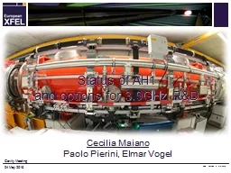
Status of AH1 and options for 39GHz RampD Cecilia Maiano Paolo Pierini Elmar Vogel Cavity Meeting PPT version 0 352016 04 May 2016 Outline Performance of AH1 in Injector Spare module preparation ID: 762075

maiano cavity meeting04 2016 cavity maiano 2016 meeting04 power meeting ah1 beam installation module coupler phase spare cavities distribution

Share:

Link:

Embed:

Download Presentation from below link

Download Presentation The PPT/PDF document "Status of AH1 and options for 3.9GHz..." is the property of its rightful owner. Permission is granted to download and print the materials on this web site for personal, non-commercial use only, and to display it on your personal computer provided you do not modify the materials and that you retain all copyright notices contained in the materials. By downloading content from our website, you accept the terms of this agreement.


Presentation Transcript

Status of AH1 and options for 3.9GHz R&D Cecilia MaianoPaolo Pierini, Elmar Vogel Cavity Meeting PPT version 0 3/5/2016 04 May 2016

OutlinePerformance of AH1 in Injector Spare module preparationOpportunities for CW R&D at 3.9 GHz 04/May/2016 C.Maiano, Cavity Meeting2

SUMMARY OF AH1 Perfomance IN INJECTOR3 C.Maiano, Cavity Meeting04/May/2016

Cavity vertical tests at INFN/LASAC.Maiano, Cavity Meeting 04/May/2016 AH1 cavities: First vertical test 26-Sep-14 and last 11-Feb-2015 4PERFORMANCE GOAL (SPEC): 15*0.346*8 ~ 42 MVBeam Dynamic Requirements (worst case scenario ) < 30 MV

Major AH1 Assembly MilestonesC.Maiano, Cavity Meeting 04/May/2016 September 23 2015 July 3 20155

The assembly in Halle III (14 weeks)C.Maiano, Cavity Meeting 04/May/2016 6

Module assembly timelineP. Pierini, 14th XFEL MAC Meeting 02/May/2016Where WhenActivity14 weeks from cavities to tunnelCLEAN ROOM (3 wks)WK25Clean room preparation, last coupler installed on cavitiesWK26String installation start. Cavity connectionsWK27Finish installation. String Roll-outROLL-OUT AREA ON GIRDER(2 wks)WK28Partial magnetic shield installation and tuner installation, T sensorsWK292 phase line welds, T sensor installation completion, tuner motor ROLL-OUT AREA SUSPENDED(2 wks)WK30Suspension from cold mass, completion of magnetic shield, alignmentWK31End of string alignment (2 pass and final survey), transfer to cantilever, preparation of 2K thermal sinking (HOM, motor), HOM notch filter tuningCANTILEVER(4 wks)WK32Weld of the magnet package current leads, weld of the warmup circuitWK33RF cables, completion mag shield, HOM thermal sinks, installation of coupler cones, cable thermalization, start assembly of 4K shield parts WK34 Finalization of 4K/80K shields and MLI blankets WK35 Vessel roll-on , post bracket/suspension of the Cold Mass on the Vacuum Vessel, longitudinal pre-alignment of CM to VV, transfer to floor supports FLOOR SUPPORT (3 wks ) WK36 CM to VV alignment, start of coupler installation WK37 Finish coupler installation on one side, install coupler vacuum pump line WK38 Coupler side two, coupler vacuum, beam vacuum & leak check WK39 Transport to Tunnel

Final Preparation stages in tunnelAssembly WG distributionInjector String IntegrationDec 10: Start cooldown Dec 15, cavity pre-tuning Dec 16, calibration: AH1 ReadyC.Maiano, Cavity Meeting04/May/2016 November 11 20158

RF Commissioning in TunnelInfrastructure aspects, workload of AMTF and schedule delays (arrival of 3.9 components) made it impossible to test the module before tunnel installationTunnel installation without cryogenic and RF testing Tunnel is not the most favorable environment for precise RF measurements activitiesFew RF power meters with respect to AMTF, though a few not initially foreseen were implemented by MHF-sl (e.g. HOM power readings, not present in the main linac)The positive aspect is that all subcomponents were in their final configuration and driven by the XFEL control systemSmooth transition from characterization to operationC.Maiano, Cavity Meeting04/May/20169

Klystron operated by LLRF on load10 C.Maiano, Cavity Meeting04/May/2016 Operation on load, achieved 61 kW power at saturation

Present RF Distribution layout11 C.Maiano, Cavity Meeting04/May/2016 Output of LLRF VMPreAmpKLYPMeter (Cal)Only to LLRF Cavity 1Cavity 3Cavity 5Cavity 7Cavity 2 Cavity 4 Cavity 6 Cavity 8 Check of the WG distribution flatness performed only at few W level after assembly Courtesy of R. Jonas, MIN

Cavity Phasing and QL adjustmentWG distribution uses 3dB splitters to provide RF power to cavities from a single KlystronNo phase shifters Flexible waveguide sectionsAssembled in tunnelno measurements at relevant Kly power Fixed coupler designThe systems relies on 3-stub tuners to achieve the desired QL adjustment and cavity phasing 12C.Maiano, Cavity Meeting 04/May/2016Directional Coupler3-stub tuner

Main characterization checklistCavity performances, up to quench limit - donePhase alignment and QL tuning - done Beam-based calibrations - doneHOM thermal stability studies - doneCryogenic performance assessment - done Preserving (and improving) beam quality – ongoingCharacterization of the RF power distribution – skipped (for schedule reason) C.Maiano, Cavity Meeting04/May/201613

First operation at nominal gradient on Day 118 December 2015Operation with no beam First rough calibration (LLRF)Assume Pcav=Pkly/10 Nominal pulse structure Fill: 750 us/FlatTop: 650 usGradient well above nominal40 MV of VS voltageFirst quench > 45 MV Cavity phasing missing and QL values not yet tunedLLRF in FB modeC.Maiano, Cavity Meeting04/May/2016Arbitrary calibration/need beam14

Initial QL values (nominal 3.2E6)Cumulative effect of antenna / cavity tolerancesSpread in the QL values (all stubs out), factor of 2 15C.Maiano, Cavity Meeting04/May/2016 TUNING

Beam Based calibration: Cavity PhasesJanuary 2016, on beamBeam transientsPhase CalibrationsPreliminary to : Phase TuningQL tuningLarge initial cavity phase spread WG assembled in tunnel, no cal.C.Maiano, Cavity Meeting 04/May/2016 Beam induced cavity gradient changesCavity transient, QL determination and phase calibration Tune with3-stub tunersWG Spacers160°After operation of a few stub tuners16

QL tuning & Phase alignment1 February 2016, AH1 moved 1 ms after the beamAllow injector commissioning while aligning cavity phasesIndividual maps of all 3-stub tuner positions C.Maiano, Cavity Meeting04/May/2016 QL-Phase region Case of design in range of tunerQL-Phase regionCase of design outside range of tunerWG spacers installed on 3 cavities17

Started regular operation in injector10 February 2016QL aligned well within the 10% requirementPhases within 15° 16 February 2016 Back on beamMoved to -180°(wrt on-crest), calibration with beam energyC.Maiano, Cavity Meeting 04/May/2016 18

Max QL obtainable in present moduleBy mapping all tuners we were able to reach high QL values with the present antenna designEasy without phase constraints (single 1:1 powering) 19C.Maiano, Cavity Meeting04/May/2016 Cav 123 45678Max QL~ 1E7~ 4E7~ 3E7~ 3E7~ 4E7~ 1E7~ 3E7~ 4E7 Already close to values for CW operation

Quench Gradients in tunnelC.Maiano, Cavity Meeting 04/May/2016 Cav TunnelVT Max GradientLimitGradient C1 18.1 MV/m Quench 21.0 MV/m C2 17.6 MV/m Power 20.0 MV/m C3 18.7 MV/m Quench 20.8 MV/m C4 17.1 Mv /m Power 22.0 MV/m C5 18.2 Mv/m Quench 21.0 MV/m C6 17.6 Mv/m Power 19.6 MV/m C7 17.7 Mv/m Quench 20.0 MV/m C8 17.3 Mv/m Power 21.8 MV/m Tunnel measurement much less accurate WG distribution assumed uniform (3x3dB+loss) 20 Error on the individual cavity gradient estimation not yet analyzed but probably as large as 30%

After final round of Beam Based CalibrationC.Maiano, Cavity Meeting 04/May/2016 After LLRF final calibration with beam induced transients an asymmetry of the WG distribution is apparent (left/right arms of the distribution system Confirmation requires dedicated measurements of WG distribution at high power (@Cav Directional Couplers) Regular closed loop operation, at 20 MV setpointEven-numberedOdd-numberedRequires RF cables disconnection to LLRF panel & several accessess with measurement equipmentDid not proceed as module performances are reached with margins! 21

Detuned HOMsThe installation of the power coupler detunes the notch filter in front of it Perturbation of the field pattern locally in the small structures at 3.9 GHzA retuning was needed Cavity 1 was suboptimally tunedCould have done better, but did not yet have the operational experience to set better requirements during tuning (now we would not miss it)Cavity 4 was already at its limitLarge deformation of the can, to a point where capacity no longer changes and risk of cavity integrity was high! 22C.Maiano, Cavity Meeting04/May/2016

HOM performanceC.Maiano, Cavity Meeting 04/May/2016 Cav QH1 QH2C17.29E+095.64E+11 C2 1.14E+12 5.72E+10 C3 8.70E+10 1.33E+11 C4 1.91E+09 6.29E+11 C5 3.18E+11 2.68E+11 C6 8.32E+11 5.05E+11 C7 1.36E+11 6.28E+10 C8 4.50E+11 1.19E+15 Cavity Q0 is 2E9 (VT measure) Qt is 1E10 (VT calib) C1 HOM1 suboptimal tuning C4 HOM1 detuned (cavity Q0) However, stable thermal behavior at 10 Hz operation up to SP in excess of 40 MV What about CW? 23

Temperature stability at highest SPC.Maiano, Cavity Meeting 04/May/2016In spite of the large peak fundamental mode power leaking out of two HOM1 couplers temperatures are extremely stable 10 Hz! 1% d.c.Three CERNOX sensors are at each HOM can end (flange, top-hat and inner antenna base) and connected to technical interlock systemNever triggered! 40 MVLevels at 20 MV24 Power C1H1 C4H1Temperature increaseV SP

Cryogenic aspects (only static so far)Static loads of individual component in the injector circuit cannot be individually assessed, only global measurements can be doneIncluding end and feed box and both modulesHowever, using data from components assessed in AMTF MKS estimates 2 K: 4-7 W5/8 K: N/A problems with flowmeters40/80 K: approx 95 WOverall, performance similar to 1.3 GHz modules Somewhat expected, same concept, same # penetrationsWell within capabilities of cryocapabilities at injector C.Maiano, Cavity Meeting04/May/201625

First confirmation of linearization effectTDS diagnostic not yet available at injector12 April 2015 transmission of full train with acceptable losses in the beamline after last dipole to dump not possible without AH1 to get rid of the energy tails with A1 on-crest C.Maiano, Cavity Meeting04/May/2016 AH1=0 MV AH1=10 MV26

Spare MODULE27 C.Maiano, Cavity Meeting04/May/2016

Now: All 20 cavities are tested (AH1 + spare)C.Maiano, Cavity Meeting 04/May/2016 28

Spares components5 cavities for spare module presently at DESY2 from previous series production3 from the second series of 10 cavities 5 more cavities tested, expected before end May/mid JuneLast 2 cavities of the second series delayedVessel integration non-conformities: RepairModule (CM and VV) at DESYSeveral other components already have been procured in quantities for 2 modules and are already in stock either at DESY, INFN or FNALCouplers, magnet, magnetic shields, PU and HOMs, beam line flange transitions, vacuum line, waveguides, etc. C.Maiano, Cavity Meeting04/May/2016 29

Spare module activitiesString assembly and module installation scheduled to start in September, after tunnel closure and DESY Clean Room maintenance Increased manpower availability for all operations with the end of tunnel assembliesAdaptation of the module support rail for XATB1 in AMTF ongoing (BINP procurement)Ready before end of 2016Testing in nominal XFEL pulsed conditions in early 2017XATB1 already equipped with RF (used for single cavity tests)Can the test scope be extended to CW (similar to 1.3)? C.Maiano, Cavity Meeting04/May/2016 30

CW testing of X3M2 in AMTFModule will be here/needed as spare part of XFEL injectorXATB1 will host the pulsed tests, which are scheduled and funded by the spare part agreementsCW RF is missing, but all other ingredients are there and possible high duty cycle upgrades to XFEL will require to assess the feasibility of a 3.9 GHz CW system Started inquiring options for RF systemTwo companies exploring 3.9 GHz SSA @ 1 kW1 proposal: 10 k€ feasibility + 1 kW units @ 70-80 k€ 1 other still in conceptual phaseCurrently no budget, just the opportunity to discuss the idea! C.Maiano, Cavity Meeting04/May/2016 31

SummaryRF commissioning of the 3.9 GHz module in the tunnel was a great successAchieved performances above nominal during the early injector commissioning stages in December 2015, with the AH1 pulse shifted in time from the beam Module in regular operation with beam since January 2016Final verification will be achieved with TDSThe second spare module is well proceeding towards assembly & testingAn extended test scope for CW testing with SSA can be conceived, in view of the possible future high duty cycle upgrades of the XFEL facility C.Maiano, Cavity Meeting04/May/2016 32

Thanks! WP46: 3.9 GHz System C.Maiano, Cavity Meeting04/May/2016AcknowledgementsINFNM.Bertucci, M. Bonezzi, A.Bosotti, JF.Chen, M.Chiodini, M.Fusetti, P.Michelato, L.Monaco, M.Moretti, C.Pagani, R.Paparella, D. Sertore DESYToo many people from MIN, MKS 1, MKS 3, MHF-SL, MPL, MSK, etc. And especially the whole BKR teamFNALElvin Harms and the ACC39 team Most photos courtesy of D. Nölle/Ettore Zanon S.p.A.33