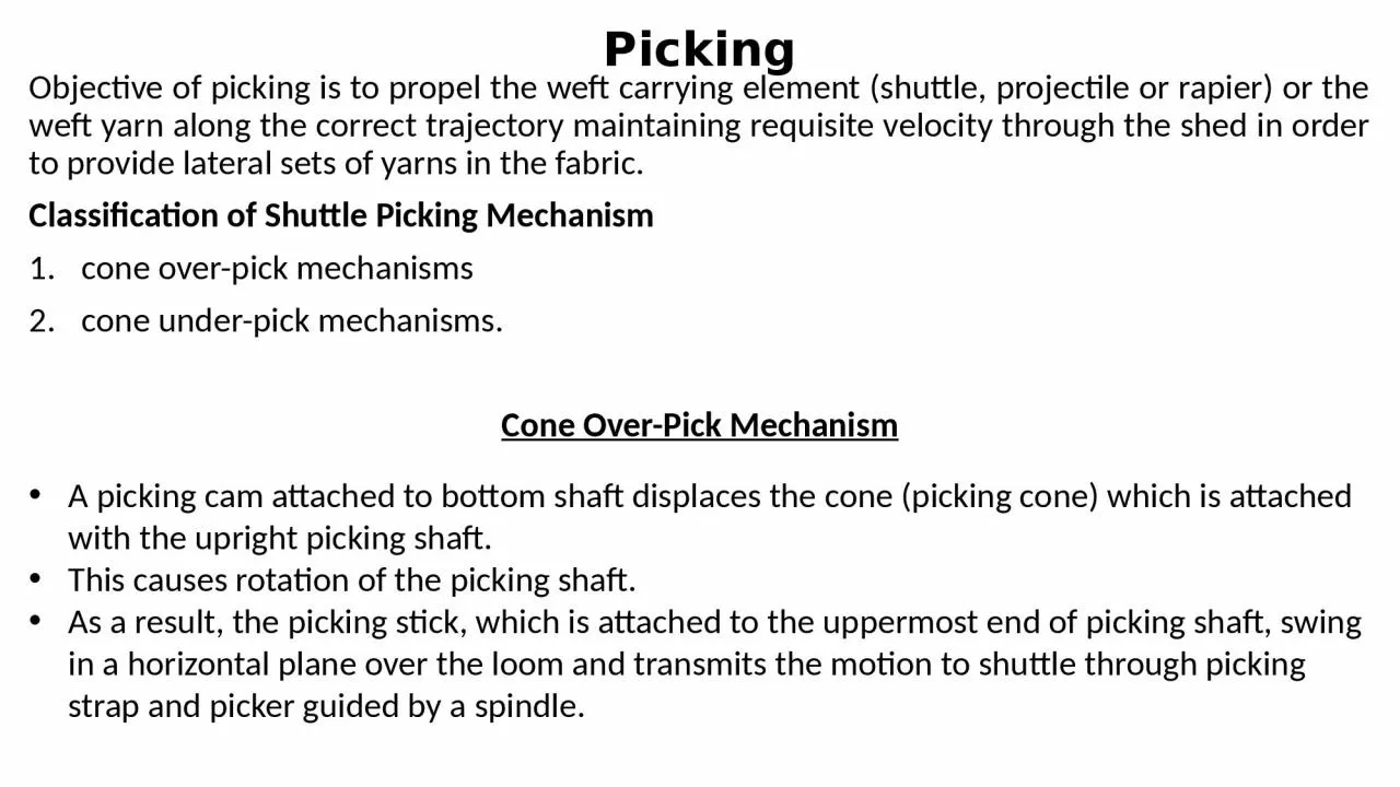
/
Picking Objective of picking is to propel the weft carrying element (shuttle, projectile Picking Objective of picking is to propel the weft carrying element (shuttle, projectile

Picking Objective of picking is to propel the weft carrying element (shuttle, projectile - PowerPoint Presentation

BlueberryBelle
BlueberryBelle . @BlueberryBelle
Follow
342 views
Uploaded On 2022-07-28

Picking Objective of picking is to propel the weft carrying element (shuttle, projectile - PPT Presentation

Classification of Shuttle Picking Mechanism cone overpick mechanisms cone underpick mechanisms Cone OverPick Mechanism A picking cam attached to bottom shaft displaces the cone picking cone which is attached with the upright picking shaft ID: 930835

shuttle picking shaft loom picking shuttle loom shaft pick speed sley stick picker cone strap timing crank increase system

Share:

Link:

Embed:

Download Presentation from below link

Download Presentation The PPT/PDF document "Picking Objective of picking is to prope..." is the property of its rightful owner. Permission is granted to download and print the materials on this web site for personal, non-commercial use only, and to display it on your personal computer provided you do not modify the materials and that you retain all copyright notices contained in the materials. By downloading content from our website, you accept the terms of this agreement.


Presentation Transcript

Slide1

Picking

Objective of picking is to propel the weft carrying element (shuttle, projectile or rapier) or the weft yarn along the correct trajectory maintaining requisite velocity through the shed in order to provide lateral sets of yarns in the fabric. Classification of Shuttle Picking Mechanismcone over-pick mechanismscone under-pick mechanisms. Cone Over-Pick Mechanism

A picking cam attached to bottom shaft displaces the cone (picking cone) which is attached with the upright picking shaft.

This causes rotation of the picking shaft

.

As a result, the picking stick, which is attached to the uppermost end of picking shaft, swing in a horizontal plane over the loom and transmits the motion to shuttle through picking strap and picker guided by a spindle

.

Slide2

Here picker is constrained by the spindle to move in a straight line which otherwise would have followed a path of arc.

Moreover, pairs of picking cam and follower installed at either end of the loom have seldom ensured picking of equal strength (force).Frequent adjustment of picking-strap or picking cam and nose settings is required.Possible Adjustments for Strength and Timing of Over-PickShortening picking-strap increases the shuttle speed, but timing of picking advances.The picking tappet can be turned over bottom shaft for the adjustment of picking timing.Lowering the picking cone in the slot increases the shuttle speed but timing of picking is

delayed.

Angular adjustment between picking shaft and picking stick also changes shuttle speed and timing (unpredictable).Large change in shuttle speed for wider loom can be achieved by changing either nose bit or the entire picking cam.

Slide3

Cone Under-Pick Mechanism

a picking cam attached to bottom shaft displaces the cone turning the picking shaft (side shaft) located horizontally. The other end of the picking shaft is connected with upright picking stick through the picking strap (lug strap).This causes the picking stick to move in a vertical plane and transmits the motion to shuttle by the picker attached at the upper end of it.

Slide4

In this system the picking stick and other appendages are located below the shuttle trajectory while picking cams and follower, as usual, below the loom and driven from bottom shaft.

The system is naturally suitable for automatic looms. Here picker slides over its spindle and picking timing is regulated by cam adjustment like in over pick motion. An almost inextensible lug strap allows shuttle speed adjustment by either raising or lowering it around picking stick. Absence of stretchable parts in under-pick system ensures the retention of correct setting over long period in contrast with the cone over-pick mechanism.Possible Adjustments for Strength and Timing of under-PickTiming of picking is changed by turning the cam on the bottom shaft.

Raising and lowering of the lug strap (picking strap) reduces and increases shuttle velocity respectively.

Two independent adjustments for velocity and timing of shuttle make the under-pick system less complicated.

Slide5

Parallel Pick Mechanism: cone

underpickIn a modified under-pick system, picker guiding spindle is eliminated and picker itself is kept attached to the stick.The lower end of the stick is made to oscillate over a curvilinear shoe which rests upon a plate. The shoe and picker trajectory form the circumference of a semi-circle.This ensures picker movement in a perfect straight line and hence that of the shuttle which is a prime requirement for high speed looms.Picking stick in its extension passes through the slot of a plate and connected with loom frame through a spring for proper return.

Slide6

Link Pick Mechanism: cone

underpickAttempt to increase loom speed further creates one unfavorable situation where contact between shoe and plate is often disrupted resulting undesirable picker movement which deflects shuttle from its right path or undue wear of it and even fly-out. Modification through link pick is done to overcome this limitation. Here a metal piece (M) attached to the lower end of the picking stick. M connects itself to a bracket (B) fastened to the sley

sword through two arms (A).

Such four bar linkages are, as if, an irregular quadrilateral whose shape and sizes in relation to the length and angular movement of the picking stick, if properly designed can deliver very good result in terms of accuracy over a distance of 15-20 cm along shuttle path and truly exercises positive control in the system even at very high speed.

Slide7

Shuttle Velocity and Loom Speed

Let us assume the following notations:P = Loom speed (picks/min.) or number of revolution of crank shaft/min.R = Width of the reed (m)v = Average shuttle velocity (m/s)L = Effective length of shuttle (m)θ  = Degree of crank shaft rotation available for the passage of the shuttle through the shed.

t

 = time required for the shuttle passage through the shed (s)Now the distance covered by the shuttle in t sec = (R+L

) m

Slide8

Slide9

It can be noted that from Equation 4 that for a given loom width and shuttle length, if we desire to increase the loom speed, we must increase either v or θ or both.

an increase in  θ  can be achieved by increasing the sley eccentricity (e) as sley remains towards the back centre of the loom for a longer duration if sley eccentricity is more. Thus the shuttle can avail greater duration for its flight through the shed. A high value of sley eccentricity should be avoided to reduce wear and tear of the loom.

In addition, an increase in 

θ  causes problem for fast reed warp protector motion, because in order to prevent the shuttle trapping, the shuttle should strike the swell in proper time. It, therefore, restricts the increase of 

θ.

On

the other hand, an increase in 

v

 requires more kinetic energy to be dissipated during shuttle checking which increase wear of the loom frame. From this above argument, it is clear that the loom speed is limited in the shuttle loom.

Slide10

The product of P

and (R+L) is known as the Weft Insertion Rate (WIR), which is a measure of loom productivity. Unit of WIR is m/min.From Equation 4, for a given v and θ, we have:However, this theoretical relationship largely deviates from the actual practices.A good approximation of the relationship between the loom speed and loom width can be expressed by using the inverse-square-root rule, i.e.

Slide11

Power Required for Picking

The energy used to accelerate the shuttle is equal to its kinetic energy when it leaves the picker.

Slide12

Picking

The objective of the shuttle checking is to retard the shuttle nullifying its kinetic energy to zero.MechanismThe incoming shuttle gets rubbed on the spring loaded swell and thereby the frictional force slows down the shuttle velocity. The velocity of the incoming shuttle is reduced around 30% by the action of swell. The shuttle is finally stopped as it collides with the picker, which is cushioned by a suitable buffer system.

Slide13

Beat up

To push the newly inserted pick up to the cloth fellTo ensure uniform pick spacing in the fabricSley MotionBeat-up is done by the reed which is carried by the sley. Sley derives its rectilinear reciprocating motion from the rotating crank shaft through the connections of crank and crank arm which makes a four-bar linkage mechanism.

Radius of the crank = OA= r, lengthy of the crank arm= AB =l

Slide14

Sley Eccentricity

As sley motion deviates from SHM, during its backward journey, sley covers more displacement from rotation of crank shaft than the rotation of crankshaft. Similarly during its forward journey, sley covers less displacement from rotation of crankshaft than the rotation of crankshaft.

This

difference in the sley displacement during its backward and forward movement is termed as sley eccentricity