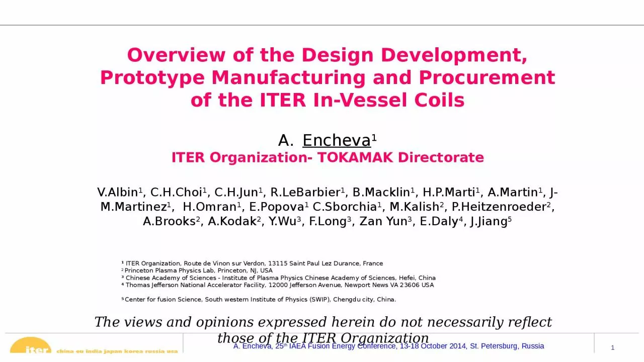
Organization Overview of the Design Development Prototype Manufacturing and Procurement of the ITER InVessel Coils Encheva 1 ITER Organization TOKAMAK Directorate VAlbin 1 CHChoi 1 ID: 934877
Download Presentation The PPT/PDF document "The views and opinions expressed herein ..." is the property of its rightful owner. Permission is granted to download and print the materials on this web site for personal, non-commercial use only, and to display it on your personal computer provided you do not modify the materials and that you retain all copyright notices contained in the materials. By downloading content from our website, you accept the terms of this agreement.
Slide1
The views and opinions expressed herein do not necessarily reflect those of the ITER Organization
Overview of the Design Development, Prototype Manufacturing and Procurement of the ITER In-Vessel Coils Encheva1ITER Organization- TOKAMAK DirectorateV.Albin1, C.H.Choi1, C.H.Jun1, R.LeBarbier1, B.Macklin1, H.P.Marti1, A.Martin1, J-M.Martinez1, H.Omran1, E.Popova1 C.Sborchia1, M.Kalish2, P.Heitzenroeder2, A.Brooks2, A.Kodak2, Y.Wu3, F.Long3, Zan Yun3, E.Daly4, J.Jiang5
1
ITER
Organization
, Route de
Vinon
sur Verdon, 13115 Saint Paul Lez Durance, France
2
Princeton
Plasma Physics Lab, Princeton, NJ, USA
3
Chinese Academy of Sciences -
Institute of Plasma Physics Chinese Academy of Sciences
, Hefei, China
4
Thomas Jefferson National Accelerator Facility, 12000 Jefferson Avenue, Newport News VA 23606 USA
5
Center
for fusion Science,
South western
Institute of Physics (SWIP), Chengdu city
, China
.
Slide2Outline
Overview of
ITER In-vessel coils role
Design and integration of ITER In-vessel Coils
Overview of the Reference design
Outcome of IVC Prototype manufacturing
Alternative designs
Installation strategy
Procurement and schedule
Slide3Overview of the ITER In-Vessel Coils
ELM Coils
(3 per sector)
Upper VS Coil
ELM Feeders
(27 sets in Upper Ports)
Lower VS Coil
27 ELM (Edge Localized Mode) water-cooled “picture frame” coils fabricated of Mineral insulated conductor
- 9 lower, 9 equatorial, and 9 upper coil
- 6 turns/1 coil
- 1 flow path/coil
2 VS (Vertical Stability) “ring coils” fabricated of MIC
common power supply connected to produce a radial magnetic field
(60
kA per turn,
2.3 kV)
- 4 turns connected separately to cooling water and power supply
ELM Control Coils
Aimed at suppression of Type I
ELMs
(90
kA per coil)
Slide4In-Vessel Coils (IVCs) are attached to the inner vacuum vessel wall
Limited space for support railsTight fit behind Blanket Shield ModulesManufacturing constraintsIntegration with DiagnosticsIntegration with Manifold RailsIntegration with BlanketsComplex and iterative integration process
Integration Challenges
Slide5Challenging loading conditions
Cyclic and fatigue requirements : design to last for the lifetime of ITER, 30 000 pulses, pulse duration up to 3000s;Pressure loadsElectromagnetic (EM) loads: these loads are a strong design driver during transient events (e.g. plasma disruptions: MDs and VDEs
), max. load 400
kN
/m;Thermal loads: these loads are a strong design driver and they are caused by temperature gradients induced by:The neutron heat load: 1.4 W/cc for the VS coils and 1.2 W/cc for ELM coils
Operating
Thermal Loads
:
Joule
heating of the coils Thermal expansion of the coils and the vacuum vessel (temperature of 100
C)
Slide6Feeders
Induction brazed CuCrZr joints / welded Inconel 625 jackets
Reference Design of Upper ELM Coil
Design and Analysis work completed, May 2013
Water channel
CuCrZr
core
MgO
insulation
Inconel 625 jacket
VV Rail
Brackets used for mechanical and thermal anchoring of the coil
Slide7Reference Design of
a VS CoilFour Individual turns provide redundant flow paths for increased reliabilityVS Coils meet requirements with 3 turns operating
Forged SS “spine”
Bolted and brazed cable clamping bars
SS jacketed MgO insulated cables w/ 5 mm insulation
Slide8Two prototypes of ELM and VS coils have been completed by ASIPP in April 2014 and the work concluded with a Final Prototype Review, 28-30 April 2014, Hefei, China
Goals :Development of suitable manufacturing procedures and techniques based on R&D resultsManufacture 1 Equatorial ELM coil and 1 VS segment of 120°Electrical and mechanical tests of the prototypes to meet the acceptance criteria
Upper VS Coil Prototype
Radius ~5.8 m, 120° Segment
Upper VS Coil Cross Section
Equatorial ELM Coil Prototype
Height ~ 2.5 m, Width ~ 3.5 m
EQ ELM Coil Cross Section
Prototype Coil Manufacturing at ASIPP
Slide9Mineral insulated conductor (MIC) is made by
centering a copper pipe in a stainless steel pipe, filling the annulus with magnesium oxide (MgO), and then drawing the assembly in dies or pressing the assembly between rollers to compress the MgO.Problem with high hydroscopic feature of MgO which requires special protection against humidity
Conductor Manufacture
Compaction machine
14 pairs rollers
10 pairs for compaction
4 pairs for straightening
Well controlled outer diameter and good electrical properties
MgO
evenly distributed around the conductor
Billet
size limited, max. length of conductor 10.7m.
Slide10Cleaning the ends for joints developing
Putting and Compressing the Brazing Foil
Preparation for Copper Brazing
Copper Joint Brazing
Jacket
Butt
joint assembly
Conductor brazed joints – ELM coil
All conductor joints for the ELM coils have been completed and inspected by X ray in a vertical direction only
However, there are uncertainties on the X-ray detection sensitivity and additional tests are needed to qualify this sensitivity
324 joints in total: can
introduce a large risk for ITER operation, since the
IVC are not repairable or replaceable inside the ITER Vacuum Vessel
An advanced ultra-sonic (UT) techniques as an additional and potentially more sensitive inspection method will be investigated
Slide11Conductor brazed joints – VS coil
The simultaneous brazing of the four conductors entails significant risk due to possible difficulties in achieving precise conductor positioning and alignment in the ITER VV and in controlling key brazing parameters
A key issue for the VS coils is the joining of the 120° sectors of 4 conductors inside the vacuum vessel
ASIPP has completed the 4 brazed joints simultaneously between 40 and 80 degree segments of the VS coil
The quality of these joints shall be assessed by destructive tests
Slide12ELM / VS Coil bending
, forming, final assembly
Complex shape of the coil, 3D bends, stringent tolerance requirements:
± 4mm; ± 2mm
The bends are the main contributor to the winding profile tolerance
The
accuracy required for good quality brazed joints between conductor and brackets (in the order of 0.1-0.2 mm) was not achieved with the present forming and winding techniques used by ASIPP
The
initial big gaps (up to 8-9mm) between conductors and brackets in the ELM coil have been reduced by optimizing the sequence of assembly and
by brazing copper shims
The final tolerance of the complete assembled coil after brazing and welding of the brackets of +/-9mm
Slide13The IVC prototype development has been concluded, but IVC design is not mature enough for series production;
The main outstanding open issue of the reference design is the brazing between conductors and brackets. The performance and integrity of the coils is not guaranteed . There is a large risk for ITER operation since the IVC are not repairable or replaceable inside the ITER Vacuum Vessel;37 Cracks occurred on the Inconel 625 jacket of the ELM Coil conductor. The cracks originate from the coupling of mechanically stressed Inconel jacket with the Ag-containing brazing alloy used to join the brackets to the conductor;Simultaneous in-situ brazing of the four VS coil conductors entails significant risk Although the brazed joints appear to be of good quality from the NDE done so far, final conclusions on quality and reliability cannot be drawn at this stage - post mortem tests are foreseen;Difficulty in achieving the required installation tolerances for the finished assembly due to the thermal deformation during brazing process.Summary and conclusions from R&D work
Slide14Improved Reference Design
Conductor made of OFHC copper will be used for the core and SS316 L for the jacket; Dimensions will remain the same;Limited brazed area;
Bolts could be added to increase the stiffness;
Brazing to be carried out in a vacuum oven;
Match machining of the bracket;Fatigue requirements are not fulfilled due to high thermal stresses – outcome from preliminary analysis;
High stress concentration occurs on the edges of brazing joint parts: This is due to partial brazing, not full circles. In real case, it could be worse due to irregular brazing joint quality.
Tube OFHC Cu produced by Conform Extrusion
Includes round in square stainless steel jacket, 61
x
61mm (similar jacketing process as used for the CS/PF coil conductor);
Stainless steel jacket segments - butt welded to achieve 80m. length;Insertion of Cu tube with
MgO
shells by pull in with a rope;
Integrity and robustness of the coil by stiffeners and longitudinal welding of the
conductor.
Wire-rod
Rotating wheelExtrusion chamber and diess-jacket 63x63
Ceramic half shellsOFHC Copper tube Design of alternative ELM conductor/coil
Slide16R&D on Alternative ELM control coil design
A call for tender has been launched in September 2014 The main challenges of the alternative design to be investigated as part of this tender are: Fabricating long composite conductors with a square stainless steel jacket, mineral insulation and a copper core;3D forming of a coil mock-up by bending at small radii square shaped conductors while maintaining tight tolerances to allow the welding of the turns to each other;Assess welding distortion.
Jacket preparation
MgO blocks
Compaction
Bending
Twisting
Welding trials
Slide17Proposal for Installation
of Alternative VS coil
Reference
design:
The simultaneous brazing of the four conductors entails significant risk due to possible difficulties in achieving precise conductor positioning and alignment in the ITER VV and in controlling key brazing parameters
The alternative VS coil conductor will be supplied to the assembly hall wound on a large reel (~ 4 m diameter);
To be introduced into the VV through the equatorial ports;
A set of assembly tools will be used inside the VV: straightening unit, horizontal and vertical bending rollers, and hydraulic forming tools;
The four conductor turns will be welded together, to ensure structural robustness.
Main design driver of Alternative VS design: to facilitate in-situ installation and meet the stringent tolerance requirements
Slide18Alternative VS coil design
Conductor Assembly
Small Inner Brackets Assembly
Outer Brackets Assembly
Bumps & Feeders Assembly
Large Inner Brackets Assembly
Full survey of IVC rails
Finish-machining of the large inner IVC brackets to match the individual rail to the bracket
Small inner IVC bracket will be assembled next
Winding of conductor turns
The fully formed coil turns will then be lowered or lifted to its position
The conductor will be pressed inward and downwards into the bracket datum corner
TIG welding of the upper and lower edges of the outer brackets to the conductors8) Unscrew VS coil from the VV rails and lift it9) Welding of the lower part
Welding Conductors & Brackets
Slide19Installation through the equatorial ports after full completion of the VV sectors
Present Installation Strategy for ELM control coils
Slide20IVTC with personnel work platform installs location tooling
IVTC transfers ELM Coil to location tooling
ELM Coils installed
In-Vessel Coils handling
e
quipment
Slide21Alternative ELM coil design
OK
Detailed analysis
Alternative VS coil design
Improved Reference Design for ELM coils
Detailed Analysis
Prototype
Bending/welding trials
Detailed Analysis
Installation Study
OK
Design Review
Procurement Preparation
OK
NOK
IO Strategy for IVC Development
It may require reduction of performance
No major showstoppers for this solution
Since there is a limitation on the existing IO resources, available budget and the time necessary to complete either of the two possible solutions, the present strategy is to include the design finalization, full scale prototype production and qualification activities in the first stage of the supply contract for the manufacture of the 27 ELM and 2 VS coils
This design solution looks promising
Slide22Procurement of the IVC
Procurement will be done via a direct Call for Tender Activities running in parallel: - market survey; - development of procurement strategy
ITER envisages
to place 2 calls for
tender or 1 call for tender with two lots: one for conductor manufacturing and one for coil manufacturing/assembly
Schedule
Design
Review
March-June
2015
Launch of Call for Tender September 2015Contract awarded June 2016
Slide23Summary
The reference design and prototype work provided a good basis for the development of radiation resistant conductor capable of operating within the harsh conditions in ITER vacuum chamber; This effort identified shortcomings in achieving satisfactory manufacturing solution, and most significantly, difficulties with making four simultaneous brazed joints for VS coils sections and difficulties in brazing the brackets onto the ELM coil conductor; The ITER IVC team is focused on : Detailed thermal and structural analysis for both alternative ELM and VS coil designs, including the impact on the VV rails; Small prototype of the alternative ELM control coil with square conductor which will give an answer to the most critical technical issue, that is fabrication of a long conductor with a square stainless steel jacket, bending at small radii while maintaining the tight tolerances and assess the welding distortion; Development of a reliable NDT for Cu and CuCrZr joints; Brazing and welding trials with Cu and CuCrZr conductors
.
ITER IVC team is confident that
a reliable, feasible, and manufacturable design for the IVC coils will be available in the near future.
Slide24Thank you for your attention !