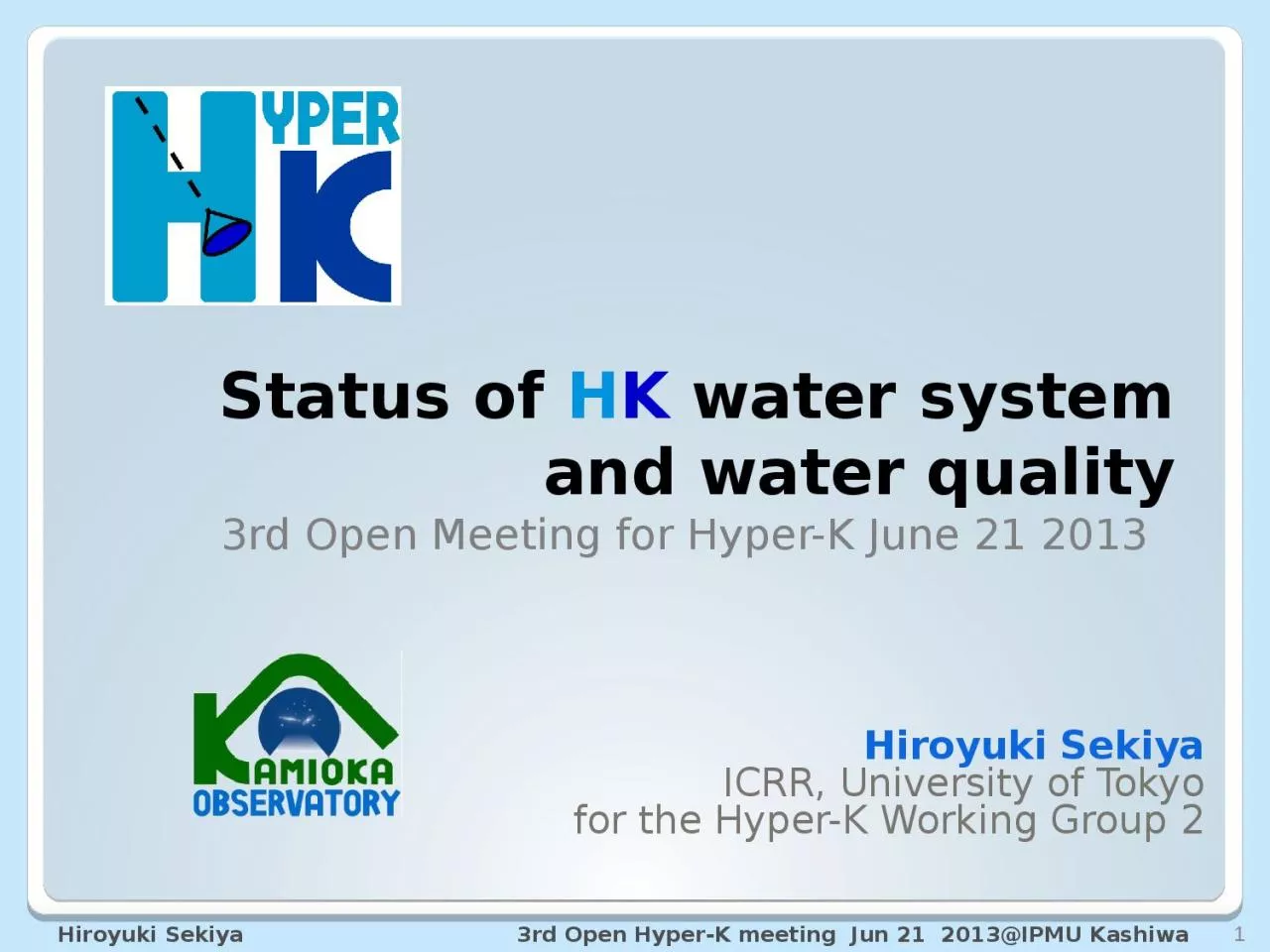
3rd Open Meeting for HyperK June 21 2013 1 Hiroyuki Sekiya ICRR University of Tokyo for the HyperK Working Group 2 Targets of WG2 Source water in the mountains Tochibora and ID: 932138
Download Presentation The PPT/PDF document "Status of H K water system and water q..." is the property of its rightful owner. Permission is granted to download and print the materials on this web site for personal, non-commercial use only, and to display it on your personal computer provided you do not modify the materials and that you retain all copyright notices contained in the materials. By downloading content from our website, you accept the terms of this agreement.
Slide1
Status of
HK water system and water quality3rd Open Meeting for Hyper-K June 21 2013
1
Hiroyuki
SekiyaICRR, University of Tokyofor the Hyper-K Working Group 2
Slide2Targets of WG2 Source water in the mountainsTochibora and Mozumi
Ultra pure water for supplying Water system designWater in the tankWater flow designGd water option
Mark’s talk 2
Slide3Source Water for Hyper-K3Tochibora
is already reported.Our demand (>300m3/h) is filled.Mozumi is not investigated officially yet.
Slide4Atotsu water stream4
45
40302515105 0
2035
m3/min.
Slide5In additionMore than 300m3/h spring in KAGRA tunnel
5
Slide6Hyper-K water system Cost estimation of the Revised design
6
Slide7Compressor
Dryer
0.3
m
m filterBufferH2O,CO2 remover20oCCharcoal0.1mm filter0.01mm filter0.01mm filter-40oCCharcoalBuffer10mm filterBuffer CO2 remover
Buffer
1
m
m filter
HK Tank
Rn
Free Air generator (400Nm
3
/h)
Water Purification System
0.24kt/h for initial supply
Mine water
RO
DI(MB)
DI(CP)
UV
MD
UF
T controller
1
.2kt/h for recirculation
purge
purge
purge
NO RO
Tochibora
plan
Slide8Compressor
Dryer
0.3
m
m filterBufferH2O,CO2 remover20oCCharcoal0.1mm filter0.01mm filter0.01mm filter-40oCCharcoalBuffer10mm filterBuffer CO2 remover
Buffer
1
m
m filter
HK Tank
Rn
Free Air generator (400Nm
3
/h)
Water Purification System
0.3kt/h for initial supply
Mine water
RO
DI(MB)
DI(CP)
UV
MD
UF
T controller
1
.2kt/h for recirculation
purge
purge
purge
Mozumi
plan
CO2 remover
RO
DI(MB)
purge
purge
NO RO
Slide9reject (drain)
reject (drain)
mine water
drain
reject
Primary pump
filter
filter
RO-1 pump
RO-2
pump
RO water tank
post RO
pump
RO-2
RO-1-1
vacuum degasifier
RO-3
reject
RO-3 pump
Ion exchanger 1/2
UV
sterilizer
purified water
s
upply pump A/B
A
B
SK
tank
ultra filter
membrane
degasifier
reject
550
Rn
-free-air
dissolving tank
PI-1
PI-2
PI-3
PI-8
PI-9
PI-A
PI-B
strainer
FI-1
FI-2
PI-5
PI-11
PI-18
FI-10
FI-101
PI-20
TIA-2
FI-6
FI-7
FI-204
FI-5
FI-3
FP-4
FP-5
FI-202
RT-3
RT-4
RT-2
RT-1
CIA-1
CIA-6
CIA-2
CIA-3
CIA-4
TI-101
CV-1
ID
bottom
FI-ID
CIA
CV-2
v94
700
compensation pump
strainer
UF reject tank
HE1
reject
HE3
reject
UF reject pump
return
pump
HE4
PI-C
RO-1-2
Super-K water system
filter
Slide10With or without RO?For prolong the lifetime of UFsAt the beginning of the recirculation, UFs may be clogged frequently.Initial cost vs. running cost
MFU
FNFRODI
Slide11Design with RO11
Slide12Layout
3 stagesRoom for Gd option12
Slide13Cost estimation13
Difference from previous estimation
ROIncreased UV sterilizer
SK-type MD 49.35 O
ku-Yen
Slide14Consideration of running cost14
w/ROw/o RO
Initial costRunning costAbout ROAfter 5 years of running, w/RO system will gain cost merit.3.5M$0$
1.6M$
2.3M$
Slide15Plumbing from water system to tanks
Slide16Cost estimation16
1.05 Oku-Yen
Slide1717
Plumbing in the tanks
Cost is already included in the TANK
Additional inlets/
oultels at 5 levels of side wall for: future activities to prevent stagnationrecirculation during initial filling to prevent bacteria from growing (180days!)
Slide18Water Flow simulation updates
One compartment for the first step
Software:ANSYS GAMBIT2.4.1+Fluent13.0
Slide19Water
inlets & outlets conditionsEqually distributed per top/bottom cross section
Top and bottom pipes only
Slide20ID & OD ConditionsID & OD are dealt as completely separated containers.20
Inner detectorOuter detectorVolume
370,000m389,000m3Flow rate96.7t/h23.3t/hNumber of inlets (outlets) 184Flow rate / inlet (outlet)5.375.82
Because of its symmetrical shape, only 1/4 volume is considered for the
simulation.1,400,000 mesh(xy, and yz symmetry)
Slide21Temperature conditionCooling water
10.5oC Supplying water 13.0oC
Top level rock 16.7oCBottom level rock 17.7oC
Slide22Other heat source conditions Unlike SK, electronics(HV, QBee,..) are also in the tank.The heat from compensation coil depends on the direction of the tank.
47.4kW
AreaFor one compartment
Slide23Full treatment simulation This is like SK… LowE oriented tuning.Bottom convection and top stagnation.
TemperatureID ¼
supply: bottom, return: top
Slide24Inverse operation This is atmpd/t2k oriented tuning.Whole convection uniform detector
TemperatureID ¼
Supply cold water to the top, return: bottom
Slide25Time evolution
25
Not yet
10 days
20 days30 days40 dayssupply: bottom, return: top Supply cold water to the top, return: bottom
Slide26Inlet pipe shape simulation SK inlet (thickness is unknown) Very difficult…
26
4mm thick pipe caseThin pipe case
Slide27ConclusionHyper-K water system was re-designed w/RO.For both Mozumi and Tochibora
optionsRough cost estimations are finishedProgress on the water flow simulation. Super-K flow is reproduced in Hyper-K tank.Started to estimate the effects of inlet pipe shapes.Working on detail simulations.SK flow in SK tank? For the validation of the simulation.Using side wall inlets/outlets
27
Slide28SK mesh for the flow simulation28