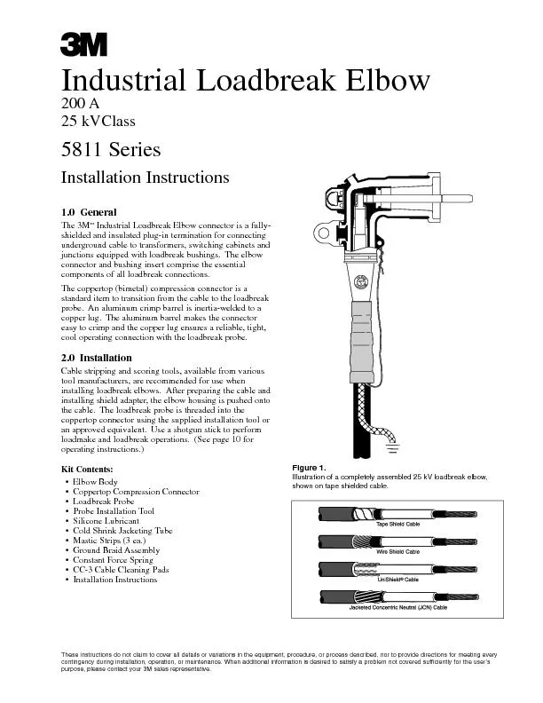
/
5811 Series1.0GeneralIndustrial Loadbreak Elbow connector is a fully-u 5811 Series1.0GeneralIndustrial Loadbreak Elbow connector is a fully-u

5811 Series1.0GeneralIndustrial Loadbreak Elbow connector is a fully-u - PDF document

alida-meadow
alida-meadow . @alida-meadow
Follow
405 views
Uploaded On 2016-04-29

5811 Series1.0GeneralIndustrial Loadbreak Elbow connector is a fully-u - PPT Presentation

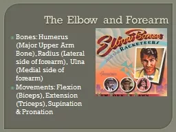
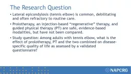
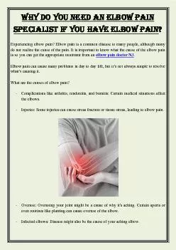
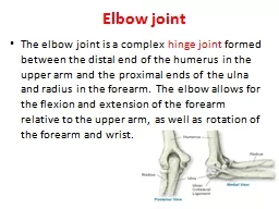
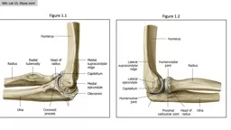
These instructions do not claim to cover all details or variations in the equipment procedure or process described nor to prcontingency during installation operation or maintenance When addition ID: 298141

These instructions not claim

Share:

Link:

Embed:

Download Presentation from below link

Download Pdf The PPT/PDF document "5811 Series1.0GeneralIndustrial Loadbrea..." is the property of its rightful owner. Permission is granted to download and print the materials on this web site for personal, non-commercial use only, and to display it on your personal computer provided you do not modify the materials and that you retain all copyright notices contained in the materials. By downloading content from our website, you accept the terms of this agreement.


Presentation Transcript

5811 Series1.0GeneralIndustrial Loadbreak Elbow connector is a fully-underground cable to transformers, switching cabinets andjunctions equipped with loadbreak bushings.The elbowstandard item to transition from the cable to the loadbreakprobe.An aluminum crimp barrel is inertia-welded to acopper lug.The aluminum barrel makes the connectorcool operating connection with the loadbreak probe. 2.0InstallationCable stripping and scoring tools, available from variousinstalling loadbreak elbows.After preparing the cable andinstalling shield adapter, the elbow housing is pushed ontothe cable.The loadbreak probe is threaded into thean approved equivalent.Use a shotgun stick to performloadmake and loadbreak operations.(See page 10 for¥Elbow Body¥Coppertop Compression Connector¥Loadbreak Probe¥Probe Installation Tool¥Silicone Lubricant¥Cold Shrink Jacketing Tube¥Mastic Strips (3 ea.)¥Ground Braid Assembly¥Constant Force Spring¥CC-3 Cable Cleaning Pads¥Installation Instructions These instructions do not claim to cover all details or variations in the equipment, procedure, or process described, nor to prcontingency during installation, operation, or maintenance. When additional information is desired to satisfy a problem not covered sufficiently for the userÕspurpose, please contact your 3M sales representative. Illustration of a completely assembled 25 kV loadbreak elbow, 2Installation Notes: ¥Cable description (check kit selection table on page 3 ¥Crimping Tool (check crimp chart on page 9) ¥Location ¥Installation comments Kit No.Insulation Diameter Range25kV (AWG/kcmil)100%133%(260 mils)(320 mils)Inches (mm)Stranded5811-B*0.700Ð0.91025811-B-3(17.8Ð23.1)5811-B-225811-C*1Ð3/05811-C-20.850Ð1.10025811-C-1(21.6Ð27.9)15811-C-1/01/05811-C-2/02/05811-C-3/03/05811-D*4/0Ð2505811-D-2/01.040Ð1.2502/05811-D-3/0(26.4Ð31.8)3/05811-D-4/04/05811-D-250250 *Kit without compression connector.Table 1.Kit Selection Table for 25 kV Class 3.1Check to be sure cable size fits within the kit range as shown in Table 1, page 3.¥Remove cable jacket for 83.2Remove metallic tape shield, leaving 1" (32 mm) exposed beyond cable jacket.(If necessary to prevent the tapeshield from unwinding, temporarily hold down end of shield with a wrap of vinyl electrical tape.)¥Remove semi-con (insulation shield), leaving 2" (60 mm) beyond cable jacket.¥Remove cable insulation for 2¥Place a " (3 mm) bevel on end of cable insulation, to ease installation.3.3Remove white liners from one mastic strip and apply one wrap around cable jacket " (13 mm) from edge.Applywith light tension.Cut off excess mastic.¥Position preformed ground braid with long leg along cable jacket as shown, with braid solder block centered on¥Wrap short leg of ground braid around cable metallic tape shield for one complete wrap.Trim excess to eliminate overlap.(Remove temporary wrap of vinyl tape if applicable.)3.4Secure ground braid to metallic tape shield with constant force spring.Wrap spring in same direction as ground braid,as shown.Cinch (tighten) the last wrap of spring.¥Remove liners from second mastic strip and apply one wrap over solder block and previously applied mastic strip.Cut off excess mastic.¥Apply two half-lapped layers of vinyl tape over mastic, constant force spring and exposed tape shield.3.0Preparation of Tape Shield Cable3.13.23.33.4 yyyy yy yy yy yyyy 4.1Check to be sure cable size fits within the kit range as shown in Table 1, page 3.¥Remove cable jacket for 84.2Cut-off shield wires, leaving 1" (32 mm) exposed beyond cable jacket.¥Remove semi-con (insulation shield), leaving 2" (60 mm) beyond cable jacket.¥Remove cable insulation for 2¥Place a " (3 mm) bevel on end of cable insulation, to ease installation.4.3Remove white liners from one mastic strip and apply one wrap around cable jacket " (13 mm) from edge.Applywith light tension.Cut off excess mastic.¥Position preformed ground braid with long leg along cable jacket as shown, with braid solder block centered on ¥Wrap short leg of ground braid around cable wire shield for one complete wrap.Trim excess to eliminate overlap.4.4Secure ground braid to wire shield with constant force spring.Wrap spring in same direction as ground braid, asshown.Cinch (tighten) the last wrap of spring.¥Remove liners from second mastic strip and apply one wrap over solder block and previously applied mastic strip.Cut off excess mastic.¥Apply two half-lapped layers of vinyl tape over mastic, constant force spring and exposed wire shield.4.0Preparation of Wire Shield Cable4.14.24.34.4 yy yy yyyy yyyy yyyy 5.1Check to be sure cable size fits within the kit range as shown in Table 1, page 3.Note:UniShield cable has compact conductor.¥Mark cable jacket 7" (178 mm) from cable end (a temporary wrap of vinyl tape can be used as a marker).¥Use a needle-nose pliers to pull each individual drain wire out through cable semi-con jacket, back to previouslyapplied mark.(Remove vinyl tape if it was used as a temporary marker.)Cut off wires leaving 1exposed.Carefully bend drain wires back along cable jacket.Keep wires separated and spaced around cable.5.2Temporarily install constant force spring over cable semi-con jacket, 5" (149 mm) from cable end.¥Score semi-con jacket (cut 80% through) at edge of spring.Remove jacket sections by carefully pulling againstspring.Use care not to lift (bell) the end of the jacket.¥Remove constant force spring (save spring for later ground installation.)5.3Remove cable insulation for 2" (54 mm) from edge.¥ Place a 1/8Ó (3 mm) bevel on the end of cable insulation to ease installation.¥ Remove white liners from one mastic strip and apply one wrap around cable semi-con jacket 2" (73 mm) from edge. Apply with light tension. Cut off excess mastic.¥Position preformed braid with long leg along cable jacket as shown, with braid solder block centered on previously¥Wrap short leg of ground braid around bent back drain wires for 1 complete wrap.Trim excess to eliminate overlap.5.4Secure ground braid to drain wires with constant force spring.Wrap spring in same direction as ground braid, asshown.Cinch (tighten) the last wrap of spring.¥Remove liners from 2nd mastic strip and apply 1 wrap over solder block and previously applied mastic strip.Cutoff excess mastic.¥Apply 2 half-lapped layers of vinyl tape over mastic, constant force spring and exposed drain wires.5.0Preparation of UniShield5.15.25.35.4 yy yy yy yy yyyy yy Note:The ground braid assembly and constant force spring are not used for this application.6.1Check to be sure cable size fits within the kit range as shown in Table 1, page 3.¥Remove cable jacket for 86.2Remove white liners from 1 mastic strip and apply 1 wrap around cable jacket " (13 mm) from edge.Apply withlight tension.Cut off excess mastic.¥Bend neutral wires back over mastic strip and secure to cable jacket 2" (51 mm) from jacket end.Keep wires6.3Remove white liners from 2nd mastic strip and apply 1 wrap over neutral wires and previously applied mastic strip.¥Press neutral wires into mastic by applying 2 highly stretched half-lapped layers of vinyl tape over mastic and 6.4Continue cable preparation.¥Remove semi-con (insulation shield) for 5" (60 mm) exposed beyond cable jacket.¥Remove cable insulation for 2¥Place a " (3 mm) bevel on end of cable insulation to ease installation.6.0Preparation of Jacketed Concentric Neutral Cable6.16.26.36.4 7.1Clean the exposed conductor using a wire brush.Place the coppertop (bimetal) connector on the conductor.Makesure threaded hole in connector faces the apparatus bushing.Crimp the connector in place using a tool and diecombination listed in Table 2.Start crimping just below the knurled line and rotate each successive crimp to preventbowing.Do not overlap crimps.Place as many crimps on the connector as will fit.¥Clean excess inhibitor grease from coppertop connector by wiping toward threaded eye.¥Clean cable insulation with solvent pad(s) from 3M CC-3 Cable Cleaning Kit.Do Not allow solvent to touch cableNote:If use of an abrasive cloth is necessary, use an electrical grade (non-conductive) abrasive.A120 gritabrasive is recommended.7.2Slide Cold Shrink assembly over cable with loose core end leading (away from cable end).Temporarily position itjust beyond prepared cable end.7.3Apply a thin coating of silicone lubricant to the cable insulation.¥Clean and lubricate the cable entrance of the elbow.¥Place elbow on cable.With a twisting motion, push elbow onto cable until threaded eye of coppertop connector isaligned with the elbow.7.4By hand, thread loadbreak probe into threaded eye of coppertop connector.When tight, use the provided installationtool to properly torque the loadbreak probe.Proper torque is applied when the tool achieves a 180Note:If a different installation tool is used it must apply a torque of 110 in-lbs to achieve proper installation.7.0Elbow and Loadbreak Probe Installation7.17.27.37.4 7.0Elbow and Loadbreak Probe Installation Step 1/2" (13 mm) Mastic Strip Clean and Lubricate Grounding Tab Step Cold Shrink Tubing 7.57.6 7.5Remove white liners from remaining mastic strip andapply around base of elbow, " (13 mm) from step asshown.Apply 1 layer of vinyl tape over mastic.7.6Align Cold Shrink rubber tube (not core) with step ofelbow.Remove core by pulling and unwinding thecore counter-clockwise.¥Attach 14 AWG ground lead (from ground braidassembly) to the elbow grounding eye.Connect ground braid to system ground.(For jacketedgrounding eye, and connect remaining neutral bundle tosystem ground.)4 AWG through 2/0 Stranded3/0 AWG through 250 kcmil StrandedToolY34Y35 OR Y39MD6Y34Y35 OR Y39MD6A243U243UBGW243WBGU247U247U467W247A25ARU25ARTU687BGW687A27ARU27ARTToolUT-3UT-5UT-15UT-5UT-15"TV54 HTV66 Tool0H-1, H-20H-1, H-2"572737747737747Tool12A12ADieB24 EAB39 EAAnderson ToolVC-5, VC-6VC-5, VC-68A10A Table 2. 8.0Operating Instructions8.1Before Loadmake orLoadbreak Operation:Area must be clear of obstructions or contaminants that would interfere with the operation of the connector. This positionshould allow you to establish firm footing and enable you to grasp the shotgun stick securely, maintaining positive controlover the movement of the loadbreak connector before, during and directly after the operating sequence. Because of thecontrol, speed and force required to engage or disengage the elbow, certain operating positions are more advantageous thanenergized. Do not connect two different phases of a multiple-phase system. Before closing a single-phase loop, make certain8.2Loadmake Operation¥Area must be clear of obstructions or contaminants that would interfere with the operation of the loadbreak elbow.¥Securely fasten a shotgun stick to the pulling eye.¥Place the loadbreak elbow over the bushing, inserting the loadbreak probe into the bushing until the first slight resistance i¥Immediately thrust the elbow onto the bushing with a fast, firm, straight motion, with sufficient force to latch the elbowto the bushing.8.3Fault Close¥It is not recommended that operations be made on known faults.¥If a fault is experienced, both the elbow connector and the bushing must be replaced.8.4Loadbreak Operation¥Securely fasten a shotgun stick to the pulling eye.¥Without exerting any pulling force, slightly rotate the connector clockwise in order to break surface friction between the¥Withdraw the connector from the bushing with a fast, firm, straight motion, being careful not to place the connector near¥Place connector on appropriate accessory device, following the operating instructions for that accessory. 11 3M is a registered trademark of 3M.UniShieldis a registered trademark of BICC Cables.Note:The core material being removed from the Cold Shrink Tube is mixed polymers and can be recycled with other waste.IMPORTANT NOTICEBefore using this product, you must evaluate it and determine if it is suitable for your intended application. You assume all associated with such use.Warranty; Limited Remedy; Limited Liability. This product will be free from defects in material and manufacture as of the date ofpurchase. 3M MAKES NO OTHER WARRANTIES INCLUDING, BUT NOT LIMITED TO, ANYIMPLIED WARRANTYOFMERCHANTABILITYOR FITNESS FOR APARTICULAR PURPOSE.If this product is defective within the warranty period stated above,your exclusive remedy shall be, at 3Ms option, to replace or repair the 3M product or refund the purchase price of the 3M product. where prohibited by law, 3M will not be liable for any loss or damage arising from this 3M product, whether direct, indirect, sincidental or consequential regardless of the legal theory asserted.Electrical Products Division6801 River Place Blvd.Austin, TX 78726-9000800/245-3573Printed on 50% recycled paperLitho in USAwww.3M.com/elpdwith 10% post-consumer