/
DLR REFINES AIRCRAFT CABINS BY ANALYSING NOISE PATHSCASE STUDYDLR is G DLR REFINES AIRCRAFT CABINS BY ANALYSING NOISE PATHSCASE STUDYDLR is G

DLR REFINES AIRCRAFT CABINS BY ANALYSING NOISE PATHSCASE STUDYDLR is G - PDF document

alida-meadow
alida-meadow . @alida-meadow
Follow
393 views
Uploaded On 2016-07-20

DLR REFINES AIRCRAFT CABINS BY ANALYSING NOISE PATHSCASE STUDYDLR is G - PPT Presentation

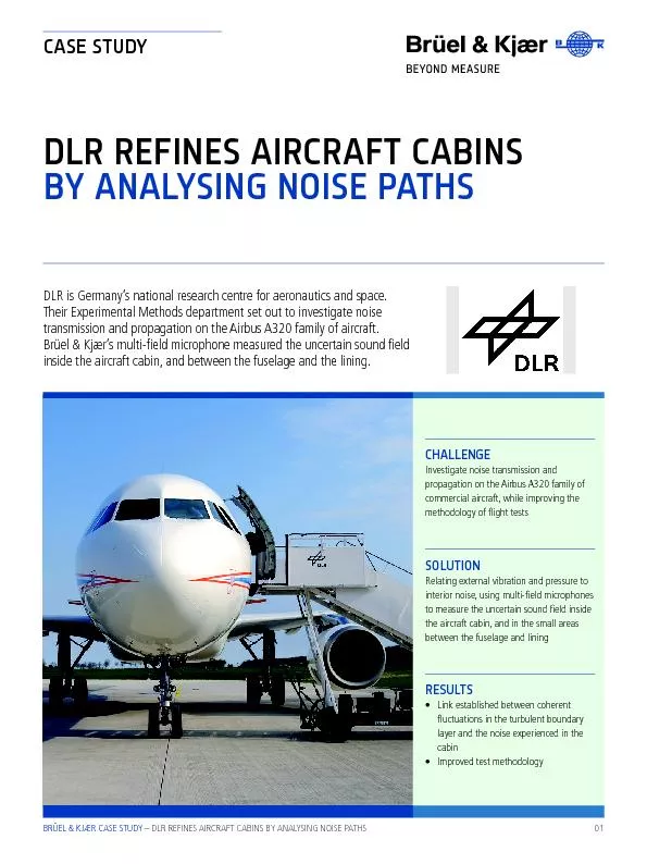
01 Investigate noise transmission and propagation on the Airbus A320 family of commercial aircraft while improving the RESULTSLink established between coherent uctuations in the turbulent boundary ID: 412654

01 Investigate noise transmission and propagation

Share:

Link:

Embed:

Download Presentation from below link

Download Pdf The PPT/PDF document "DLR REFINES AIRCRAFT CABINS BY ANALYSING..." is the property of its rightful owner. Permission is granted to download and print the materials on this web site for personal, non-commercial use only, and to display it on your personal computer provided you do not modify the materials and that you retain all copyright notices contained in the materials. By downloading content from our website, you accept the terms of this agreement.


Presentation Transcript

01 DLR REFINES AIRCRAFT CABINS BY ANALYSING NOISE PATHS CASE STUDY DLR is Germany’s national research centre for aeronautics and space. Their Experimental Methods department set out to investigate noise transmission and propagation on the Airbus A320 family of aircraft. Kjær’s multi-eld microphone measured the uncertain sound eld inside the aircraft cabin, and between the fuselage and the lining. CHALLENGE Investigate noise transmission and propagation on the Airbus A320 family of commercial aircraft, while improving the methodology of ight tests RESULTS • Link established between coherent uctuations in the turbulent boundary layer and the noise experienced in the cabin • SOLUTION Relating external vibration and pressure to interior noise, using multi-eld microphones to measure the uncertain sound eld inside the aircraft cabin, and in the small areas between the fuselage and lining BRÜEL & KJÆR CASE STUDY – DLR REFINES AIRCRAFT CABINS BY ANALYSING NOISE PATHS we don’t know if the sound-eld is diffuse or something else,” says Dr Spehr. “We also put microphones between the aircraft structure and the lining. And what are the conditions like there? We don’t know, so we use the multi-eld microphone,” says Dr Spehr. SOLUTION Multi-eld microphones were placed along the longitudinal section of the aircraft, facing upwards in the positions taken by the passengers, in an F-frame array that covered a cross-section of the aircraft. DLR also developed their own arrays of mul - ti-eld microphones for closed test sections. “The area is small, so we couldn’t use a normal preamplier,” says Dr Spehr. ”Because they are smaller than ½”microphones, mul - ti-eld microphones are easy to use in such a conned space.” BACKGROUND As Germany’s national space agency, DLR has responsibility for the forward planning and implementation of the German space pro - gramme, as well as international representa - tion of Germany’s interests. Approximately 7000 people work for DLR’s 32 institutes, at 16 locations in Germany, as well as ofces in Brussels, Paris, Singapore, and Washington D.C. DLR’s facility at Göttingen employs more than 400 experts in the foundation- and applica - tion-oriented eld of aviation research. CHALLENGE Together with other DLR departments, DLR’s Experimental Methods department undertook the rst of three ight tests with Airbus Ham - burg in May 2011, to simultaneously measure excitation, transmission, and the noise propa - gation into the cabin of an A320. “Airbus asked us what the optimal aircraft noise level is,” explains Dr Carsten Spehr of the Institute of Aerodynamics and Flow Technology. “And of course this is difcult to answer. Other passengers make noise, so it’s actually quite pleasant to have a nice, deep noise that masks the noise of the other pas - sengers. So the research we do here is to nd the optimal cabin comfort for planes.” “The purpose was not to improve existing aircraft, as the A320 is good and sells well – but the next generation will be different. So we needed an understanding of the physics, and how the noise gets into the cabin,” says Dr Spehr. The intention was also to improve this kind of 02 ight test. Since the 1980s, ight tests have normally used different aircraft at different times and can’t correlate between them, as they don’t have the same database. So here, DLR were trying to improve on this with a new, consistent method. Challenging measurement ‘rooms’ The main issues for interior acoustics are cooling system noise, fan noise, the turbulent boundary layer, and overall airframe noise. “There are two ways for the acoustic energy to come from outside to inside: either through the shock mounts and the structural coupling, or through the air between the structure and the lining,” says Dr Spehr. Microphones help to distinguish between these different sources. However, aircraft are difcult ‘rooms’ for acoustic measurements because they are reverberant, long and thin, and give a very different acoustic response depending on the direction and location of the measurement. “For these kinds of tests, The cradle of aerodynamics DLR Göttingen is the cradle of modern aerodynamics. In 1907 the rst state-run research facility for aeronautics was founded here. Many foundations of modern aviation were researched in Göttingen. Ludwig Prandtl (pictured) de - veloped the aerofoil theory, Hans Pabst von Ohain tested the forerunner of the rst jet engine, and the swept wing was invented – a prerequisite for modern aviation. Most of the wind tunnels in the world are based on the Göttingen type. “THE A320 IS GOOD AND SELLS WELL – BUT THE NEXT GENERATION WILL BE DIFFERENT. SO WE NEEDED AN UNDER - STANDING OF THE PHYSICS, AND HOW THE NOISE GETS INTO THE CABIN.” Dr Carsten Spehr, Institute of Aerodynamics and Flow Technology BRÜEL & KJÆR CASE STUDY – DLR REFINES AIRCRAFT CABINS BY ANALYSING NOISE PATHS 03 DLR measured the transfer paths with accel - erometers, and the turbulent boundary layer with pressure sensors placed in three dummy windows. “If you measure aerodynamic ow distributions then you want a high spatial reso - lution, which means you want to have a really small surface. We measured the ow in the turbulent boundary layer with a pressure sen - sor recessed behind a hole of 0.3 mm. These pressure sensors have a low dynamic range, but you can measure even high pressure, and they are very small,” explains Dr Spehr. In all, the testing used 65 multi-eld micro - phones, 154 accelerometers and 30 pressure sensors. Multi-eld microphone There were no problems setting up the mul - ti-eld microphones. As Dr Spehr says, “They use a standard CCLD input, so you know that there are no problems. Sensitivity is usually an issue, as normally ¼” microphones are not so sensitive, so it was really nice to have small microphones with the same sensitivity as ½” microphones.” “Aircraft are reverberant, and not the same in different directions, where there are different dimensions, but we didn’t have to think about that. We knew we would make an error in every direction, so to minimise this error it is best to have an omni-directional microphone that doesn’t care about that.” “When doing these kinds of tests, there are also sometimes issues with electromagnetic interference, but with the titanium build, we didn’t have any problems at all, even on the inside of an aircraft where there is a 400 Hz electrical eld – which is a quite strong – we didn’t have to even think about it.” RESULTS By combining sound measurement results with those from pressure sensors and accelerom - eters, the tests established the link between coherent uctuations in the turbulent boundary layer and the noise experienced in the cabin. “WE ALSO PUT MICROPHONES BETWEEN THE AIR - CRAFT STRUCTURE AND THE LINING. AND WHAT ARE THE CONDITIONS LIKE THERE? WE DON’T KNOW, SO WE USE THE MULTI - FIELD MICROPHONE.” Dr Carsten Spehr, Institute of Aerodynamics and Flow Technology Distribution of microphones in the cabin Distribution of multi-eld microphones in the cavities between the cabin and the fuselage Three false windows held the pressure sensors in the airow, recessed by 0.3 mm Multi-eld Microphone benets Easy to t into small areas • Don’t have to think of the angle that the sound is coming from, or the sound eld • • Multi-eld microphones can accurately measure sound from any direction, and in any type of sound eld BRÜEL & KJÆR CASE STUDY – DLR REFINES AIRCRAFT CABINS BY ANALYSING NOISE PATHS Copyright © Brüel & Kjær. All rights reserved. Brüel & Kjær Sound & Vibration Measurement A/S DK-2850 Nærum · Denmark Telephone: +45 77 41 20 00 · Fax: +45 45 80 14 05 · www.bksv.com · info@bksv.com Local representatives and service organisations worldwide www.bksv.com/ casestudies BN 1622 – 12 2019-08 In the aerodynamic part of the measurement – the turbulent boundary layer – the coherence in acoustic waves is quite large, which as Dr Spehr explains, is signicant. “If you have coherent uctuations, then they can excite the fuselage, and that can create noise you can really hear.” “At four different speeds at the same ight level in cruise conditions, you would expect 1 mm of aluminium to have the same transmis - sion. However, this is not the case. There is a 3 dB difference with just a 10 percent speed Increase,” says Dr Spehr. CONCLUSION “If you consider this in the airframe design stage, you can adapt the modal distribution of your fuselage to the turbulent boundary layer and ensure that you don’t have this coinci - dence. So if you know that this is your normal speed, then you can adapt your fuselage and make sure that it is not in coincidence with the hydrodynamic coincidence outside. So the interesting point from this is that even without adding mass or anything else, you can really change the behaviour,” explains Dr Spehr. “It was a nice ight test, and the analysis is still ongoing,” says Dr Spehr. “I have had some more requests because it was such a success.” Convincing stakeholders to buy equipment is an issue, so when DLR was procuring their multi-eld microphones it was important that stakeholders were convinced of the advan - tages, and of their high quality. As Dr Spehr says, “It doesn’t make sense to have cheap microphones in a ight test that costs millions of Euros, so the multi-eld microphones are good value.” The multi-eld microphones were an optimal solution for DLR: “The only possible alterna - tive to a multi-eld microphone would be to use ½” microphones, where we would then have to consider whether it was a free-eld condition or any unknown condition. So it was perfect that at the same time that we made the technical requirements for the ight test, Brüel & Kjær came out with the multi-eld microphone, so we didn’t have to search long before our answer came along. For cabin noise the multi-eld microphone is perfect.” DLR’s wind tunnel is transonic, meaning up to 1.5 Mach, which is fast and loud. They need micro - phones with a high dynamic range that can operate at 176-180 dB. “We have different types of mikes,” says Dr Spehr. “Mostly ¼” mikes from Brüel & Kjær, including a special version designed for measuring in a cryogenic environment (100 Kelvin). This has been used in a great research project. A colleague of mine developed a new measurement technique in that, so it is a great success story.” “NORMALLY ¼” MICROPHONES ARE NOT SO SENSITIVE, SO IT WAS REALLY NICE TO HAVE SMALL MICROPHONES WITH THE SAME SENSI - TIVITY AS ½” MICROPHONES. WE DIDN’T HAVE TO SEARCH LONG BEFORE OUR ANSWER CAME ALONG. FOR CABIN NOISE THE MULTI - FIELD MICROPHONE IS PERFECT.” Dr Carsten Spehr, Institute of Aerodynamics and Flow Technology