/
Rev  WK Page  of  MT TUTORIAL Decoupling Techniques WHAT IS PROPER DECOUPLING AND WHY Rev  WK Page  of  MT TUTORIAL Decoupling Techniques WHAT IS PROPER DECOUPLING AND WHY

Rev WK Page of MT TUTORIAL Decoupling Techniques WHAT IS PROPER DECOUPLING AND WHY - PDF document

alida-meadow
alida-meadow . @alida-meadow
Follow
537 views
Uploaded On 2014-12-14

Rev WK Page of MT TUTORIAL Decoupling Techniques WHAT IS PROPER DECOUPLING AND WHY - PPT Presentation

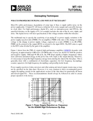
0 0309 WK Page 1 of 14 MT101 TUTORIAL Decoupling Techniques WHAT IS PROPER DECOUPLING AND WHY IS IT NECESSARY Most ICs suffer performance degradation of some type if there is ripple andor noise on the power supply ID: 23617

0309 Page

Share:

Link:

Embed:

Download Presentation from below link

Download Pdf The PPT/PDF document "Rev WK Page of MT TUTORIAL Decoupling..." is the property of its rightful owner. Permission is granted to download and print the materials on this web site for personal, non-commercial use only, and to display it on your personal computer provided you do not modify the materials and that you retain all copyright notices contained in the materials. By downloading content from our website, you accept the terms of this agreement.


Presentation Transcript

Rev.0, 03/09, WK WHAT IS PROPER DECOUPLING AND WHY IS IT NECESSARY? ) degrades with Page 2 of 14 electrolytic capacitors which act as charge reservoirs to surface mount ceramic capacitors connected directly to the power supply pins of the IC. All r this connection to minimize additional series Ferrite beads (nonconductive ceramics manufactured from the oxides of nickel, zinc, manganese, ferrites becomes resistive (high Q). Ferrite impedance is a function of material, operating turns, size, shape, and temperature. The ferrite beads may not always be necessary, but they will add extra high frequency noise the beads never saturate, especially when op amps are driving high output currents. When a ferrite saturates it becomes nonlinear and loses its filtering properties. Note that some ferrites, even before full saturation occurs, can be nonlinear. Therefore, if a ling are summarized in Figure 2. A large electrolytic capacitor (typically 10 µF –100 µF) no more than 2 in. away from the chip.The purpose of this capacitor is to be a reservoir of charge to supply the instantaneous charge requirements of the circuits locally sothe charge need not come through the inductance of the power trace.A smaller cap (typ. 0.01 µF –0.1 µF) as physically close to the power pins of the chip as is possible.The purpose of this capacitor is to short the high frequency noise away from the chip.All decoupling capacitors should connect to a large area low impedance ground plane through a via or short trace to minimize inductance.Optionally a small ferrite bead in series with the supply pin.Localizes the noise in the system.Keeps external high frequency noise from the IC.Keeps internally generated noise from propagating to the rest ofthe system. Page 3 of 14 REAL CAPACITORS AND THEIR PARASITICS Figure 3 shows a model of a non-ideal capacitor. ESR), appears in series with the capacitor and represents the resistance of the capacitor leads and plates. r Equivalent Circuit Includes Parasitic Elements ries inductance, or ESL), models together form a simplified model of a phenomenon known as dielectric absorption, or DA. When a capacitor isapplication, such as a sample-and-hold amplifier (SHA), DA can cause errors. In a decoupling application, however, the DA of a capimpedance of a capacitor will decrease monotonically as frequency is increased. In actual practice, the ESR causes the impedance plot to flimpedance will start to rise due to the ESL of the capacitor. The location and width of the "knee" will vary with capacitor construction, dielectric and value. This is why we often see larger value capacitors paralleled with smaller values. The smaller value capacitor will typically have lower performance of the parallel combination over a wider frequency range. C ESRESL RDACDARS Page 4 of 14 The self-resonant frequency of the capacitor is the frequency at which the reactance of the reactance of the ESL (ESL). Solving this equality for the CESL2⋅π. Eq. 1 All capacitors will display impedance curves which are similar in general shape to those shown. ral shape stays the same. The minimum impedance is determined by the ESR, and the high frequency region is determined by the ESL (which in turn is strongly affected by package style). TYPES OF DECOUPLING CAPACITORS of popular capacitors family provides an excellent, cost effective low-frequency filter component because of the wide range of values, a high capacitance-to-volume ratio, and a broad range of working voltages. It includes general-purpose aluminum from below 10 V up to about 500 V, and in size from 1 µF to seESL·C 10 m100 1k 10k 100k 1M 10M Aluminum Switching Type, 10VLow ESR Tantalum, 10VPolymer Tantalum, 4VSP-Cap (SL Series), 2VCeramic, 6.3V FREQUENCY (Hz) ESL = 1.6nHESL = 16nH ESR = 0Self-Resonant Frequency = 1 2 Page 5 of 14 s are polarized, and thus cannot withstand more than a volt or so of specific family design, electris not likely to be a major factor for basic "General purpose" aluminum electrolytic capacitors are not recommended for most decoupling applications. However, a subset of aluminum electrolytic capacitors ishundred kHz with low losses. This type of capacitor competes directly wd has the advantage of a much broader range of Solid tantalum electrolytic capacitors are generally limited to voltages of 50 V or less, with tantalums exhibit higher capacitance-to-volume ratios than do the aluminum switching electrolytlower ESR. They are generally more expensive than aluminum electrolytics and must be carefully applied with respect to surge and ripple currents. More recently, high performance aluminum electrolytic capacitors using organic or polymer electrolytes have appeared. These families of capacitors feature appreciably lower ESR and types, with an additional feature of minimal low-temperature ESR degradation. They special polymer APPLICATIONS DISADVANTAGES ADVANTAGES TECHNOLOGYHigh voltage, currentAudioCV product limitedNot popular in SMTHigh costHi Q in large sizesNo wearoutHigh voltageFilm (Polyester, Teflon, polypropylene, polystyrene, etc.Excellent for HF decouplingGood to 1GHzCV product limitedMicrophonicsC decreases with increasing voltageLowest ESR, ESLHigh ripple currentX7R good over wide Newest technologyCPU core regulatorsRapid degradation above 105°CRelatively high costLow ESRZ stable over tempRelatively small caseAluminum-Polymer, Special-Polymer,Poscap, Os-ConPopular in militaryConcern for tantalum raw material supplyFire hazard with reverse voltageExpensiveOnly rated up to 50VHigh CV product/sizeStable @ cold tempNo wearoutSolid TantalumConsumer productsLarge bulk storageTemperature related wearoutHigh ESR/sizeHigh ESR @ low tempHigh CV product/costLarge energy storageBest for 100V -400VAluminum Electrolytic,Switching Type.Avoid general purpose types APPLICATIONS DISADVANTAGES ADVANTAGES TECHNOLOGYHigh voltage, currentAudioCV product limitedNot popular in SMTHigh costHi Q in large sizesNo wearoutHigh voltageFilm (Polyester, Teflon, polypropylene, polystyrene, etc.Excellent for HF decouplingGood to 1GHzCV product limitedMicrophonicsC decreases with increasing voltageLowest ESR, ESLHigh ripple currentX7R good over wide Newest technologyCPU core regulatorsRapid degradation above 105°CRelatively high costLow ESRZ stable over tempRelatively small caseAluminum-Polymer, Special-Polymer,Poscap, Os-ConPopular in militaryConcern for tantalum raw material supplyFire hazard with reverse voltageExpensiveOnly rated up to 50VHigh CV product/sizeStable @ cold tempNo wearoutSolid TantalumConsumer productsLarge bulk storageTemperature related wearoutHigh ESR/sizeHigh ESR @ low tempHigh CV product/costLarge energy storageBest for 100V -400VAluminum Electrolytic,Switching Type.Avoid general purpose types Page 6 of 14 Ceramic, or multilayer ceramic (MLCC), is often the capacitor material of choice above a few MHz, due to its compact size and low loss. However, the characteristics of ceramic dielectrics varies widely. Some types are better than others for power Ceramic dielectric capacitors are available in values up to several µF in the high-K dielectric formulations of X7R. Z5U, and because it has less capacitance change as a function of dc bias voltage than the Z5U and Y5V ic constant formulation, and have nominally zero TC, plus a low voltage coefficient (unlike thlimited in available values to 0.1 µF or less, a more practical upper limit. Multilayer ceramic (MLCC) surfe increasingly popular for bypassing and filtering at 10 MHz or more, because their very low inductance design allows near optimum RF bypassing. In smaller values, ceramic chip caps havethese and other capacitors for hiIn general, film type applications where a very low capacitance vs. voltage coefficient is required. LOCALIZED HIGH FREQUENCY DECOUPLING RECOMMENDATIONS capacitor must be as close to the chip as onnecting trace will have a negative impact on the Filter(s) Require Decoupling via V+GND GROUNDPLANEDECOUPLINGCAPACITOR GND DECOUPLINGCAPACITOR GROUND PCBTRACEICIC SUPPLYTRACE POWERTRACE CORRECTINCORRECT OPTIONALFERRITE BEADS Page 7 of 14 this would be the most effective configuration. In the figure on the right, however, the extra inductance and resistance in the PCB trace will caueffectiveness of the decoupling scheme and may cause interference problems by increasing the enclosed loop. RESONANT CIRCUITS FORMED BY LC DECOUPLING NETWORKS In many decoupling applications, an inductor or capacitor, C, forms a resonant, or "tuned," circu that it shows marked LC2. Eq. 2 med by Power Line Decoupling The overall impedance of the decoupling network may exhibit peaking at Just how much peaking depends on the relative Q (quality factor) of the tuned circuit. The Q of a resonant circuit is a measure of R fL2 . Eq. 3 Normal trace inductance and typiwell above a few MHz. For example, 0.1 µF and 1 nH will resonate at 16 MHz. at 16 kHz. Left unchecked, this can present a resonance problem if this frequency appears on the power line. The effect can be minimized by lowering the Q of the circuit. This is most easily done by inserting a small resistance (~10 w as possible to minimize the IR drop across the resistor. An alternative to a resistor is a small ferrite bead which appears primarily resistive at the L1C1SMALL SERIES RESISTANCE CLOSE TO IC REDUCES QEQUIVALENT DECOUPLED POWER LINE CIRCUIT RESONATES AT: 1 0.1µF 0.1µF1µH R110 IC Page 8 of 14 The use of a ferrite bead rather than an inductor minimizes resonance problems because the circuit. Typical ferrite bead impedances are shown in Figure 8. Figure 8: Ferrite Bead Impedance Compared to a 1µH Inductor The response of simple LRC decoupling networks can be easily simulated using a SPICE-based program such as National Instruments Multisim™, Analog Devices' Edition . A typical model of nd a simulated response in Figure 10. Courtesy: Fair-Rite Products Corp, Wallkill, NY(http://www.fair-rite.com) #73MATERIAL #43MATERIAL#64MATERIAL101001000FREQUENCY (MHz) 02040 1µH INDUCTOR Electrode Ferrite Core f ESL – ESLESR LOADGAIN 1 2f C1 2f C + ESR C Z = f ESL – 1 2f C1 2f C + ESR Z ESL LOAD 12f L ESR fP= 1 LC 1 2fP= 1 LC 1 2Z log flog fABOVE ASSUMES RLOAD� 10kNEGLECTS R0.1 0.01 FILTERGAIN ESL·C 1 2 fR Page 9 of 14 NI Multisim™ Analog Devices® Edition EFFECTS OF POOR DECOUPLING TECHNIQUES ON PERFORMANCE In this section we examine the ling on two fundamental components: an op amp and an ADC. , a 1.5 GHz high speed current feedback op amp. ing the evaluation board. The left-hand trace shows ght-hand trace shows the same response on the same board with the decoupling capacitors remo LOAD LOAD4nH100µH 1.6kHzESLL ESLL 20 log= –88dB 2f L ESR FILTERGAIN No decoupling Page 10 of 14 tion of frequency. Note that the PSRR falls to a relatively low value at the higher frequencies. This means that signals on the power line will circuits. Figure 13 shows the circuit used to measure the PSRR of y Rejection Ratio (PSRR) We will now examine the effect of proper and improper decoupling on a high performance data 14-bit, 105/125MSPS ADC. While a convey not have a PSRR specification, proper decoupling is still very important. Figure 14 shows the FFT output of uation board for the AD9445. Note the clean spectrum. Page 11 of 14 e AD9445 Evaluation Board . Note that there are multiple power and ground pins. This is done to lower the impedance e connected to AVDD1 (which is +3.3 V experiment, each pin has a ceramic decoupling cap. In addition, there are several 10 µF electrolytic capacitors as well. Page 12 of 14 Figure 16 shows the spectrum with the decoupling caps removed from the analog supply. as some intermodulation products (lower frequency components). st is removal of the decoupling capacitors. Again we used the AD9445 evaluation board to make the measurements. AD9445 Evaluation Board with Caps Removed from the Analog Supply Figure 17 shows the result of removing the decoupling caps from the digital supply. Again note rum. This experiment was run with the LVDS We can assume that the CMOS version would be worse because LVDS is less noisy than saturating CMOS logic. Page 13 of 14 AD9445 Evaluation Board with Caps Removed from the Digital Supply REFERENCES: Henry W. Ott, Noise Reduction Techniques in Electronic Systems, 2 Edition, John Wiley, Inc., 1988, ISBN: 0-471-85068-3. Paul Brokaw, "An IC Amplifier User's Guide to Decoupling, Grounding and Making Things Go Right for a Change", Analog Devices, AN-202 Paul Brokaw, "Analog Signal-Handling for High Speed and Accuracy," Analog Devices, AN-342 Jerald Graeme and Bonnie Baker,"Design Equations Help Optimize Supply Bypassing for Op Amps,"Electronic Design, Special Analog Issue, June 24, 1996, p.9. Jerald Graeme and Bonnie Baker, "Fast Op Amps Demand More Than a Single-Capacitor Bypass," Electronic Design, Special Analog Issue, November 18, 1996, p.9. Jeffrey S. Pattavina, "Bypassing PC Boards: Thumb Your Nose at Rules of Thumb," EDN, Oct. 22, 1998, p.149. Howard W. Johnson and Martin Graham, High-Speed Digital Design, PTR Prentice Hall, 1993, ISBN-10: 0133957241, ISBN-13: 978-0133957242. Ralph Morrison, Solving Interference Problems in Electronics, John Wiley, 1995, ISBN-10: 0471127965, ISBN-13: 978-0471127963 C. D. Motchenbacher and J. A. Connelly, Low Noise Electronic System Design, John Wiley, 1993, ISBN-10: 0471577421, ISBN-13: 978-0471577423. 10.Mark Montrose, EMC and the Printed Circuit Board, Wiley-IEEE Press, 1999, ISBN-10: 078034703X, ISBN-13: 978-0780347038. Page 14 of 14 11.Bonnie Baker, A Baker's Dozen: Real Analog Solutions for Digital Designers, Elsevier/Newnes, 2005, ISBN-10: 0750678194, ISBN-13: 978-0750678193. 12.Jerald Graeme, Optimizing Op Amp Performance, McGraw Hill, 1996, ISBN-10: 0070245223, ISBN-13: 978-0070245228. 13.Tamara Schmitz and Mike Wong, Choosing and Using Bypass Capacitors (Part 1 of 3) , Planet Analog June 19, 2007. 14.Tamara Schmitz and Mike Wong, Choosing and Using Bypass Capacitors (Part 2 of 3) , Planet Analog, June 21, 2007. 15.Tamara Schmitz and Mike Wong, Choosing and Using Bypass Capacitors (Part 2 of 3) , Planet Analog June 27, 2007. 16.Yun Chase, "Introduction to Choosing MLC Capacitors for Bypass/Decoupling Applications," AVX Corporation, Myrtle Beach, SC. 17.Panasonic SP-Capacitor Technical Guide , Panasonic, Inc. 18.National Instruments Multisim™, Analog Devices' Edition 19.Hank Zumbahlen, Basic Linear Design, Analog Devices, 2006, ISBN: 0-915550-28-1. Also available asnear Circuit Design Handbook , Elsevier-Newnes, 2008, ISBN-10: 0750687037, ISBN-13: 978-0750687034. Chapter 1220.Walter G. Jung, Op Amp Applications , Analog Devices, 2002, ISBN 0-916550-26-5, Chapter 7. Also Op Amp Applications Handbook , Elsevier/Newnes, 2005, ISBN 0-7506-7844-5. Chapter 7. 21.High Speed System Applicationsalog Devices, 2006, ISBN-10: 1-56619-909-3, ISBN-13: 978-1-56619-909-4, Part 4 Copyright 2009, Analog Devices, Inc. All rights reserved. Analog Devices assumes no responsibility for customer product design or the use or application of customers’ products or for any infringements of patents or rights of others which may result from Analog Devices assistance. All trademarks and logos are property of their respective holders. Information furnished by Analog Devices applications and development tools engineers is believed to be accurate and reliable, however no responsibility is assumed by Analog Devices regarding technical accuracy and topicality of the content provided in Analog Devices Tutorials.