/
APPROVED FOR PUBLICATION APPROVED FOR PUBLICATION

APPROVED FOR PUBLICATION - PDF document

amelia
amelia . @amelia
Follow
344 views
Uploaded On 2021-09-07

APPROVED FOR PUBLICATION - PPT Presentation

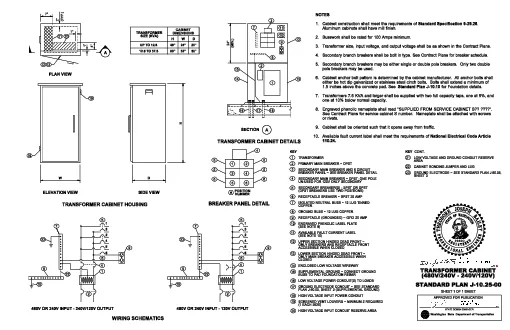
Washington State Department of TransportationSTATE DESIGN ENGINEERSHEET 1 OF 1 SHEET480V240V 240V120VTRANSFORMER CABINETSTANDARD PLAN J10250072TYP14121201213APLAN VIEWWDH1919SIDE VIEWELEVATION V ID: 876492

breaker cabinet ground voltage cabinet breaker voltage ground breakers transformer secondary input standard 240v plan conduit sheet main 120v

Share:

Link:

Embed:

Download Presentation from below link

Download Pdf The PPT/PDF document "APPROVED FOR PUBLICATION" is the property of its rightful owner. Permission is granted to download and print the materials on this web site for personal, non-commercial use only, and to display it on your personal computer provided you do not modify the materials and that you retain all copyright notices contained in the materials. By downloading content from our website, you accept the terms of this agreement.


Presentation Transcript

1 APPROVED FOR PUBLICATION Washington Stat
APPROVED FOR PUBLICATION Washington State Department of Transportation STATE DESIGN ENGINEER SHEET 1 OF 1 SHEET (480V/240V - 240V/120V) TRANSFORMER CABINET STANDARD PLAN J-10.25-00 7" 2" (TYP.) 1" 4" 1" 21 20 12 13 A PLAN VIEW W D H 19 19 SIDE VIEW ELEVATION VIEW TRANSFORMER CABINET HOUSING SIZE (KVA) TRANSFORMER H W D 48" 24" 20" 60" 32" 30" 7 12 10 5 6 9 8 14 15 13 2 16 17 18 1 SECTION A TRANSFORMER CABINET DETAILS 6 5 4 2 3 1 6 5 4 2 3 1 15 22 8 23 7 5 6 9 1 2 480V OR 240V INPUT - 240V/120V OUTPUT WIRING SCHEMATICS 480V OR 240V INPUT - 120V OUTPUT 7 23 8 15 5 6 9 1 2 1. NOTES 2. 3. 4. 5. 6. 7. 8. 9. DIMENSIONS CABINET UP TO 12.5 1 # 3 5 6 4 5 5 5 5 2 NUMBER POSITION 12.6 TO 37.5 BREAKER PANEL DETAIL (MIN.) 24" 110.24. National Electrical Code Article Available fault current label shall meet the requirements of Cabinet shall be oriented such that it opens away from traffic. or rivets. See Contract Plans for service cabinet S number. Nameplate shall be attached with screws Engraved phenolic nameplate shall read "SUPPLIED FROM SERVICE CABINET S?? ????". one at 10% below normal capacity. Transformers 7.5 KVA and larger shall be supplied with two full capacity taps, one at 5%, and for Foundation details. Standard Plan J-10.10 1.5 inches above the concrete pad. See either be hot dip galvanized or stainless steel cinch bolts. Bolts shall extend a minimum of Cabinet anchor bolt pattern is determined by the cabinet manufacturer. All anchor bolts shall pole breakers may be used. Secondary branch breakers may be either single or double pole breakers. Only two double Secondary branch breakers shall be bolt in type. See Contract Plans for breaker schedule. Transformer size, input voltage, and output voltage shall be as shown in the Contract Plans. Busswork shall be rated for 100 Amps minimum. Aluminum cabinets shall have mill finish. . Standard Specification 9-29.25 Cabinet construction shall meet the requirements of 10. 22 3 4 1 2 3 4 5 6 7 8 9 10 11 12 13 14 15 16 17 18 19 20 21 KEY 22 23 CONT. KEY 11 4 4 HIGH VOLTAGE INPUT CONDUIT RESERVE AREA (1 EACH SIDE) SCREENED VENT LOUVERS ~ MINIMUM 2 REQUIRED HIGH VOLTAGE INPUT POWER CONDUIT PLAN J-60.05, SHEET 3 (SUPPLEMENTAL GROUND) GROUND ELECTRODE CONDUIT ~ SEE STANDARD LOW VOLTAGE POWER CONDUIT(S) TO LOADS BUSS TO PAD FOUNDATION REBAR SUPPLEMENTAL GROUND ~ CONNECT GROUND ENCLOSED LOW VOLTAGE WIREWAY CLOSED ONLY MAIN BREAKER ACCESSIBLE WHEN LOWER SECTION HINGED DEAD FRONT ~ ACCESSIBLE WHEN CLOSED ONLY BREAKERS AND RECEPTACLE FRONT UPPER SECTION HINGED DEAD FRONT ~ (SEE NOTE 10) AVAILABLE FAULT CURRENT LABEL (SEE NOTE 8) ENGRAVED PHENOLIC LABEL PLATE RECEPTACLE (GROUNDED) ~ GFCI 20 AMP GROUND BUSS ~ 12 LUG COPPER COPPER ISOLATED NEUTRAL BUSS ~ 12 LUG TINNED RECEPTACLE BREAKER ~ SPST 20 AMP (DPST BREAKERS USE TWO POSITIONS) SECONDARY BREAKER(S) - SPST OR DPST UN-USED FOR 120V ONLY SECONDARY SECONDARY MAIN BREAKER ~ DPST; ONE POLE BREAKER PANEL ~ SEE BREAKER PANEL DETAIL SECONDARY MAIN BREAKER AND 6 CIRCUIT PRIMARY MAIN BREAKER ~ DPST TRANSFORMER SHEET 3 GROUND ELECTRODE ~ SEE STANDARD PLAN J-60.05, CABINET BONDING JUMPER AND LUG AREA LOW VOLTAGE AND GROUND CONDUIT RESERVE S T A T E O F W A S H I N G T O N R E G I S T E R E D P R O F E S S I O N A L E N G I N E E R 39820 Y E L I A B H P E S O J E R O D O E H T