/
Helical   Accelerating Structure with Controllable Beam Emittance Helical   Accelerating Structure with Controllable Beam Emittance

Helical Accelerating Structure with Controllable Beam Emittance - PowerPoint Presentation

aquaticle
aquaticle . @aquaticle
Follow
346 views
Uploaded On 2020-06-15

Helical Accelerating Structure with Controllable Beam Emittance - PPT Presentation

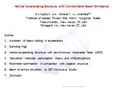
SV Kuzikov 1 AA Vikharev 1 JL Hirshfield 23 1 Institute of Applied Physics RAS Nizhny Novgorod Russia 2 Yale University New Haven CT USA 3 OmegaP Inc New Haven CT USA ID: 778123

field accelerating transverse structure accelerating field structure transverse beam hsfc electric components fields energy damping cooling focusing particles line

Share:

Link:

Embed:

Download Presentation from below link

Download The PPT/PDF document "Helical Accelerating Structure with Co..." is the property of its rightful owner. Permission is granted to download and print the materials on this web site for personal, non-commercial use only, and to display it on your personal computer provided you do not modify the materials and that you retain all copyright notices contained in the materials. By downloading content from our website, you accept the terms of this agreement.


Presentation Transcript

Slide1

Helical

Accelerating Structure with Controllable Beam Emittance

S.V. Kuzikov1, A.A. Vikharev1, J.L. Hirshfield2,31Institute of Applied Physics RAS, Nizhny Novgorod, Russia2Yale University, New Haven, CT, USA3Omega-P, Inc., New Haven, CT, USA

Outline

:

A problem of beam cooling in accelerators

Damping rings

Helical accelerating structure with asynchronous transverse fields (HSFC)

Calculation methods: perturbation theory and HFSS simulations

Parameter optimization in comparison

with

classical structure

Beam dynamics simulation by CST Microwave Studio

Conclusion

Slide2

0.3 Т

eV ILC collider

Movement of particles in a focusing channel with dry friction

Transverse

emittances

:

Particles, moving in DC-magnet undulator,

produce synchrotron radiation which leads to cooling

According to

Liouville’s

theorem the phase volume can be reduced, if only there are friction forces in a system.

Wakefields

cause growth of transverse

emittances

in accelerator behind damping rings.

Slide3

Low energy beams might be cooled in a damping ring:

Parameters:

W=5

GeV

,

I=400

mA

, P=6700

m

total

length of circumference,

T=25 ms – transverse damping time.

ILC damping ring

In case of high energy particles the damping ring becomes too long.

Slide4

Such accelerating structure is

impractical, because DC magnet system conflicts with feeding, focusing, and diagnostic systems. Inevitably large period does not allow to reach small emittance, because the smallest achievable emittance is proportional to squared wiggler period

L. The accelerator with alternating accelerating sections and wigglers reduces effective gradient.

-

cooling rate in a periodic DC-magnet field.

H.H. Braun et al. Potential of Non-standard Emittance Damping Schemes for Linear Colliders, 2004.

, where

W

– particle energy.

Slide5

Helical Self Focusing and Cooling (HSFC) Accelerating

Structure Appealing features:

1. Non-synchronous transverse field components might provide: 1) emittance control (beam cooling due to synchrotron radiation of particles); 2) near axis beam focusing2. A new structure has smooth shape of constant circular cross-section (no expansions or narrowings) and big aperture (no small irises)3. A new technology of the mass production seems possible which allows avoiding junctions inside long accelerating section

E

– accelerating field (synchronous with particles)

transverse field components

(far from Cherenkov synchronism)

Copper mandrel

HSFC = Accelerating structure + RF

undulator

+ lens

Slide6

Dispersion curves:

R

=6.09 mm, P=8 mm, a=1.25 mmPartial waves: 1) travelling TM01 mode + 2) near to cut off rotating TM

11

mode

TM

01

: E

z

0 at axis,

TM

11

:

E

z

=0 at axis, E

and H

0 at axis,

Normal waves

Partial waves

Slow normal wave 2 (

v

gr

v

ph

>0

) consists of partial TM

01

and TM

11

waves.

The wave 2 is the operating wave (might be in synchronism, it has low group velocity).

V

ph

c

V

ph

0

Slide7

Electric field in HSFC accelerating structure. Calculation by HFSS.

Slide8

Complex amplitude of the electric field

Beam line

Slide9

Accelerating field component vs

longitudinal coordinate for different phases (with step 5) Accelerating component is uniform at beam line.

Slide10

Transverse electric field components at beam line vs length for different phases

Transverse components are also uniform and have much longer spatial period in comparison with period of the accelerating component.

Slide11

Phases of electric field components at beam line

Phase of accelerating component

Phases of transverse components

Accelerating E-field and transverse E-fields have opposite phase velocities!

Phase velocity of the accelerating component actually equals the light velocity.

Slide12

Transverse components of magnetic field at beam line

In HSFC structure both transverse electric and magnetic fields cause particle’s wiggling like in RF undulator.

Slide13

Phases of magnetic field components

Transverse magnetic fields together with transverse electric fields go toward electrons.

Slide14

Simulation of electric field evolution at beam line vs length (phase step is 20

)accelerating fieldtransverse fields

Slide15

Surface electric field

Surface magnetic field

Optimization requires maximum of accelerating field normalized on maximum of surface field: Also maximum of shunt impedance is necessary:

Here holes and/or absorbers could be inserted to improve mode selection

Slide16

R

=6.09 mma=1.25 mmP=8 mmhP=4.727

f=28.2 GHzQ=10800Eacc/Esurf=0.307Rsh/L=18.9 MOhm/mResults of HFSS optimization

Example

:

f= 30 GHz structure,

G

=

E

acc

=100 MV/m, then B=0.75 T,

Beam energy W=25

GeV (=49000),then necessary decay distance

 2800 m.

Dispersion curve

Slide17

taper

Transverse particle momentums

Simulation of particle motion in 100 MV/m HSFC accelerating structure by CST Microwave Studio

Total length =10 periods

regular part

taper

TM

01

Normal wave

taper

regular part

Slide18

Parameters of cooling in 100 MV/m HSFC structure

Slide19

In HSFC structure there is gradient of the asynchronous fields which leads to appearance of the

ponderomotive

(Miller’s) force:Complex amplitude of electric fieldat different cross-sections

The

pondermotive

force (due to longitudinal TM

11

fields) in each cross-section is directed to the axis and provides beam focusing.

- frequency which electrons see.

Slide20

Bunch population during acceleration.

The blue color (at input) corresponds to low particle energy.

The red color (at output of structure) means the higher energy of the accelerated particles.Simulation of ponderomotive force focusing in HSFC accelerating structure by CST Microwave Studiobunch

Parameters: initial energy 10

GeV

, bunch length 1

ps

, bunch diameter 3 mm, charge 100

nC

, gradient 100 MV/m.

Slide21

Conclusion

TM01 – TM11 HSFC accelerating structure has non-synchronous electric and magnetic field components to be used in order to preserve low beam emittance and small energy spread.

Smooth beam focusing due to the pondermotive (Miller’s) force might also be used.The structure allows high enough accelerating gradient normalized on maximum surface field (>0.3).Shunt impedance is slightly less than in conventional accelerating structures. In order to increase shunt impedance, one might either to go to higher frequencies (Rsh/L~3/2

) or to go to lower frequencies and to apply superconductivity .