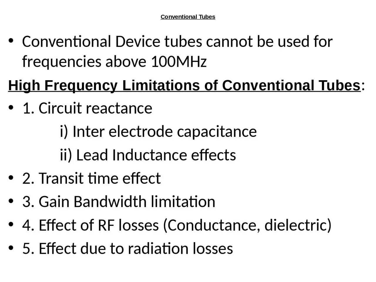
/
Conventional Tubes Conventional Device tubes cannot be used for frequencies above 100MHz Conventional Tubes Conventional Device tubes cannot be used for frequencies above 100MHz

Conventional Tubes Conventional Device tubes cannot be used for frequencies above 100MHz - PowerPoint Presentation

ava
ava . @ava
Follow
69 views
Uploaded On 2023-10-26

Conventional Tubes Conventional Device tubes cannot be used for frequencies above 100MHz - PPT Presentation

High Frequency Limitations of Conventional Tubes 1 Circuit reactance i Inter electrode capacitance ii Lead Inductance effects 2 Transit time effect 3 Gain Bandwidth limitation ID: 1024924

electron cavity reflex klystron cavity electron klystron reflex microwave beam power ghz tubes wave diode electrons tube velocity anode

Share:

Link:

Embed:

Download Presentation from below link

Download Presentation The PPT/PDF document "Conventional Tubes Conventional Device t..." is the property of its rightful owner. Permission is granted to download and print the materials on this web site for personal, non-commercial use only, and to display it on your personal computer provided you do not modify the materials and that you retain all copyright notices contained in the materials. By downloading content from our website, you accept the terms of this agreement.


Presentation Transcript

1. Conventional TubesConventional Device tubes cannot be used for frequencies above 100MHz High Frequency Limitations of Conventional Tubes:1. Circuit reactance i) Inter electrode capacitance ii) Lead Inductance effects2. Transit time effect3. Gain Bandwidth limitation4. Effect of RF losses (Conductance, dielectric)5. Effect due to radiation losses

2. Generation and amplification of Microwaves, there is a need of some special tubes called as Microwave tubes. Of them all, Klystron is an important one.Two groups of microwave devices i) Semiconductor devices Ex: Gunn Diode, Impatt diode, Schottky diode, Tunnel diode, Varacter diode, Transistors, IC’s. ii) Tube devices Ex: Klystron, Reflex Klystron,TWT,BWOEfficient Microwave tubes usually operate on the theory of electron velocity modulation concept.The electron transit time is used in the conversion of dc power to RF power.There are two basic configurations of klystron tubes 1. Reflex Klystron used as a low-power Microwave oscillator. 2. Two/Multi cavity klystron used as low-power microwave amplifier.

3.

4. KLYSTRONS The essential elements of Klystron are electron beams and cavity resonators. Electron beams are produced from a source and the cavity klystrons are employed to amplify the signals. A collector is present at the end to collect the electrons.

5. Velocity ModulationElectric field from microwaves at buncher alternately speeds and slows electron beamThis causes electrons to bunch upElectron bunches at catcher induce microwaves with more energy The cavities form a slow-wave structure

6.

7. PrincipleVelocity modulated tubeHigh velocity electron beam is generated by an electron gun and sent down along a gas tube through an input cavity (BUNCHER), drift space (FIELD FREE) and an output cavity (CATCHER) to a collector electrode anode.The anode is kept positive to receive the electrons, while the output is taken from the tube via resonant cavities with the aid of coupling loops.Two grids of the buncher cavity are separated by a small gap A while the two grids of the catcher cavity are separated by a small gap B.

8. OPERATIONThe input buncher cavity is exited by the RF signal, (the signal to be amplified) which will produce an alternating voltage of signal frequency across the gap A.This voltage generated at the gap A is responsible to produce bunching of electrons or velocity modulation of the electron beam.

9. Applegate Diagram

10. CHARACTERISTICSFrequency : 250 MHz to 100 GHzPower: 10 Kw-500 Kw (CW) 30 Mw (pulsed)Power Gain: 15 dB – 70 dB (60 dB normal)Bandwidth: limitedNoise figure: 15 – 20 dBEfficiency: 58%

11.

12. Multicavity Klystron

13. REFLEX KLYSTRON

14.

15.

16.

17. REFLEX KLYSTRONSingle Re-entrant cavity as a resonator.The electron beam emitted from the cathode is accelerated by the grid and passes through the cavity anode to the repeller space between the cavity anode and the repeller electrode .The feedback required to maintain the oscillations within the cavity is obtained by reversing electron beam emitted from the cathode towards repeller electrode and sending it back through the cavity.The electrons in the beam are velocity modulated before the beam passes through the cavity the second time and give up the energy to the cavity to maintain oscillations.This type of a Klystron is called a Reflex Klystron because of the reflex action of the electron beam.

18. CHARACTERISTICSFrequency : 4 GHz to 200 GHzPower: 1mw to 2.5 w Theoritical Efficiency: 22.78% Practical Efficiency: 10% to 20%Tuning Range: 5 GHz to 30 GHz

19.

20. REFLEX KLYSTRON

21. TRAVELLING WAVE TUBE (TWT)Traveling Wave Tube (TWT) is the most versatile microwave RF power amplifiers.The main virtue of the TWT is its extremely wide band width of operation.TWT’s are broadband devices in which there are no cavity resonators.

22.

23.

24.

25.

26.

27.

28.

29.

30.

31. BACK WARD WAVE OSCILLATOR (BWO)

32.

33.

34.

35. CHARACTERISTICS OF BWOFrequency Range: 1 GHz to 1000 GHzPower Output: 10 mw to 150 mw (CW) 20 W (at high frequencies) 250 kw (pulsed)Tuning Range: upto about 40 GHz

36. APPLICATIONS OF BWO Signal sources in instruments and transmittersBroad band noise sources (for enemy radar confusion) A noiseless oscillator with good bandwidth in the frequency range 3-9 GHz.

37.

38.

39.

40.

41.

42.

43. Voltage tunable magnetrons are used in sweep oscillators in telemetry and in missile applications Fixed frequency, CW (continuous wave) magnetrons are used for industrial heating and microwave ovens