/
Combining nadir and oblique imagery to address distortion in Combining nadir and oblique imagery to address distortion in

Combining nadir and oblique imagery to address distortion in - PowerPoint Presentation

blanko
blanko . @blanko
Follow
67 views
Uploaded On 2023-07-21

Combining nadir and oblique imagery to address distortion in - PPT Presentation

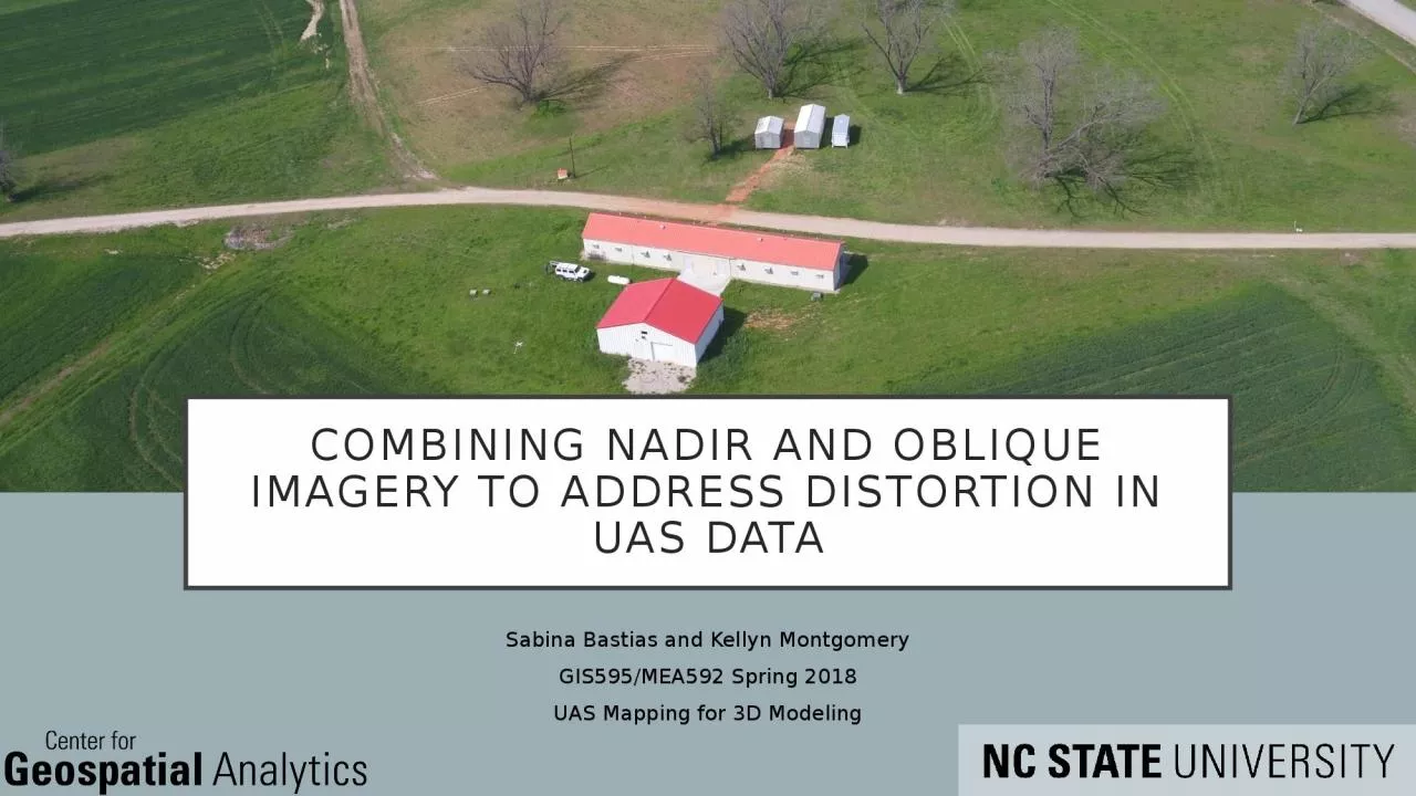
uas data Sabina Bastias and Kellyn Montgomery GIS595MEA592 Spring 2018 UAS Mapping for 3D Modeling Background Radial distortion Mitigated through software correction Browns distortion model ID: 1009596

nadir oblique imagery gcps oblique nadir gcps imagery septic dsm image vertical wheeler flight features feature buildings field vegetation

Share:

Link:

Embed:

Download Presentation from below link

Download Presentation The PPT/PDF document "Combining nadir and oblique imagery to a..." is the property of its rightful owner. Permission is granted to download and print the materials on this web site for personal, non-commercial use only, and to display it on your personal computer provided you do not modify the materials and that you retain all copyright notices contained in the materials. By downloading content from our website, you accept the terms of this agreement.


Presentation Transcript

1. Combining nadir and oblique imagery to address distortion in uas dataSabina Bastias and Kellyn MontgomeryGIS595/MEA592 Spring 2018UAS Mapping for 3D Modeling

2. BackgroundRadial distortionMitigated through software correction (Brown’s distortion model)Ground control points (GCPs)Even with GCPs, some issues remain (e.g., persistent doming, tilt along linearly placed GCPs)Surveys without GCPs? (e.g., emergency response, hazardous or inaccessible terrain)Feature ReconstructionHow to reconstruct accurate and detailed vertical object structure?Buildings (e.g., damage assessment post disaster event)Trees and other vegetation (e.g., crop growth and health, detect die back from pest damage)Literature suggests using oblique imagery (James & Robson, 2014)(James & Robson, 2014)http://www.uni-koeln.de/~al001/radcor_files/hs100.htmBackgroundProblemMethodsResultsDiscussionConclusion

3. Research ObjectivesIn cases with no GCPs, how does just nadir DSM differ from nadir + oblique DSM?How is the quality of information changed for feature reconstruction by adding oblique imagery?BackgroundProblemMethodsResultsDiscussionConclusion

4. Brantley septic siteAvailability of imagery – Rob Austin (Dept. of Soil Science, NCSU)North RaleighNewly constructed home siteInteresting featuresForest, septic field, intricate architectureLake Wheeler Field LabBrantley septic siteStudy sitesNCSU Lake Wheeler Road Field LabUAS time series 2015 - presentKnown, accurate GCPsMix of vertical featuresBuildings, trees, planted cropsBackgroundProblemMethodsResultsDiscussionConclusion

5. Data acquisitionBrantley Septic SiteData provided by Rob AustinUAS used: DJI Phantom 4 proFlight Planning Software: Pix4D CaptureCamera: 20MP 64m altitude1.56cm ground sampling distance (GSD)Image Source: DJIBackgroundProblemMethodsResultsDiscussionConclusion

6. Nadir“Lawnmower” Oblique80 degree angleBrantley Septic flight PlanBackgroundProblemMethodsResultsDiscussionConclusion

7. Data acquisitionLake Wheeler SiteDJI Phantom 3 pro Flight Planning Software: Pix4D CaptureCamera: 12.7 MP52m flight altitude 2 cm GSDImage Source: CNetBackgroundProblemMethodsResultsDiscussionConclusionImage Source: Black Hawk Aeronautical Solutions

8. Point of Interest (POI) Oblique 80 degree angleNadirLake Wheeler Flight PlanBackgroundProblemMethodsResultsDiscussionConclusion

9. Analysis / modeling methodsSoftware: Agisoft & GRASS GISGeoreferencing imagesDifference maps with custom color tablesWithout GCPs, relative DSM comparisonElevation profile analysisBackgroundProblemMethodsResultsDiscussionConclusion

10. In cases with no GCPs, how does just nadir DSM differ from nadir+oblique DSM?

11. Nadir+oblique without gcps: Brantley septic siteBrantley difference map (nadir – nadir+oblique)Adding oblique produced very different resultMajority of vegetation not captured in just nadir imageryOblique caused shift to higher elevationDifficult to determine mitigation of bowl effectSite cleared and excavated in 2017, will use lidar along road to analyze furtherNadirNadir+ObliqueBackgroundProblemMethodsResultsDiscussionConclusion

12. Nadir+oblique without gcps: MidpinesAdding oblique produced a slightly different resultClear doming occurring with just nadir imageryOblique caused shift to lower elevationBackgroundProblemMethodsResultsDiscussionConclusionMidpines difference map (nadir – nadir+oblique)

13. How is the quality of information changed for feature reconstruction(buildings and trees) by adding oblique imagery?

14. Impact on vertical features – vegetation (no gcps)Dense tree canopy not represented well in just nadirLower canopy height and densityBackgroundProblemMethodsResultsDiscussionConclusion

15. Impact on vertical features – buildings (no gcps)Oblique appears to smooth building features in Lake Wheeler datasetSome detail lost using oblique in Brantley datasetBackgroundProblemMethodsResultsDiscussionConclusion

16. DiscussionOblique imagery creates more complex DSMsPros and cons to incorporationFuture workImpact of oblique angle given size of area and flight styleOptimal number of photos used Image processing specificationsBackgroundProblemMethodsResultsDiscussionConclusion

17. Preliminary ConclusionsBoth POI and “lawn mower” techniques for oblique image acquisition are effectiveCombining nadir and oblique imagery for DSM computation does mitigate the “bowl effect” for cases without GCPsAdding oblique imagery (without GCPs) both increased and reduced detail/quality of information for vertical features.The severity of feature distortion varied between sites. Comparison of all DSMsBackgroundProblemMethodsResultsDiscussionConclusion

18. Thank youQuestions?

19. Image Processing ParametersChart explaining the overall images processed in Agisoft used in analysis. More detailed workflow followed for image processing.