/
INTERNAL COMBUSTION ENGINES INTERNAL COMBUSTION ENGINES

INTERNAL COMBUSTION ENGINES - PowerPoint Presentation

briana-ranney
briana-ranney . @briana-ranney
Follow
347 views
Uploaded On 2019-11-27

INTERNAL COMBUSTION ENGINES - PPT Presentation

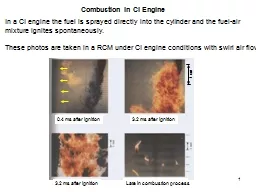
INTERNAL COMBUSTION ENGINES 1 Performance parameters Engine performance is an indication of the degree of success with which it does its assigned job ie conversion of chemical energy contained in the fuel into the useful mechanical work ID: 768264

fuel engine power brake engine fuel brake power air water pressure stroke heat cylinder 000 speed effective efficiency load

Share:

Link:

Embed:

Download Presentation from below link

Download Presentation The PPT/PDF document "INTERNAL COMBUSTION ENGINES" is the property of its rightful owner. Permission is granted to download and print the materials on this web site for personal, non-commercial use only, and to display it on your personal computer provided you do not modify the materials and that you retain all copyright notices contained in the materials. By downloading content from our website, you accept the terms of this agreement.


Presentation Transcript

INTERNAL COMBUSTION ENGINES 1

Performance parameters: Engine performance is an indication of the degree of success with which it does its assigned job i.e. conversion of chemical energy contained in the fuel into the useful mechanical work. In evaluation of engine performance certain basic parameters are chosen and the effects of various operating conditions, design concepts and modifications on these parameters are studied. 2

The basic performance parameters are numerated and discussed below:1. Power and mechanical efficiency2. Mean effective pressure and torque 3. Specific output 4. Volumetric efficiency5. Fuel-Air ratio6. Specific fuel consumption7. Thermal efficiency and heat balance8. Exhaust smoke and other emissions9. Specific weight  3

1. Power and mechanical efficiency: Indicated power. The total power developed by combustion of fuel in the combustion chamber is called indicated power. Where, k = Number of cylinders, Pmi = Indicated mean effective pressure in Pa or N/m2, L = Length of stroke in m, A = Area of piston, m2, and n = number of explosions per minute = N/2 for 4-stroke engine, = N for 2-stroke engine, N = speed of the engine on rpm. 4

(ii) Brake power (B.P.). The power developed by an engine at the output shaft is called the brake power. Where, T = torque in N-m. The difference between I.P. and B.P. is called frictional power F.P. The ratio of B.P. to I.P. is called mechanical efficiency i.e. mechanical efficiency, 5

2. Mean effective pressure and torque: Mean effective pressure is defined as hypothetical pressure which is thought to be acting on the piston throughout the power stroke. If it is based on I.P. it is called indicated mean effective pressure (Im.e.p. or P mi ) and if based on B.P. is called brake mean effective pressure (Bm.e.p. or Pmb). Similarly frictional mean effective pressure (Fm.e.p. or Pmf) can be defined as: Since the power (P) of an engine is dependent on its size and speed, therefore it is not possible to compare engine on the basis of either power or torque. Mean effective pressure is the true indication of the relative performance of different engines.  6

3 . Specific output: It is defined as the brake output per unit of piston displacement and is given by: 4. Volumetric efficiency: It is defined as the ratio of actual volume of the charge drawn in, during the suction stroke to the swept volume of the piston. The average value of this efficiency is from 70 to 80% but in case of supercharged engine it may be more than 100%, if air at about atmospheric pressure is forced into the cylinder at a pressure greater than that of air surrounding the engine. 7

5 . Fuel-Air ratio: It is the ratio of the mass of the fuel to the mass of the air in the fuel-air mixture. Relative fuel-air ratio is defined as the ratio of the actual fuel-air ratio to that of stoichiometric fuel-air ratio required to burn the fuel supplied. 6 . Specific fuel consumption: It is the mass of fuel consumed per kW developed per hour, and is a criterion of economical power production.8

7. Thermal efficiency and heat balance: Thermal efficiency is the ratio of indicated work done to energy supplied by the fuel. mf = mass of fuel supplied in kg/hr and C.V. = lower caloric value of fuel, Then indicated thermal efficiency based I.P., And brake thermal efficiency based on B.P., Where B.P and I.P are in kW 9

Heat balance sheet: The performance of an engine is generally given by heat balance sheet. To draw the heat balance sheet for I.C. engine, it should run at constant load till it attains steady state and the following readings are noted. Indicated mean effective pressure is calculated from an indicator diagram drawn with the help of an engine indicator. The quantity of the fuel used in given time and its calorific value, the amount, inlet and outlet temperature of cooling water and atmospheric and exhaust gas temperature are recorded.10

After calculating I.P. and B.P. the heat in different items is found as follows: Heat supplied by the fuel: (For petrol and oil engines) 11 Where , For gas engines, Where ,

b)Heat absorbed in B.P .  c)Heat taken away by cooling water Where, mw = mass of cooling water used in kg/s or kg/min or kg/hr, t1 = Inlet temperature of cooling water t2 = outlet temperature of cooling water C pw = Specific heat of water. 12

d)Heat taken away by exhaust gases Where, me = mass of exhaust gases in kg/s or kg/min or kg/hr, = ma + mf tr = room temperature, te = temperature of exhaust gases, Cpg = mean specific heat of exhaust gas at constant pressure, ma = mass of air supplied in kg/s or kg/min or kg/hr. 13

The heat balance sheet from the above data can be drawn as follows: 14 Particulars kJ/s or kJ/min or kJ/hr Percent a) Heat supplied by fuel ---- ------ b) Heat absorbed in B.P. c) Heat taken away by cooling water d) Heat carried away by the exhaust gases e) Heat unaccounted for (a-(b+c+d)) ---- ---- ---- ---- ------ ------ ------ ------ Total ---- ------

8. Exhaust smoke and other emissions: Smoke is an indication of incomplete combustion. It limits the output of an engine if air pollution control is the consideration. Exhaust emissions have of late become a matter of grave concern and with the enforcement of legislation of air pollution in many countries; it has become necessary to view them as performance parameters.9. Specific weight: It is defined as the weight of the engine in kg for each B.P. developed. It is an indication of the engine bulk.     15

Basic measurements: 1 . Measurement of air consumption by Air-box method: Fig shows the arrangement of the system. It consists of air-tight chamber fitted with a sharp edged orifice of known coefficient of discharge. The orifice is located away from the suction connection to the engine. Due to the suction of engine, there is a pressure of depression in the air box or chamber which causes the flow through orifice. 16

For obtaining a steady flow, the volume of chamber should be sufficiently large compared with the swept volume of the cylinder; generally 500 to 600 times the swept volume. It is assumed that the intermittent suction of the engine will not affect the air pressure in the air box as volume of the box is sufficiently large, and pressure in the box remains same. A water manometer is used to measure the pressure difference causing the flow through the orifice. The depression across the orifice should not exceed 100 to 500mm of water. 17

Let A = Area of the orifice in m 2, d = Diameter of the orifice, m, hw = Head of water in m, Cd = Coefficient of discharge for orifice, ρa = Density of air in kg/m3 under atmospheric conditions, and ρw = Density of water in kg/m3 = 1000kg/m3.Head in meters of air is given by: The velocity of air passing through the orifice is given by, The volume of air passing through the orifice,   Mass of air passing through the orifice is given by 18

2. Measurement of Brake Power i ) By rope brake dynamometer:  The arrangement for determination of B.P. of the engine is known as dynamometer. In rope brake dynamometer a rope is wound round the circumference of the brake wheel (Fig). To one end of the rope is attached a spring balance (S) and the other end carries the load (W). The speed of the engine is noted from the tachometer. 19

If, W = Weight at the end of the rope, in N, S = Spring balance reading, in N, N = Engine speed, in r.p.m., Db = Diameter of the brake wheel, in m, dr = diameter of the rope, in m, and (D b + dr) = Effective diameter of the brake wheel,  Then work/revolution = Torque X angle turned per revolution20 Where,

21 Therefore, By prony brake dynamometer: This arrangement consists of a pair of brake shoes (usually made of wood) which are held in place by means of spring loaded bolts. The pressure on the rim of the brake drum (wheel) is adjusted with the help of the nuts. Weights are placed on the load carrier at the end of the load bar (lever). Increasing the weights will increase the pressure of the brake shoes on the drum, which results in an increase in the frictional torque that the engine has to overcome.

If W = weight of the load carrier L = distance between shaft axis and the line of action of weight. Frictional torque to be overcome = T = W.LTherefore the brake power of the engine, 22 Where, W, load in Newton and L in metre.

3. Measurement of Indicated Power: i ) By using Engine Indicator: Indicator power is usually determined with the help of a p-V diagram taken with the help of a engine indicator. The indicated power may be computed by measuring the area of the diagram, either with a planimeter or by ordinate method, and dividing by the stroke measurement in order to obtain the mean effective pressure ( m.e.p .).  23

i.e., 24 Where, P mi in bar or kPa or Pa if ‘s’ is in bar/mm or kPa/mm or Pa/mm respectively. Calculation of indicated power: If, Pmi = Indicated mean effective pressure in Pa, A = Area of piston, m 2 , L = Length of stroke in, m, n = Number of explosions per min, or Number of working strokes per min, = N, for 2-stroke engine, and = N/2, for 4-stroke engine, N = Speed of the engine, rpm, and k = Number of cylinders.

25 i.e., i.e., indicted power, If ‘k’ is the number of cylinders,

ii) By Morse Test: This test is applicable only to multi-cylinder engines. The engine is run at the required speed and the torque is measured. One cylinder is cut-off by shorting the plug if an S.I. engine is under test, or by disconnecting an injector if a C.I. engine is under test. The speed falls because of the loss of power with one cylinder cut-off, but is restored by reducing the load. The torque is measured again when the speed has reached its original value. 26

If the values of the I.P. of the cylinders are denoted by (considering 4-cylinder engine), and the power losses in each cylinder are denoted by then the value of B.P., B at the test speed with all cylinders firing is given by, If number 1 cylinder is cut-off, then the contribution I1 is lost: and if the losses due to that cylinder remain the same as when it is firing, then the B.P., B1, now obtained at the same speed is 27 Subtracting equation (2) from (1), we get Similarly, Then for the engine,

4. Measurement of Frictional Power: i ) Willan’s line method: At a constant engine speed the load is reduced in increments and the corresponding B.P. and gross fuel consumption are taken. A graph is then drawn of fuel consumption against B.P. as in Fig. The graph drawn is called Willan’s line and is extrapolated back to cut the B.P. axis at the point L. The reading OL is taken as the power loss of the engine at that speed. The fuel consumption at zero B.P. is given by OM; and if the relationship between fuel consumption and B.P. is assumed to be linear, then a fuel consumption OM is equivalent to a power loss of OL.28

This method is used only in case of unthrottled engines as discussed below: The Willan’s line is plotted for fuel consumption versus load at constant speed. The intersection of this line on the negative side of X-axis gives the Friction Power of the engine at that speed. The friction power (F.P.) is assumed constant from no load to full load at that constant speed. The F.P. includes not only the mechanical friction, but also the pumping power.    29

For a throttled engine if such a test is carried out, the throttle position has to be varied from almost closed at no load to full open at maximum load, to keep the engine speed constant. Therefore the pumping load will be bigger at no load, and reduce gradually as the load is increased. In other words, the pumping power and therefore the F.P. will not remain constant, as the assumption in Willan’s line method.   30

ii) By Morse test: In Morse test (already discussed), the frictional power can be found by subtracting Therefore, Where ‘n’ is the number of cylinders.  31

iii) Motoring test: In this test the engine is first run up to the desired speed by its own power and allowed to remain under the given speed and load conditions for some time so that oil, water and engine component temperature reach stable conditions. The power of the engine during this period is absorbed by a dynamometer. 32

The fuel supply is then cut-off and by suitable electric switching devices the dynamometer is converted to run as motor to drive or ‘motor’ the engine at the same speed at which it was previously running. The power supply to the motor is measured which is a measure of F.P. of the engine. Motoring test gives a very good insight into the various causes of losses and is much more powerful tool. This test gives a higher value of F.P. as compared to that given by Willan’s line method. 33

5. Measurement of fuel consumption: The mass rate of fuel consumption is measured by noting the time taken for the consumption of a known volume of fuel. If V cc of fuel is consumed in ‘t’ seconds, then mass rate of fuel consumption is 34

6. Measurement of Heat carried away by cooling water: The heat carried away by cooling water is measured by measuring the water flow rate through the cooling jacket and rise in temperature of the water during its flow through the engine block. The inlet and exit temperatures of cooling water are measured by thermometers inserted in the wells provided. The flow rate of water is measured by collecting the water in the bucket over a specified period and by weighing the water collected. The water flow rate can also be measured by using a rotameter or flow meter. The heat carried away by cooling water is given by  Where, mw = mass flow rate of water in kg/sec, Cpw = specific heat of water in kJ/kg-K, t1 and t2 = inlet and outlet temperature of water. 35

7. Measurement of heat carried away by exhaust gases: The mass of the exhaust gases is equal to the sum of the masses of air and fuel. Mass flow rate of exhaust gas is given by, ma = mass flow rate of water m f = mass flow rate of fuel therefore heat carried away by exhaust gases is given by Where, Cpe = specific heat of exhaust gases in kJ/kg-K t e = temperature of exhaust gases. t r = ambient temperature. 36

Prob 1:- The following observations have been made from the test of a four cylinder, two – stroke petrol engine. Diameter of the cylinder = 10 cm; stroke = 15 cm; speed = 1600 rpm; Area of indicator diagram = 5.5 cm2; Length of the indicator diagram = 55 mm; spring constant = 3.5 bar/cm; Determine the indicated power of the engine.Given:- d = 0.1 m; L = 0.15 m ; No. of cylinders = K = 4; N = 1600 rpm; n = N (two – stroke); A = 5.5 cm 2 ; length of the diagram = ld = 5.5. cm; spring constant = ks = 3.5 bar/cm ;37

To find: indicated power, ip .  A ksSolution: Indicated mean effective pressure = pim = ------------ l d  5.5 x 3.5or pim = -------------- = 3.5 bar = 3.5 x 10 5 N / m2 5.5  p im LAnK 3.5 x 105 x 0.15 x ( π/4) x 0.12 x 1600 x 4Indicated power = IP = ---------------- = ------------------------------------------- 60,000 60,000  = 43.98 kW 38

2). A gasoline engine (petrol engine) working on Otto cycle consumes 8 liters of petrol per hour and develops 25 kW. The specific gravity of petrol is 0.75 and its calorific value is 44,000 kJ/kg. Determine the indicated thermal efficiency of the engine. Given:- Volume of fuel consumed/hour = Vs/t = 8 x 10 3 / 3600 cc/s ; IP = 25 kW; C.V = 44,000 kJ/kg; Specific gravity of petrol = s = 0.75 39

To find: η ith ; V X S 8 x 10 3 x 0.75Solution: Mass of fuel consumed = m f = ----- = ------------------ 1000 t 1000 x 3600  = 1.67 x 10 − 3 kg/s. IP 25Indicated thermal efficiency = η ith = --------- = --------------------------- m f C.V 1.67 x 10 − 3 x 44000  = 0.3402 = 34.02 %.  40

3) The bore and stroke of a water cooled, vertical, single-cylinder, four stroke diesel engine are 80 mm and 110 mm respectively. The torque is 23.5 N- m. Calculate the brake mean effective pressure. What would be the mean effective pressure and torque if the engine rating is 4 kW at 1500 rpm?  Given:- Diameter = d = 80 x10 − 3 = 0.08 m ; stroke = L = 0.110 m; T = 23.5 N-m;   To find (i) bmep ; (ii) bmep if bp = 4 kW and N= 1500 rpm.41

Solution: ( i) Relation between brake power (bp) and brake mean effective pressure(bmep) is given by bp = 2πNT (bmep)LAn ------------ = --------------- 60,000 60,000   Hence bmep = (2πNT) / (LAn) = (2πNT) / {(Lxπd2 /4) N/2}  16T 16 x 23.5= ------------- = ---------------- = 5.34 x 10 5 N / m2 = 5.34 bar d 2 L 0.08 2 x 0.11 42

(ii) when bp = 4 kW and N = 1500 rpm, we have   60,000 bp 60,000 x 4bmep = -------------- = ------------------------------------------. LAn 0.110 x (π/4) x 0.08 2 x (1500 / 2)  = 5.79 x 10 5 N/m2 = 5.79 bar.  60,000 bp 60,000 x 4Also bp = 2πNT / 60,000 or T = ---------------- = -------------------- 2πN 2 x π x 1500 43 = 25.46 N – m.

4)Find the air fuel ratio of a four stroke, single cylinder, air cooled engine with fuel consumption time for 10 cc is 20.4 s and air consumption time for 0.1 m 3 is 16.3s. The load is 7 N at the speed of 3000 rpm. Find also the brake specific fuel consumption in kg/kWh and brake thermal efficiency. Assume the density of air as 1.175kg/m3 and specific gravity of the fuel to be 0.7. The lower heating value of the fuel is 43MJ/kg and the dynamometer constant is 5000. 44

Given:- V = 10 cc ; t = 20.4 s ; Va = 0.1 m3; ta = 16.3 s ; W = 7 N ; N = 3000 rpm;  ρ a = 1.175 kg/m3; s = 0.7 ; CV = 43 x 103 kJ/kg; Dynamometer constant = C = 5000.To find:- (i) ma / mf ; (ii) bsfc ; (iii) η bth . 0.1 x 1.175 Solution: (i) Mass of air consumed = ma = ---------------- 16.3 = 7.21 x 10 − 3 kg/s. V X S 10 x 0.7 Mass of fuel consumed = m f = --------- = ------------------ 1000 t 1000 x 20.4 = 0.343 x 10 − 3 kg/s 45

Air fuel ratio = m a= 7.21 x 10− 3 = 21 mf 0.343 x 10 − 3 7 x 3000(ii) Brake power = bp = WN / C = ------------- = 4.2 kW 5000 mf x 3600 0.343 x 10 −3 x 3600bsfc = --------------- = ---------------------------- = 0.294 kg/kWh bp 4.2 bp 4.2(iii) bith = --------------- = ----------------------------------- = 0.2848 = 28.48 %. m f CV 0.343 x 10 −3 x 43 x 10 3      46

5:- A six cylinder, gasoline engine operates on the four stroke cycle. The bore of each cylinder is 80 mm and the stroke is 100 mm. The clearance volume in each cylinder is 70 cc. At a speed of 4000 rpm and the fuel consumption is 20 kg/h. The torque developed is 150 N-m. Calculate ( i) the brake power, (ii) the brake mean effective pressure, (iii) brake thermal efficiency if the calorific value of the fuel is 43000 kJ/kg and (iv) the relative efficiency if the ideal cycle for the engine is Otto cycle.   47

Given:- K = 6 ; n = N /2 ; d = 8 cm ; L = 10 cm ; Vc = 70 cc ; N = 4000 rpm ; mf = 20 kg/h ; T = 150 N-m ; CV = 43000 kJ/kg ; To find:- (i) bp ; (ii) bmep ; (iii) ηbth ; (iv) η Relative. Solution: (i) bp = 2π NT = 2 x π x 4000 x 150 60,000 60,000   = 62.8 kW   60,000 bp 60,000 x 62.8(ii) bmep = -------------------- = -------------------------------------------- L A n K 0.1 x (π / 4) x 0.08 2 x (4000/2) x 6  = 6.25 x 10 5 N/m 2 = 6.25 bar bp 62.8(iii) ηbth = ----------------------- = ------------------------------ = 0.263 = 26.3 %. mf CV (20 / 3600) x 43,000 48

(iv) Stroke volume = Vs = (π / 4) d 2 L = (π / 4) x 8 2 x 10 = 502.65 cc  Vs + Vc 502.65 + 70Compression Ratio of the engine = Rc = ------------ = ----------------- = 8.18 Vc 70 Air standard efficiency of Otto cycle = η Otto = 1 – (1/ Rc(γ – 1))  1 = 1 − -------------- = 0.568 = 56.8 % 8.18 0.4 Hence Relative efficiency = ηRelative = η bth / η Otto = 0.263 / 0.568 = 0.463 = 46.3 %. 49

6) An eight cylinder, four stroke engine of 9 cm bore, 8 cm stroke and with a compression ratio of 7 is tested at 4500 rpm on a dynamometer which has 54 cm arm. During a 10 minute test, the dynamometer scale beam reading was 42 kg and the engine consumed 4.4 kg of gasoline having a calorific value of 44,000 kJ/kg. Air at 27 C and 1bar was supplied to the carburetor at a rate of 6 kg/min. Find ( i) the brake power, (ii) the brake mean effective pressure, (iii) the brake specific fuel consumption, (iv) the brake specific air consumption, (v) volumetric efficiency , (vi) the brake thermal efficiency and (vii) the air fuel ratio.   50

Given:- K = 8 ; Four stroke hence n = N/2 ; d = 0.09 m; L = 0.08 m; Rc = 7; N = 4500rpm; Brake arm = R = 0.54 m ; t = 10 min ; Brake load = W = (42 x 9.81) N. mf = 4.4 kg ; CV = 44,000 kJ/kg ; Ta = 27 + 273 = 300 K ; pa = 1 bar; m a = 6 kg/min;To find:- (i) bp ; (ii) bmep ; (iii) bsfc ; (iv) bsac ; (v) ηv ; (vi) η bth ; (vii) ma / mf51

Solution: 2π NT 2π NWR 2 x π x 4500 x (42 x 9.81) x 0.54(i) bp = ----------- = ------------ = ------------------------------------------- 60,000 60,000 60,000  = 104.8 kW   60,000 bp 60,000 x 104.8(ii) bmep = ------------- = ------------------------------------------------ L A n K 0.08 x (π / 4) x 0.09 2 x (4500 / 2) x 8  = 6.87 x 10 5 N/m2 = 6.87 bar. 52

(iii) mass of fuel consumed per unit time = m f = mf / t = 4.4 x 60 / 10 kg/h   = 26.4 kg/h  m f 26.4Brake specific fuel consumption = bsfc = ----------- = ------------- . bp 104.8  ma 6 x 60(iv) brake specific air consumption = bsac = ---------- = --------- bp 104.8 = 3.435 kg / kWh 53

bp 104.8 (v) ηbth = ---------------- = ----------------------------- = 0.325 = 32.5 %. mf CV (26.4 / 3600) x 44,000 (vi) Stroke volume per unit time = Vs = (πd 2 /4) L n K  π = ------ x (0.092) x 0.08 x (4500 / 2) x 8 4  = 9.16 m3 / min.  m a Ra Ta 6 x 286 x 300Volume flow rate of air per minute = Va = ------------- = -------------------- p a 1 x 10 5  = 5.17 m 3 / min   Volumetric efficiency = η v = Va / Vs = 5.17 / 9.16 = 0.5644 = 56.44 %.(vii) Air fuel ratio = m a / mf = 6 /(4.4 / 10) = 13.64  54

7) A gasoline engine working on four- stroke develops a brake power of 20.9 kW. A Morse test was conducted on this engine and the brake power (kW) obtained when each cylinder was made inoperative by short circuiting the spark plug are 14.9, 14.3,14.8 and 14.5 respectively. The test was conducted at constant speed. Find the indicated power, mechanical efficiency and brake mean effective pressure when all the cylinders are firing. The bore of the engine is 75mm and the stroke is 90 mm. The engine is running at 3000 rpm. 55

Given:- brake power when all cylinders are working = Bt = 20.9 kW ;  Brake power when cylinder 1 is inoperative = B1 = 14.9 kW ; Brake power when cylinder 2 is inoperative = B2 = 14.3 kW ; Brake power when cylinder 3 is inoperative = B3 = 14.8 kW ; Brake power when cylinder 4 is inoperative = B4 = 14.5 kW ; N = 3000 rpm ; d = 0.075 m ; L = 0.09 m ; To find:- (i) (ip)total ; (ii) ηmech ; (iii) bmep ; 56

Solution: ( ip)total = ip1 + ip2 + ip3 + ip4 = (Bt – B1) + (Bt – B2) + (Bt – B3) + (Bt – B 4 )  = 4B t – (B1 + B2 + B3 + B4) = 4 x 20.9 – (14.9 + 14.3 + 14.8 + 14.5)  = 25.1 KW   B t 20.9 (ii) η mech = ------------- = --------- = 0.833 = 83.3 % (ip) total 25.1 57

60,000 B t 60,000 x 20.9(iii) bmep = --------------- = -------------------------------------------------- L A n K 0.09 x (π / 4) x 0.0752 x (3000 / 2) x 4  = 5.25 x 10 5 N / m2 = 5.25 bar.58

8) The following observations were recorded during a trail of a four –stroke, single cylinder oil engine. Duration of trial = 30 min ; oil consumed = 4 litres ; calorific value of oil = 43 MJ/kg ; specific gravity of fuel = 0.8 ; average area of the indicator diagram = 8.5 cm2; length of the indicator diagram = 8.5 cm; Indicator spring constant = 5.5 bar/cm; brake load = 150 kg; spring balance reading = 20 kg; effective brake wheel diameter = 1.5 m ; speed= 200 rpm ; cylinder diameter = 30 cm ; stroke = 45 cm ; jacket cooling water = 10 kg/min ; temperature rise of cooling water = 36 C. Calculate ( i ) indicated power, (ii) brake power, (iii) mechanical efficiency, (iv) brake specific fuel consumption, (v) indicated thermal efficiency, and (vi) heat carried away by cooling water.59

Given:- t = 30 min ; V = 4000 cc; CV = 43 x10 3 kJ/kg; s = 0.8 ; area of the diagram = a =8.5 cm2; length of the diagram = ld = 8.5 cm ; indicator spring constant = k s = 5.5 bar /cm; W = 150 x 9.81 N ; Brake radius = R = 1.5 / 2 = 0.75 m; N = 200 rpm ; d = 0.3 m ; L = 0.45 m ; mw = 10 kg/min ; ∆Tw = 36 C; Spring Balance Reading = S = 20 x 9.81 N.To find:- (i) ip ; (ii) bp ; (iii) η mech ; (iv) bsfc ; (v) ηith ; (vi) Q w   60

Solution:  a 8.5 (i) pim = ------- ks = ----------- x 5.5 = 5.5 bar = 5.5 x 10⁵ N/m2 ld 8.5 pim L A n K 5.5 x 10 5 x 0.45 x (π / 4) x 0.32 x (200 / 2) x 1ip = ------------------- = ------------------------------------------------------------ 60,000 60,000  = 29.16 kW   2π N(W – S) R 2 x π x 200 x (150 – 20)x 9.81 x 0.75 (ii) bp = ----------------------- = ------------------------------------------------ 60,000 60,000  = 20.03 kW (iii) ηmech = bp / ip = 20.03 / 29.16 = 0.687 = 68.7 %. 61

    V x S 4000 x 0.8(iv) Mass of fuel consumed per hour = mf = --------- x 60 = -------------- x 60 1000 t 1000 x 30   = 6.4 kg / h.   6.4 bsfc = mf / bp = ------------- = 0.3195 kg/kWh 20.03 ip 29.16 (v) ηith = ------------ = -------------------------------- = 0.3814 = 38.14 %. mf CV (6.4 / 3600) x 43 x 10 3  (vi) Qw = m Cp ∆Tw = (10 / 60) x 4.2 x 36 = 25.2 kW 62

9) A four stroke gas engine has a cylinder diameter of 25 cm and stroke 45 cm. The effective diameter of the brake is 1.6 m. The observations made in a test of the engine were as follows. Duration of test = 40 min; Total number of revolutions = 8080 ; Total number of explosions = 3230; Net load on the brake = 80 kg ; mean effective pressure = 5.8 bar; Volume of gas used = 7.5 m 3; Pressure of gas indicated in meter = 136 mm of water (gauge); Atmospheric temperature = 17 0 C; Calorific value of gas = 19 MJ/ m3 at NTP; Temperature rise of cooling water = 45 C; Cooling water supplied = 180 kg. Draw up a heat balance sheet and find the indicated thermal efficiency and brake thermal efficiency. Assume atmospheric pressure to be 760 mm of mercury.  63

Given:- d = 0.25 m ; L = 0.45 m; R = 1.6 / 2 =0.8 m; t = 40 min ; Ntotal = 8080 ; Hence N = 8080 / 40 = 202 rpm ntotal = 3230 ; Hence n = 3230 / 40 = 80.75 explosions / min; W = 80 x 9.81 N; p im = 5.8 bar ; Vtotal = 7.5 m3; hence V = 7.5 / 40 = 0.1875 m3/min; pgauge = 136 mm of water (gauge);  T atm = 17 + 273 = 290 K; ( CV) NTP = 19 x 10 3 kJ/ m3 ; ∆Tw = 45 C; mw = 180 / 40 = 4.5 kg/min; patm = 760 mm of mercury64

10).A test on a two-stroke engine gave the following results at full load.   Speed = 350 rpm; Net brake load = 65 kg ; mean effective pressure = 3 bar ; Fuel consumption = 4 kg/h ; Jacket cooling water flow rate = 500 kg/h ; jacket water temperature at inlet = 20 C ; jacket water temperature at outlet = 40 C ; Test room temperature = 20 C ; Temperature of exhaust gases = 400 C; Air used per kg of fuel =32 kg ; cylinder diameter = 22 cm ;stroke = 28 cm; effective brake diameter = 1 m ; Calorific value of fuel = 43 MJ/kg ; Mean specific heat of exhaust gases = 1 kJ/kg –K. Find indicated power, brake power and draw up a heat balance for the test in kW and in percentage. 65