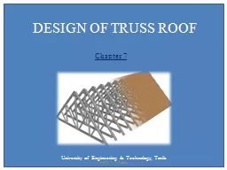
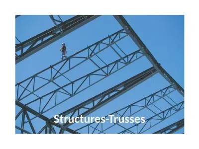
Roof Trusses Trusses are triangular frame works consisting of axially loaded members They are more efficient in resisting external loads as the cross section of all the members ID: 635757
Download Presentation The PPT/PDF document "DESIGN OF STEEL ROOF TRUSSES" is the property of its rightful owner. Permission is granted to download and print the materials on this web site for personal, non-commercial use only, and to display it on your personal computer provided you do not modify the materials and that you retain all copyright notices contained in the materials. By downloading content from our website, you accept the terms of this agreement.
Slide1
DESIGN OF STEEL ROOF TRUSSESSlide2
Roof Trusses
Trusses
are
triangular frame
works, consisting of
axially
loaded members
They
are
more efficient in resisting external loads
as the
cross
section of
all the members
are
nearly uniformly stressed
.
They
are extensively
used for
larger spans Slide3
Applications Trusses are used in
Roofs of
single storey industrial buildings
long span floors and roofs of multistory buildings
, to resist gravity loads.
Trusses are also used in
walls and horizontal planes of industrial buildings to resist lateral loads
and to provide
lateral stability
.Slide4
Analysis of Trusses
Truss members are regarded as being
pinned joints.
They
are assumed to be joined together so as to
transfer only the axial forces and not moments and shears
from one member to the adjacent members
The
loads
are assumed to be acting only at the
nodes of the trusses
. Slide5
Analysis of Trusses
The trusses may be provided over
a
single span, simply supported over the two end supports
, in which case they are usually
statically determinate
.
Such trusses can be analyzed manually by
method of joints
method of sections
.
Computer programs
are also available for the analysis of trusses.Slide6
Analysis of Trusses
From the analysis based on
pinned joint assumption
, we can get the
axial forces in the different members of the trusses are found
.
In actual design, the members of the trusses are joined together by more than one
bolt or by welding
, either
directly or through larger size end gussets
.Slide7
Analysis of Trusses
Further, some of the members, particularly
chord members
, may be
continuous over many nodes
. Generally such joints enforce not only
compatibility of translation
but also
compatibility of rotation
of members meeting at the joint.Slide8
Analysis of Trusses
As a result, the members of the trusses experience
bending moment
in addition to axial force. This may
not be negligible
, particularly at the
eaves points of pitched roof trusses,
where the
depth is small
and in trusses with members having a
smaller slenderness ratio
.Slide9
Analysis of Trusses
Further, the loads may be applied
in between the nodes of the trusses
, causing
bending of the members
. Such stresses are referred to as
secondary stresses
.
The
secondary bending stresses
can be caused also by the
eccentric connection of members at the joints.
Slide10
Methods to reduce BM in columns(Knee Bracings)Slide11
Analysis of Trusses
The
analysis
of trusses for the
secondary moments and hence the secondary stresses
can be carried out by an
indeterminate structural analysis
, usually using computer
software
.
The
magnitude
of the secondary stresses due to joint rigidity
depends upon
the
stiffness
of the
joint
and the
stiffness
of the
members
meeting at the joint. Slide12
Analysis of Trusses
Secondary stresses
in roof trusses may be
disregarded
if
Slenderness ratio of the
chord members is greater than 50
and that of the
web members is greater than 100
.
The
secondary stresses
cannot be neglected
When they are induced due to application of
loads on members in between nodes
and when the
members are joined eccentrically
.Slide13
Analysis of Trusses
Further the secondary stresses
due to the rigidity of the joints cannot be disregarded
In the case of
bridge trusses,
due to the
higher stiffness of the members
and the effect of secondary stresses on
fatigue strength of members.Slide14
Materials for RoofingSlide15
Fastenings for SheetingSlide16
Side lap Corrugated SheetSlide17
Flat Cum Corrugated SheetsSlide18
Types of Roof TrussPitched roof trusses
Parallel chord trusses
Trapezoidal trussesSlide19
Pitched Roof Trusses
Most common
types of roof trusses
Top chord
is provided with a
slope
in order to
facilitate natural drainage
of rainwater and clearance of
dust/snow accumulation
.
The typical span to maximum
depth ratios
of pitched roof trusses are in the range of
4
to 8,
the
larger ratio being economical in
longer spans.Slide20
Pitched Roof TrussesThese trusses have a
greater depth at the mid-span.
Due to this even though the
overall bending effect is larger at mid-span
, the
chord member and web member stresses are smaller closer to the mid-span
and
larger closer to the supports. Slide21
King Post TrussSlide22
Queen Post TrussSlide23Slide24
Pratt Truss (6-30m)
In Pratt trusses [Fig. (
a
)] web members are arranged in such a way that under gravity load the
longer diagonal members are under tension
and the
shorter vertical members experience compression
.
This allows for
efficient design, since the short members are under compression
.
However, the
wind uplift may cause reversal of stresses
in these members and
nullify this benefit. Slide25
Howe Truss (6-10m)
The converse of the Pratt is the Howe truss [Fig. (
b
)]. This is commonly used in light roofing so that the
longer diagonals experience tension
under
reversal of stresses due to wind load.Slide26
Fink Trusses(up to 10m)
Fink trusses [Fig. (
c
)] are used for
longer spans having high pitch roof,
The
web
members in such truss are
sub-divided to obtain shorter members
.Slide27
Fan Trusses (10-15m)
Fan trusses [Fig. (
d
)] are used when the
rafter members
of the roof trusses have to be sub-divided into
odd number of panels
. Slide28
Fink Fan Truss (20-30m)
A combination of fink and fan [Fig. (
e
)] can also be used to some advantage in some
specific situations requiring appropriate number of panels
.Slide29
Mansard Trusses(20-30m)
Mansard trusses [Fig. (
f
)] are variation of fink trusses, which have
shorter leading diagonals even in very long span trusses
, unlike the fink and fan type trusses.Slide30
Economical SpanThe
economical span
lengths of the
pitched roof trusses
, excluding the Mansard trusses, range from
6 m to 12 m
.
The
Mansard trusses
can be used in the span ranges of
12 m to 30 m
.Slide31
Parallel Chord TrussesSlide32
Parallel Chord TrussesThe parallel chord trusses are used to support
North Light roof trusses
intermediate span bridges
pre-fabricated floor joists, beams and girders in multi- storey buildings
Warren configuration is frequently usedSlide33
Parallel Chord TrussesThe advantage of parallel chord trusses is that they use
webs of the same lengths
and thus
reduce fabrication costs
for very long spans.
Modified Warren
is used
with additional verticals,
introduced in order
to reduce the unsupported length of compression
chord members.
The
saw tooth north light roofing systems
use parallel chord
lattice girders to support the north light trusses
and transfer the load to the end columns.Slide34
Parallel Chord Trusses
The economical
span to depth ratio
is in the range of
12 to 24.
The total span is subdivided into a number of panels such that the individual panel lengths are appropriate (6m to 9 m) for the stringer beams, and the
inclination of the web members
are around
45 degrees
.
In the case of
very deep trusses
it may become necessary to use
K and diamond patterns
for web members to achieve appropriate inclination of the web members. Slide35
Trapezoidal Trusses
In case of
very long span pitched roof
, trusses having trapezoidal
configuration, with depth at the ends
are used [Fig. (
a
)]. This configuration
reduces the axial forces in the chord members adjacent to the supports
.
Secondary bending
effects in these members are also
reduced.
The trapezoidal configurations [Fig. (
b
)] having the
sloping bottom chord
can be
economica
l in very long span trusses
(spans > 30 m),
since they tend to
reduce the web member length
and the chord members tend to have
nearly constant forces
over the span length. Slide36
Trapezoidal TrussesSlide37
Common types of roof trussesSlide38
Common types of roof trussesSlide39
Roof typesSlide40Slide41Slide42
Industrial buildings with different spansSlide43
Structural framing for an industrial buildingSlide44Slide45Slide46Slide47Slide48Slide49Slide50
Truss MembersSlide51
Truss members
LIGHTER LOADS :
Rolled steel angles, Tee sections, Hollow circular / rectangular structural tubes [Fig. (a)].
HEAVY LOADS :
heavier rolled steel sections, such as channels, I sections are used [Fig. (
b
)].
LONG SPAN BRIDGE TRUSSES :
Built-up sections
Members built-up using I-Sections, channels, angles and plates [Fig.
c
)]Slide52
Truss ConnectionsMembers of trusses can be joined by
Riveting,
Bolting
Welding.
Due to involved procedure and highly skilled
labour
requirement
, riveting is not common these days.
High strength friction grip (HSFG)
bolting and welding
have become more common. Slide53
Truss ConnectionsShorter span trusses
are usually
fabricated in shops
and can be completely welded and
transported to site as one unit
.
Longer span trusses
can be
prefabricated in segments
by welding in shop. These segments can be
assembled by bolting or welding at site
. Slide54
Truss Connections
Truss connections
form a
high proportion of the total truss cost
. Therefore it may not always be economical to select member sections, which are efficient but cannot be
connected economically
.
Trusses may be
single plane trusses
in which the members are
connected on the same side of the gusset plates
or
double plane trusses
in which the members are connected on
both sides of the gusset plates.Slide55
Truss Connections
It may not always be possible to design connection in which the
centroidal
axes of the member sections are coincident
Small eccentricities
may be
unavoidable
and the
gusset plates should be strong enough
to resist or transmit forces arising in such cases without buckling
The
bolts should also be designed to resist moments arising due to in-plane eccentricities
. If
out-of-plane instability
is foreseen,
use splice plates
for continuity of out-of-plane stiffness.Slide56
Truss ConnectionsSlide57
Gusset PlateThe size, shape and the thickness of the gusset plate depend upon the
size of the member being joined
,
number and size of bolt
or
length of weld
required, and the
force
to be transmitted.
The thickness of the gusset is in the range of
8 mm to 12 mm in the case of roof trusses
and it can be as high as
22 mm in the case of bridge trusses
. Slide58
Gusset PlateThe design of gussets is usually by
thumb rule
.
In short span
(8 – 12 m)
roof trusses, the member forces are smaller, hence the thickness of gussets are lesser
(6 or 8 mm)
For longer span lengths
(> 30 m)
the thickness of gussets are larger
(12 mm). Slide59
Cross Braced Lattice Wind GirderSlide60
Welded connectionsSlide61
Bolted ConnectionsSlide62
Connection of bolted lattice girderSlide63
Open web steel jointsSlide64Slide65
Three dimensional lattice girderSlide66
Purlins
Purlins
are subjected to
Bending about
major axis
due to the components of
DL, LL & WL normal to the axis of
purlin
section
Bending about
minor axis
due to the components of
DL & LL normal to the axis
of
purlin
sectionSlide67
PurlinsDesigned in accordance with the requirements of
encased beams
Designed as
continuous beams
with
laterally supported comp. flange
-connections in
sheetings
All working loads should be multiplies with suitable
partial load factors
BM
calculated by
plastic analysis
For calculation
of flexural strength, shear strength
should also be
checkedSlide68
PurlinsLimiting deflection
1/150 for elastic cladding
(GI Sheets)
1/180 for Brittle cladding
(AC Sheets)Slide69
Design of Trusses
Compression members of the trusses have to be checked for their
buckling strength about the critical axis
of the member. This buckling may be
in plane or out-of-plane
of the truss or about an
oblique axis
as in the case of
single angle sections
.
All the members of a roof truss usually do not reach their limit, members
usually have certain rigidity,
depending
on the
restraint to the members under compression
by the adjacent members and the rigidity of the joint
.
Effective length
of the member for calculating the buckling strength
may be less than the c/c length of the joints. Slide70
Design of TrussesThe design codes suggest an effective length factor between
0.7 and 1.0
for the
in-plane buckling
of the member depending upon this restraint and
1.0 for the out of plane buckling
.Slide71
Design of TrussesA member under
tension due to gravity loads
(dead and live loads) may experience
stress reversal into compression
due to
dead load and wind load combination
.
Similarly the
web members of the bridge truss
may undergo
stress reversal during the passage of the moving loads on the deck
. Such
stress reversals and instability
due to the stress reversal should be considered in design. Slide72
Economy of Trusses
Trusses consume
a lot less material compared to beams to span the same length and
transfer moderate to heavy loads
. However, the
labour
requirement
for
fabrication and erection of trusses is higher
and hence the
relative economy is dictated by different factors
.
In India
these considerations are likely to
favour
the trusses even more because of the
lower
labour
cost
. Slide73
Economy of TrussesIn order to fully utilize the economy of the trusses the designers should ascertain the following:
•
Method of fabrication and erection to be followed, facility for shop fabrication available, field assembly facilities.
Preferred practices and past experience
.
Availability of materials and sections to be used in fabrication.Slide74
Economy of Trusses
Erection technique to be followed and erection stresses
.
Method of connection preferred by the contractor and client (bolting, welding or riveting).
Choice of as rolled or fabricated sections
.
Simple design with maximum repetition and minimum inventory of material
.Slide75
Economy of TrussesT=2P+R
T - Cost of the truss
P - Cost of
Purlin
R - Roof coveringSlide76
Inputs Required for Truss Design
Truss Type
.
Determines whether there will be
storage or living space
. Also defines
architectural details
such as soffit, overhang, fascia heights
Location
. Determines the building codes. loads that apply. In some areas,
seismic requirements
may drive the design and cost of the truss. In some other areas, it is
wind that drives
the design.
Open Category.
Determines the proportion of openings (doors, windows, etc) to the overall wall area.
Door and window openings can increase the pressure inside a structure during wind
loading conditions. Slide77
Inputs Required for Truss Design
Wind Exposure Category
. Determines the
amount of wind
the structure will be
susceptible to.
Building Category
. Determines the type of structure such as a
hospital, school, residential
, etc.
Span(s).
Determined by the
building plans
. If special requirements are needed, they need to be noted on the plans.
Desired Roof Slope (Pitch).
Pitch influences many of the design parameters and consequently has an impact on the
overall truss weight. Slide78
Inputs Required for Truss DesignBuilding Plans
. Building plans provide the truss designer/manufacturer valuable information on the wall types, thicknesses, spans, chord slopes, etc. Slide79
Example ProblemSlide80
An Industrial building of plan 15m×30m is to be constructed Using plastic analysis,
analyse
and design the single span portal frame with gabled roof. The frame has a span of 15 m, the column height is 6m and the rafter rise is 3 m and the frames are spaced at 5 m centre-to-centre.
purlins
are provided over the frames at 2.7 m c/c and support AC sheets. The dead load of the roof system including sheets,
purlins
and fixtures is 0.4 KN/m
2
and the live load is 0.52
kN
/m
2
.Slide81Slide82
Given data
Size of industrial building :15m×30m
Span of the truss w = 15m
Spacing of roof truss S = 5m
Dead load on the roof DL = 0.4
kN
/m
2
(including sheets,
purlins
and fixtures}
live load on the truss LL = 0.52
kN
/m
2
Spacing of
Purlins
=2.7.c/c
column height h = 6m
Central rise of the Truss R = 3 m
Roof covering :
AC sheetsSlide83
Load Calculations
Dead Load of roof is given as 0.4
kN
/m
2
Dead load/m run on rafter = 0.4 x 5
= 2.0
kN
/m
Live Load given as 0.52
kN
/m
2
Live load/m run on rafter = 0.52 x 5
= 2.6
kN
/m
LL as per IS 875 Part 2 1987
Table 2, Pg. 14Slide84
Wind LoadDesign wind speed,
V
z
= k
1
k
2
k
3
V
b
(Cl. 5.3 Pg. 8 of IS: 875 - part 3 )
K
1
= Probability factor ( risk coefficient )
K
2
= Terrain, height and structure size factor
K
3
= Topography factor
V
b
= Basic wind speed (m/s)Slide85
From Table 1; IS: 875 (part 3) – 1987k1
= 1.0 (risk coefficient for 50 years of design life)
From Table 2; IS: 875 (part 3) – 1987
k
2
= 0.8 (assuming terrain category 4)
k
3
= 1.0 (topography factor)Slide86
Assuming the building is situated in Chennai, the basic wind speed is
50 m/sec
(APPENDIX A Pg. 53)
Design wind speed,
V
z
= k
1
k
2
k
3
V
b
V
z
= 1 x 0.8 x1 x 50
= 40 m/sec
Design wind pressure P
d
= 0.6x V
z
2
= 0.6 x (40)
2
= 0.96
kN
/m
2Slide87
Wind Load on individual surfacesThe wind load, WL acting normal to the individual surfaces is given by
WL = (
C
pe
–
C
pi
)
A.P
d
Where
C
pe
=
External
pressure coefficient
C
pi
= Internal pressure- coefficient
A = Surface area of structural or cladding unit
P
d
= Design wind pressure.Slide88
Internal Pressure Coefficients
Internal
air
pressure
in a building depends upon the degree of permeability of cladding to the flow of air. The internal air pressure may be positive or negative depending on the direction of flow of air in relation to openings in the buildings.
In the case of buildings where the claddings permit the flow of air with openings
not more than about 5 percent of the wall area but where there are no large openings,
it is necessary to consider the possibility of the internal pressure being positive or negative.
Two design conditions shall be examined,
one with an internal pressure coefficient of +0.2 and another with an internal pressure coefficient of -0.2.Slide89
Internal Pressure Coefficients
Assuming buildings with low degree of permeability
C
pi
= ± 0.2Slide90
Calculation of total wind load
(a) For walls
h/w = 6/15 = 0.4
L/w = 30/15 = 2.0
Exposed area of wall per frame @ 5 m c/c
A = 5 x 6 = 30m
2
Wind load on wall / frame,
A pd = 30 x 0.96 = 28.8 KNSlide91
Total wind load on wallsSlide92
Total wind load on roofsExposed area of each slope of roof, per frame (5m length)
A= 5.(3.0
2
+7.5
2
)
1/2
= 4 0.4 m
2
A.P
d
= 40.4x0.96
= 38.7
kNSlide93
Total wind load on roofSlide94
Dead LoadReplacing the distributed dead load of 2kN/m on rafter by equivalent concentrated loads at two intermediate points corresponding to
purlin
locations on each rafter,
W
dL
= (2x15)/6
= 5kNSlide95
Live load
W
ll
= (2.57x15)/6
= 6.4
kN
Partial Safety Factors
Load Factors
For dead load,
γf
= 1.5
For leading live load,
γf
= 1.5
For accompanying live load,
γf
= 1.05
Material Safety factor
γ
m = 1.10Slide96
From Table 4. Pg.29 of IS 800:2007 (a) 1.5 (DL + LL)
(b) 1.2 (DL + LL + WL)
(c) 1.5(DL +WL)Slide97
Typical Truss Report Parameters
Design loads
including dead load, live load, snow and wind loads
Member
sizes and strength
characteristics
Maximum
design deflections
Shop drawings
with build instructionsSlide98
THANK YOU