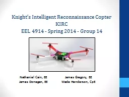
KIRC EEL 4915 Spring 2014 Group 14 Nathaniel Cain EE James Donegan EE James Gregory EE Wade Henderson CpE Project History and Motivation This is an unofficial NASA sponsored project ID: 193655
Download Presentation The PPT/PDF document "Knight’s Intelligent Reconnaissance Co..." is the property of its rightful owner. Permission is granted to download and print the materials on this web site for personal, non-commercial use only, and to display it on your personal computer provided you do not modify the materials and that you retain all copyright notices contained in the materials. By downloading content from our website, you accept the terms of this agreement.
Slide1
Knight’s Intelligent Reconnaissance Copter KIRCEEL 4915 - Spring 2014 - Group 14
Nathaniel Cain, EE James Donegan, EEJames Gregory, EEWade Henderson, CpESlide2
Project History and MotivationThis is an unofficial NASA sponsored projectTeam was provided a budget of $1,000Tasked to create two Unmanned Aerial Vehicles (UAV) working together to image an area autonomously
The objective is to test Delay Tolerant Networking (DTN) protocol useful in applications which tend to have long delays or disruptionsFuture applications include NASA missions such as the Pavilion Lake Research Project in Canada and other Earth science missionsSlide3
DTN Network
DTN “Delay Tolerant Network” will be used on the project, as it is one of NASA’s requirements
DTN is a networking protocol that resides as a virtual transport layer for computer communication networks, it is used to transmit and receive data over networks that are prone to delays and disruptions
DTN2, a version of DTN is an open source version of this software available online and runs on
linux
Both quadcopters as well as our ground station will have DTN2 installed as part of the KIRC softwareSlide4
GoalsDemonstrate the main features of DTN: data hopping over a mesh network, store and forward, and bundle handlingBuild a foundation for software that can be reconfigurable on a mission-by-mission basis as well as having the flexibility to integrate into other UAVs
Create flexible software, implement a Real Time Operating System (RTOS) on an ARM processor, and use digital control loops to provide compensation to motorsUse an image stitching software that can stitch together a composite image from multiple coordinate stamped imagesSlide5
Project ObjectivesLightweightDurableAdequate flight timeDynamically stable flightEase of manual flight control
Consistent, accurate, and stable autonomous flightSmall lightweight mounted imaging camera with reasonable clarity Ability to receive commands over a mesh networkSlide6
Autonomous Flight ObjectivesWe will program the quadcopters to take commands from a user at the ground station terminal to perform the following functions
without human intervention:Fly to a locationTake a snapshot at a locationImage an area (by a single quadcopter)Cooperatively image an area (by two quadcopters)Fail safe functionsReturn home (ability to easily set home location)HoverLand QuadcopterDirectly or indirectly relay information to the other quadcopter or the ground station (DTN software)Slide7
Project Specifications and Requirements
RequirementSpecification
Flight Time
>
10 minutes
Durability
Durable to
3
ft drop
Stability
≤ 5 mph winds
Camera
≥ 5 megapixels
Weight Limit
< 5 pounds
Altitude
> 100
ft
Time to Reach Min Altitude
< 30 secondsSlide8
Overall Project Block DiagramSlide9
Subsystem Block DiagramSlide10
Prototype Block DiagramSlide11
Final Block DiagramSlide12
Significant Design DecisionsWe chose a four rotor design over a single or six rotor design
Stability high altitudes (wind interference)Power consumptionLarge propeller force needed for fast cruising speedWe chose orientation II over orientation IFaster movement responseGreater StabilityMore challenging in terms of programmingSlide13
Significant Component Decisions: μCOur microcontroller had to meet some performance criteria
Must have a floating point unit to support control algorithm calculationsMust have multiple UART port for serial communication for with GPS and Raspberry PiMust have I2C ports for reading IMUMust have multiple PWM channels for motor control outputMust have an A/D converterMust support a Real Time Operating System (RTOS)At least a 32 bit processor with fast clock rate for control functions
Must have a Launchpad as well as surface mount IC available
Name
Vendor
Processor
RTOS Support
Availability
Price
UNO32
Digilent
PIC32MX320F128
No
Launchpad, Standalone
$26.95
Piccolo Launchpad
Texas Instruments
F28027F
Yes
Launchpad, Standalone
$17.00
Stellaris
Launchpad
Texas Instruments
EK-LMF120XL
Yes
Launchpad only
$13.49
Tiva
C Launchpad
Texas Instruments
TM4C123GH6PMI
Yes
Launchpad, Standalone
$12.99 Slide14
Significant Component Decisions: μCOur microcontroller had to meet some performance criteria
Must have a floating point unit to support control algorithm calculationsMust have multiple UART port for serial communication for with GPS and Raspberry PiMust have I2C ports for reading IMUMust have multiple PWM channels for motor control outputMust have an A/D converterMust support a Real Time Operating System (RTOS)At least a 32 bit processor with fast clock rate for control functions
Must have a Launchpad as well as surface mount IC available
Name
Vendor
Processor
RTOS Support
Availability
Price
UNO32
Digilent
PIC32MX320F128
No
Launchpad, Standalone
$26.95
Piccolo Launchpad
Texas Instruments
F28027F
Yes
Launchpad, Standalone
$17.00
Stellaris
Launchpad
Texas Instruments
EK-LMF120XL
Yes
Launchpad only
$13.49
Tiva
C Launchpad
Texas Instruments
TM4C123GH6PMI
Yes
Launchpad, Standalone
$12.99 Slide15
Tiva C Launchpad μCSlide16
Significant Component Decisions: IMUOur IMU must meet the following criteriaMust be less than $100 (preferably less than $50
)Must be I2C compatibleHave accelerometer, gyroscope, altimeter, and magnetometerMust work on 3.3V power and low currentMust fit on through-hole mounting shield of size less than the microcontrollerAll on board sensors must be available individually from at least one vendor so that they can be incorporated
into the PCB
design
We decided to choose
a 10
DoF
sensor stick because of size and satisfaction of our needsSlide17
10DoF IMUSlide18
Significant Component Decisions: GPSOur GPS must meet the following criteriaMust
have large enough signal strength to overcome motor EMISensitivity under -160dBm for tracking and navigationFast start up time; TTFF or time to first fix under 30sAt least 50-channel (possible number of satellites that can be used at one time)
Name
Vendor
Power
Number channels
TTFF
(seconds)
Sensitivity
(
dBm
)
Price
($)
GS407
S.P.K. Electronics Co.
3.3V@75mA
50
29
-160
$89.95
GP635T
ADH Technology Co.
5V@56mA
50
27
-161
$39.95
D2523T
ADH Technology Co.
3.3V@74mA
50
29
-160
$104.00Slide19
Significant Component Decisions: GPSOur GPS must meet the following criteriaMust
have large enough signal strength to overcome motor EMISensitivity under -160dBm for tracking and navigationFast start up time; TTFF or time to first fix under 30sAt least 50-channel (possible number of satellites that can be used at one time)
Name
Vendor
Power
Number channels
TTFF
(seconds)
Sensitivity
(
dBm
)
Price
($)
GS407
S.P.K. Electronics Co.
3.3V@75mA
50
29
-160
$89.95
GP635T
ADH Technology Co.
5V@56mA
50
27
-161
$39.95
D2523T
ADH Technology Co.
3.3V@74mA
50
29
-160
$104.00Slide20
Significant Component Decisions: Motor
Our Motors must meet the following criteriaMust have thrust capabilities to hover payload at less than 50% thrust capacityMust be powered by 15 V or lessMust be low priced, less than $20Must adhere to the above requirements and maintain a flight time greater than 12 minutes with a 5 Amp/hour batteryWe chose the NTM Prop Drive Series 28-30S 900kv motor because of cost, and calculated flight time using equations
and
where
= mass of the entire system, in grams
= max thrust for each motor, in grams
= lifespan of the battery in Ampere Hours
= current draw of motors and electrical circuits
Slide21
Why do we need an RTOS?Time sensitive applicationTasksMemory ManagementMultitaskingClock/Timers
PreemptionSlide22
Peripheral prioritiesSlide23
Ground Station User InterfaceSlide24
Control System
The quadcopters must be dynamically stabilized in flight in order to produce controllable flightAttitude control will be done digitally using classical PID (Proportional Integral Derivative) feedback controllers for each axis (shown below)The compensated output of the PID controller is sent to a PWM conversion matrix, and the respective PWM signals are sent to the ESCs and motorsInput to this control system will be from an RC controller (shown in next slide)Slide25
Control System (Cont’d)Input from the RC controller is done in multiple steps:Controller transmitter sends signal to receiver (2.4GHz)
Receiver converts signal to PWM for each channelPWM signals are sent to microcontrollerInterrupt driven program on microcontroller decodes PWM signals into duty cycle calculationsEach signal is translated into control input for attitude control systemSlide26
Navigation & Guidance System
The navigation control system, essentially the workhorse of the autonomous part of the project, will operate alongside the attitude control system
The navigation control system will use GPS, magnetometer, and altimeter sensors for position, heading, and altitude feedback
Most of this computing will be done on the Raspberry Pi, but the Tiva C will be reading the sensors and relaying the navigation information to the PiSlide27
Navigation & Guidance System (Cont’d)
The navigation control algorithms will be slightly different than the attitude control system
The quadcopter will essentially have a series of “way points” to fly to
Since civilian GPS has error to within a few meters, each way point will be described as a “bubble”, where within this bubble the quadcopter will be considered to be at the destination
The
autonomous control
of the quadcopter will be achieved using a state machine that describes to the flight computer exactly what actions to take and when to do themSlide28
Navigation State MachineSlide29
PCB Schematic: μCSlide30
PCB Schematic: IMU Slide31
PCB Schematic: Power CircuitSlide32
PCB LayoutManufactured by OSH ParkSlide33
Mounted Camera
Raspberry Pi Camera Module5 Megapixel imaging Slide34
Stitching SoftwareThe software will have locations of the positions of each pictures, and overlap neighboring pictures based on positionIn figure (a) below, w
e have an input of 4 pictures in red, blue, green, and yellow which are equally spacedIn figure (b) below, the output picture overlaps every input picture by 50% (a)
(b)Slide35
Stitching Software Example
(f)
(b)
(c)
(d)
(e)
(a)Slide36
Stitching Software Application
In our implementation, each photo taken by the quadcopter will have associated GPS coordinates, which will be used in the stitching software
(a)
(b)Slide37
Area Imaging Flight PathThe figure below shows one possible way a single quadcopter will image an areaSlide38
Team Organization/Work Distribution
NameRole
Nathaniel Cain
Team Lead,
NASA liaison,
Control Systems Lead
James Donegan
Power System Lead and PCB Backup
James
Gregory
Control Systems Backup, Schematic Design
and PCB
Wade Henderson
Software LeadSlide39
Project Budget and Financing
Category
Item
QTY
Price Ea. ($)
Total $
Status
Quad:ControlSys
…
Microcontroller Launchpad
2
$15.00
$30.00
Acquired
…
IMU Sensor Unit
2
$25.00
$50.00
Acquired
…
GPS Unit
2
$50.00
$100.00
Acquired
Quad:FlightSys
…
Speed Controller
8
$10.00
$80.00
Acquired
…
Motors
8
$20.00
$160.00
Acquired
…
Props
12
$4.00
$48.00
Acquired
…
Frame
2
$15.00
$30.00
Acquired
…
Li-Po Battery (4-5 A-h)
2
$40.00
$80.00
Acquired
…
RC Controller &
Reciever
1
$50.00
$50.00
Acquired
Quad:GuidSys
…
Embedded Linux Processor
2
N/A
Acquired
…
Power Cable
2
N/A
Acquired
…
SD Cards
2
N/A
Acquired
…
802.11G Wireless Card
2
N/A
Acquired
…
High Resolution Webcam
2
$50.00
$100.00
Acquired
Ground:GndStat
…
Laptop
1
N/A
Acquired
Quad:PCBHardW
…
Microcontroller Standalone
2
$10.00
$20.00
To be acquired
…
Accelerometer
2
$5.00
$10.00
To be acquired
…
Gyroscope
2
$5.00
$10.00
To be acquired
…
Magnetometer
2
$5.00
$10.00
To be acquired
…
Altimeter
2
$5.00
$10.00
To be acquired
TOTALS
All
$788.00
N/ASlide40
Project SuccessesSo far the group has completed the following tasks1.) Use RC controller to drive Motor through ESC2
.) Completed design of PCB3.) Pieced together the hardware of the first quadcopter (frame, mounted motors, mounted ESCs)4.) Successfully implemented image stitching software5.) Successful input and calibration of Real Time IMU data 6.) RTOS Implementation including I2C and UART7.) Significant progress on the control algorithmSlide41
Current Progress of the group
Overall Completion at 50%
Current Progress
% Completed
5
10
15
20
25
30
35
40
45
50
55
60
65
70
75
80
85
90
95
100
Research
Design
Prototype
Software
Testing
Overall Completion
Slide42
Project Difficulties1.) Dealing with acquiring parts during the Government Furlough in 2013 (NASA budget)2.) Dealing with lengthy shipping time for parts ordered from foreign
countries3.) Learning how to implement embedded software (drivers) into RTOS4.) Learning to use software interrupts, hardware interrupts, and tasksSlide43
Plan for Completion1.) Control Algorithm Tuning2.) Test first working prototype with manual control3
.) Add Raspberry Pi with guidance software4.) Test autonomous navigation5.) Test PCB6.) Final TestingSlide44
Questions or Suggestions?Thanks for listening!