/
OPW Engineered Systems has been manufacturing sight 31ow indicators fo OPW Engineered Systems has been manufacturing sight 31ow indicators fo

OPW Engineered Systems has been manufacturing sight 31ow indicators fo - PDF document

catherine
catherine . @catherine
Follow
345 views
Uploaded On 2021-08-19

OPW Engineered Systems has been manufacturing sight 31ow indicators fo - PPT Presentation

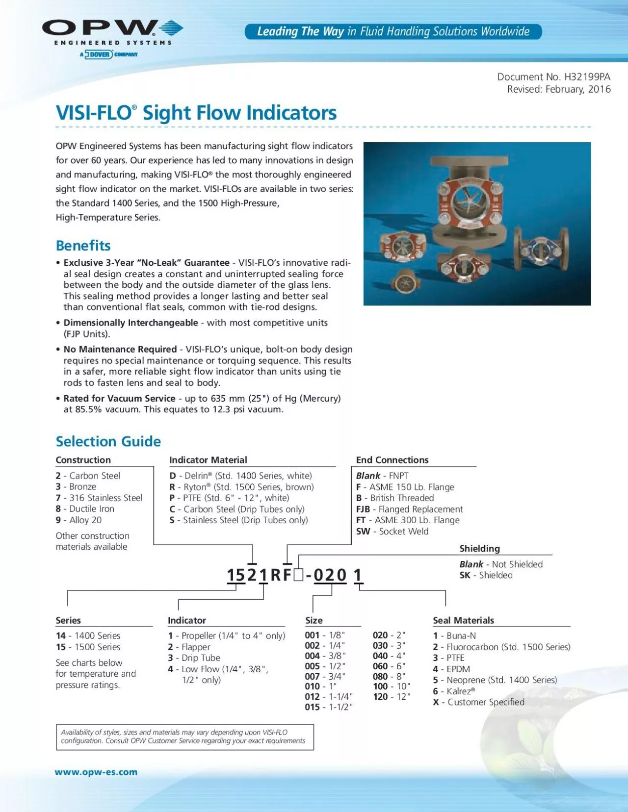
Series14 1400 Series 15 1500 SeriesSee charts below for temperature and Indicator1 Propeller 14 to 4 only 2 Flapper Drip Tube Low Flow 14 38 Construction2 Carbon Steel 3 Bronze ID: 867160

flow 149 step propeller 149 flow propeller step 1500 1400 series units visi drip opw maintenance glass sight unit

Share:

Link:

Embed:

Download Presentation from below link

Download Pdf The PPT/PDF document "OPW Engineered Systems has been manufact..." is the property of its rightful owner. Permission is granted to download and print the materials on this web site for personal, non-commercial use only, and to display it on your personal computer provided you do not modify the materials and that you retain all copyright notices contained in the materials. By downloading content from our website, you accept the terms of this agreement.


Presentation Transcript

1 OPW Engineered Systems has been manufact
OPW Engineered Systems has been manufacturing sight ow indicators for over 60 years. Our experience has led to many innovations in design the most thoroughly engineered sight ow indicator on the market. VISI-FLOs are available in two series: the Standard 1400 Series, and the 1500 High-Pressure, Series14 - 1400 Series 15 - 1500 SeriesSee charts below for temperature and Indicator1 - Propeller (1/4" to 4" only) 2 - Flapper - Drip Tube - Low Flow (1/4", 3/8", Construction2 - Carbon Steel 3 - Bronze - 316 Stainless Steel - Ductile Iron - Alloy 20Other construction materials available Indicator MaterialD - Delrin® (Std. 1400 Series, white) R - Ryton® (Std. 1500 Series, brown) P - PTFE (Std. 6" - 12", white) C - Carbon Steel (Drip Tubes only) - Stainless Steel (Drip Tubes only) End ConnectionsBlank - FNPT F - ASME 150 Lb. Flange - British Threaded - Flanged Replacement - ASME 300 Lb. Flange - Socket Weld ShieldingBlank - Not Shielded SK - Shielded - 3/8" - 1/2" - 3/4" - 1" - 10" Fluorocarbon (Std. 1500 Series) www.opw-es.com Document No. H32199PARevised: February, 2016 Leading The Way in Fluid Handling Solutions WorldwideAvailability of styles, sizes and materials may vary depending upon

2 VISI-FLO 2 , Alloy 20, , Others upon r
VISI-FLO 2 , Alloy 20, , Others upon request1400 Series (3" and Above)Tempered Soda LimeTempered BorosilicateSocket WeldPressure/Temperature Probe:Polycarbonate Lens CoverConsult Factory Construction and Material Service Rating - Continued Service Rating Flow Charts Seal and Indicator Operating TemperaturesVISI-FLO® Sight Flow Indicators - Technical Information Degrees FDegrees CHi-Temp PTFE / Kalrez With standard seals Stainless-steel units rated @ 195 PSIG Stainless-steel units rated @ 195 PSIG, Stainless-steel units rated @ 275 PSIG, ductile iron @ 245 PSIGNotes: Alternate seals may result in higher operating temperatures Temperatures up to 500º F possible with Hi-Temp PTFE seals 275 PSIG @ 100°F Max. PressureMax. Temperature 1400 Series Threaded/Flanged 1500 Series Threaded (1/4"-2") .7.813579204060801003005001000.9 10 90 108642.9 807060504030 PRESSURE DROP PSIPRESSURE DROP PSI FLOW GPM WATENOTE: Over 100 gpm Flapper indicator advised FLOW GPM WATE 209710865431224681030507090200400700 .7.81357920406080100300.924681030507090200400975.3.1.8.7.5.3.6.4.2.3.1 1/ 3/ 1/ 1/ 1 1-1/ 1/3/1/3/1-1/ 2 3 4 234 1-1/ 1-1/ VISI-FLO with Propeller Indicator .7.813579204060801003005001000.9109010 8642.9 807060

3 504030PRESSURE DROP PSI PRESSURE DROP PS
504030PRESSURE DROP PSI PRESSURE DROP PSI FLOW GPM WATENOTE: Over 100 gpm Flapper indicator advised FLOW GPM WATE 209710865431224681030507090200400700 .7.81357920406080100300.924681030507090200 400 97 5.3.1.8 .7 .5.3 .6 .4 .2 .3.1 1/3/1/1/11-1/ 1/ 3/ 1/ 3/ 1-1/ 234 2 3 4 1-1/ 1-1/ DIMENSIONAL DRAWINGS ARE AVAILABLE FROM THE DOWNLOAD SECTION OF OUR WEBSITE - Minimum Flow* Required to Turn Propeller 1435 (Low-Flow Orice Plate) Minimum Flow Requirement to Turn Propeller * VISI-FLO installed in horizontal position with deector opening down. IMPORTANT: OPW products should be used in compliance with applicable federal, state, provincial, and local laws and regulations. Productlimitations and compatibility with the environment and materials to be handled. OPW MAKES NO WARRANTY OF FITNESS FOR A PARTICULare based on the latest product information available at the time of publication. OPW reserves the right to make changes at anymodels without notice or obligation. 3 Shield Kits Shield Kit Installation Installation Instructions Maintenance Disassembly Instructions (Units up to 2") Seal Repair KitsVISI-FLO® Sight Flow Indicators - 1400 / 1500 Maintenance 1400SK - 1720Shield Kit, 1400 & 1500 Series All Shield K

4 its include Shield (1) = 1/4", 3/8", 1
its include Shield (1) = 1/4", 3/8", 1/2" Insert stud into open hole and turn to approximately Repeat steps 1, 2 and 3 in that order on second face Install shield on stud extension, resting shield on the nuts already Before installation, the user should check the unit for damage during shipping and freedom from defects such as lens scratches Check and remove any foreign material inside Determine direction of ow and install the unit according to the If unit is to be installed in a location or position where objects The VISI-FLO is not designed to be a load bearing component, therefore the piping should be supported accordingly. Propeller unit can be mounted in any plane or position Drip tube model must be mounted vertically with Flapper model should be mounted horizontally Periodic inspection (every 3 months for leakages is Before performing any maintenance on sight ow indicator, Do not attempt any maintenance or servicing without reading Fluorocarbon Neoprene 14 RK - 005 1Series 14 = 1400 Series 15 = 1500 SeriesRK Repair Kit Original seal material should be stamped on unit All kits include top & bottom seals, glass, gaskets & - 1/4", 3/8", 1/2" 2726 Henkle Drive • Lebanon, OH 45036 •

5 Phone (800) 547-9393 • (513) 461-0
Phone (800) 547-9393 • (513) 461-0113 • Fax (800) 245-8536 • (513) 932-9845 • www.opw-es.comVISI-FLO, #H32199PA Rev. 1 4 VISI-FLO® Sight Flow Indicators - 1400 / 1500 Maintenance NOTE: EPDM seals are NOT compatible with petroleum-based lubricants. A silicone-based lubricant must be used with EPDM.NOTE: EPDM seals are NOT Beveled Edge Assembly Instructions (Units up to 2")Step 1: • Install ow director, Single Plate VISI-FLO unitsStep 2: • Lightly lubricate seals with a light oil• Press seal into body, • (PTFE spacer ts inside seal)Step 3: • Drop glass on top of seal and • Be sure that beveled edge of Step 4: • Note: Propeller unit shown• Drop propeller or apper • Drip tube units skip this stepStep 5: • Note: Propeller unit shown• Orient second bridge so center boss • Press onto shaft until shoulder on Step 6: • Lightly lubricate O-ring with light 5 VISI-FLO® Sight Flow Indicators - 1400 / 1500 Maintenance Assembly Instructions (Units up to 2") ContinuedStep 7: Press glass inside O-ring making sure beveled edge of glass is facing towards retaining bridge.Step 8: • Place gasket, plate and nameplate over gl

6 ass• Make sure chamfer in the cente
ass• Make sure chamfer in the center of the plate faces Step 9: • Flow direction starts on the • Hand-tighten bolts with • Propeller units only: Make sure Step 10: • Drip Tube Versions Only: Drop bushing into body, either Assembly Complete! NOTE: Chamfer must be facing up Beveled Edge 6 Bolt Ears VISI-FLO® Sight Flow Indicators - 1400 / 1500 Maintenance Detailed Disassembly (3" & Above) Assembly Instructions (Units 3" & up)NOTE: EPDM seals are NOT compatible with petroleum-based lubricants. A silicone-based lubricant must be used with EPDM.Step 1: • Remove bolts, washers, nameplate, plate, and gasketStep 1: • Make sure that apper or propeller (whichever Step 2: • Fit apper or propeller assembly Step 3: • Secure with lock washers and boltsStep 2: • Remove glass and O-ring• Repeat process for other side• Thoroughly clean all sealing surfaces with a non-abrasive cleaning padStep 4: • Press drip tube into end opposite bolt hole ears• 3"and 4" SST have Teon NOTE: 3" and 4" carbon-Step 5: • Propeller version shown• For apper or propeller • Lightly lubricate O-ring • If building drip tube 7 VISI-FLOÂ

7 ® Sight Flow Indicators - 1400 / 1500 Ma
® Sight Flow Indicators - 1400 / 1500 Maintenance Assembly Instructions (Units 3" & up) ContinuedStep 6: • Wedge beveled glass down inside O-ring, with the smallest • Once glass begins to resist further seating, stopStep 7: • Place one gasket and plate over glass• Make sure chamfered side Step 8: • With your palm, press down with Step 9: • Place nameplate on top correct way• Flow direction for propeller version can be determined • Flow starts on the side with bolt ears, and travels through to the opposite side• Drip tube version is opposite this• Flapper units do not have a ow directionStep 10: • Secure components with bolts and at washers• Hand-tighten with wrench only• Repeat on opposite side. Do not attempt any maintenance service while the equipment is in operation. System pressure must be relieved and the product drained before attempting any service on the unit. The line must be locked out while service is in progress. Proper thermal relief must be provided at all times while OPW products do not eliminate possible exposure to hazardous substances. The conditions of handling and use are beyond our control, and we make no guar

8 antee and assume no liability for damage
antee and assume no liability for damages or injuries related to the use of our products. Follow the safety precautions outlined in the Material Safety Data Sheets for the material being used. It is the responsibility of the user to comply with all federal, state and local regulations. Always employ proper safety precautions and handling Proper seal and wetted material part selection is critical for safe operation. To assure maximum life for the service intended, use only those materials compatible with the uids being handled. Please note material being supplied and make certain that it is OPW VISI-FLOs are NOT recommended for compressed gas Failure to follow these warnings could result in serious personal Assembly Complete! 8 1¼", 1½" WasherCap, Plated SteelGasket*Propeller-DelrinPropeller-RytonPropeller-PTFEFlapper-DelrinFlapper-RytonFlapper-PTFESpacer, PTFE*Drip Tube WashersCap, Plated SteelGasket*Button, PTFEPropeller-DelrinPropeller-RytonPropeller-PTFEFlapper-DelrinFlapper-RytonFlapper-PTFELockwasher, SSTDrip TubeIndicator Support Arm 2726 Henkle Drive Lebanon, OH 45036, USA Phone: +1 (800) 547-9393 Fax: +1 (800) 245-8536www.opw-es.com Distributed By: *Included in 1400RK/1500RK Seal Kit